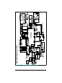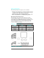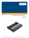
1
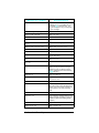
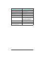
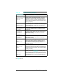
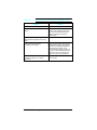
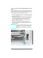
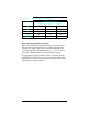
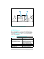
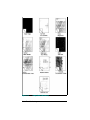
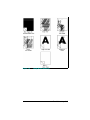
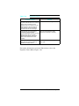
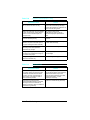
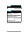
7
LaserJet 5 Error Map
The LaserJet 5/5M/5N printer has error messages that are
similar to the LaserJet 4/4M/4+/4M+. Use the following table to
look up the LJ5 error and take the recommended action. If the
recommendation is to see another error, for example See 00
POWERSAVE, look up the recommendation for that error in the
Printer Message Troubleshooting section (Tables 7-1 and 7-2).
Note
The LaserJet 5 printer’s Go key replaces both the
Online and Continue keys previously used to
resolve some of the temporary errors in the
LaserJet 4 and 4 Plus printers.
Note
For any LaserJet 5 error message preceded with a
number from 20 through 81, look up the
equivalently-numbered message in Table 7-1 and
proceed as directed.
Message on LJ 5/5M/5N
Recommendations
CLEARING MEMORY
See 07 RESET
CLOSE PRINTER COVER
See 12 PRINTER OPEN
CONTINUOUS TEST, PRESS JOB CANCEL
KEY
See 04 SELF TEST
DATA RECEIVED
The received data is waiting for a form
feed. (Takes the place of the Form Feed
indicator on the LJ4.)
ENGINE TEST
See 15 ENGINE TEST
FACTORY DEFAULTS BEING RESTORED
See 09 MENU RESET
INCOMPATIBLE ENVELOPE FEEDER
INSTALLED
Indicates that an envelope feeder has
been installed that is not compatible with
the LJ5. Press GO to clear the error. The
feeder will not appear in any control
panel or PJL messages.
LaserJet 5 Error Map 7-A
Message on LJ 5/5M/5N
Recommendations
INCOMPATIBLE TRAY 3 INSTALLED
Indicates that a lower cassette has been
installed that is not compatible with the
LJ5. Press GO to clear the error. The
tray will not appear in any control panel
or PJL messages.
INITIALIZING (powerup only)
See 05 SELF TEST
INSTALL TONER CARTRIDGE
See 14 EP CART
INSTALL TRAY 2
See PC INSTALL
INSUFFICIENT MEMORY, JOB CLEARED
See W3 JOB ABORTED
INSUFFICIENT MEMORY, PRINTING AT
300 DPI
See W4/7 JOB 300/[page protect size]
MANUALLY FEED [envelope size]
See ME FEED [envelope size]
MANUALLY FEED [paper size]
See MF FEED [paper size]
MEMORY LOW, PAGE SIMPLIFIED
See W1 IMAGE ADAPT
MEMORY SETTINGS CHANGED
See WM MEM CNFIG N/A or
WM CHK MEM CNFIG
OFFLINE
See 00 OFFLINE
[personality] MEMORY FULL, STORED
DATA LOST
See
PLEASE WAIT
This message is displayed whenever the
device is in the process of flushing the
pipeline so it can go offline or into the
menus. (Takes the place of the flashing
Online indicator.)
POWERSAVE ON
See 00 POWERSAVE
PRINTING CONFIGURATION PAGE
See 05 SELF TEST /
06 PRINTING TEST
PRINTING DEMO PAGE
See 06 DEMO PAGE
PRINTING FLASH PAGE
This message is displayed while a flash
file system page is being formatted and
printed. Upon successful completion, the
device returns to an online and ready
state.
PRINTING FONT LIST
See 06 TYPEFACE LIST
PROCESSING JOB
This message is displayed whenever the
device is actively processing a user’s job.
(Takes the place of the flashing Ready
indicator.)
READY
See 00 READY
REMOVE DUPLEX JAM
See 13 DUPLEX JAM
7-B LaserJet 5 Error Map
WM [Personality] MEM FULL
Message on LJ 5/5M/5N
Recommendations
REMOVE PAPER JAM
See 13 PAPER JAM
REQUESTED LANGUAGE NOT AVAILABLE
See W2 INVALID PERS
RESETTING ACTIVE I/O
See 07 RESET
RESETTING ALL I/O
See 07 RESET
RESTORING FACTORY SETTINGS
See 08 COLD RESET
TONER LOW
See 16 TONER LOW
TRAY 2/3 EMPTY
Indicates Tray 2 or 3 has run out of paper
and has not been selected as the current
job’s paper source. If the problem
persists, check for a binding sensor flag
or replace the appropriate sensor.
TRAY x LOAD [paper or envelope size] See xx LOAD [paper or envelope size]
WARMING UP
See 02 WARMING UP
x LOAD [envelope size]
x=Tray 1 or Envelope Feeder
See xx LOAD [paper or envelope
size]
LaserJet 5 Error Map 7-C
7-D LaserJet 5 Error Map
7
Troubleshooting
Pre-Troubleshooting Procedures
Preliminary Operating Checks
Prior to troubleshooting a specific printer problem, you should
ensure that:
• The printer is being maintained on a regular basis as
described in Chapter 4.
• The customer is using acceptable media as specified in the
User’s Manual.
• The printer is installed on a solid, level surface.
• The line voltage does not vary more than 10% from the
nominal rated value as specified on the Power Rating Label.
• The operating environment for the printer and paper is within
•
•
•
the temperature and humidity specifications listed in Chapter
1 of this manual.
The printer is never exposed to ammonia fumes such as those
produced by diazo copiers, or office cleaning materials.
The printer is not exposed to direct sunlight.
Non-HP components (such as refilled toner cartridges, font
cartridges, and memory boards) are removed from the printer.
Troubleshooting 7-1
Printer Message Troubleshooting
Printer Message Summary Table
Table 7-1 is a list of all status, attendance, error, and service
messages affecting the printers. The table also identifies the
action required to correct the situation identified by the message.
When the action requires removal and replacement of an
assembly or PCA, refer to the applicable section of Chapter 6 for
instructions. For general location of components, refer to
Troubleshooting Aids at the end of this chapter.
Table 7-1
Printer Messages
Message
Symptoms and Recommendations
Blank Display
Refer to the “Blank Display” Table 7-3.
00 READY
Proceed; printer is ready to use.
00 POWERSAVE
POWERSAVE ON
Printer is in Power Save Mode. Press any key to take
printer out of Power Save mode. Receipt of data or an error
condition will also take printer out of Power Save mode. The
job will print when the fuser is warmed up (may take up to
45 seconds).
00 OFFLINE
Printer is off line and not able to receive data. Press On
Line*.
02 WARMING UP
Wait until printer signals ready.
05 SELF TEST
The non-printing portion of Self Test is in progress. Wait for
the printer to display the 00 READY message.
06 PRINTING TEST
PRINTING
CONFIGURATION PAGE
Self Test printing. Wait for the printer to display the 00
READY message.
06 TYPE PRINTOUT
Printing sample characters from available typefaces. Wait
for the printer to display the 00 READY message. (Note: the
format is different for PCL and PostScript.)
06 TYPEFACE LIST
PRINTING FONT LIST
Printing a Typeface List. (Note that PCL/Postscript formats
are different.)
06 DEMO PAGE
PRINTING DEMO PAGE
Printing a Demonstration Page. (Note that PCL/Postscript
formats are different.)
06 CONFIG PAGE
Printing a Configuration Page. Appears only with PostScript
installed in the printer.
*Press Go on the LJ5.
7-2 Troubleshooting
Table 7-1
Printer Messages (continued)
Message
Symptoms and Recommendations
07 RESET
RESETTING [xxx]
Returns all printer settings to Printing Menu settings, and
clears buffered pages, temporary soft fonts, and macros.
Wait for the printer to display the 00 READY message. See
the Reset Menu section in Chapter 3 for more details.
08 NVRAM_INIT
Printer is initializing non-volatile RAM. This allows other
personalities to access non-volatile RAM.
08 COLD RESET
Returns both Configuration and Printing Menu selections to
the factory settings. Ensure that the Configuration Menu
settings are correct before placing the printer on-line. Wait
for the printer to display the 00 READY message. See the
Reset Menu section in Chapter 3 for more details.
RESTORING FACTORY
SETTINGS
RESET=MENU
09 MENU RESET
09 RESET ACTIVE I/O
09 RESET ALL I/O
FACTORY DEFAULTS
BEING RESTORED
Follows a Control Panel [Reset] selection. The printer
returns all Printing, PCL, PS, and Job Menu items to the
factory settings. Clears buffered page data, temporary soft
fonts, and temporary macros. See Chapter 3 for more
details.
10 RESET TO SAVE
The Printing, PCL, PS, and Config Menus were changed
while data, temporary fonts, or temporary macros were
present in printer memory, or while the printer was in the
middle of a job. Press [Continue]* or [On Line]*. Your
changes remain recorded in the menu but do not become
active until the printer is reset, or the job boundary is
detected.
12 PRINTER OPEN
CLOSE PRINTER COVER
Close the Top Cover Assembly. If the problem continues,
refer to the “12 PRINTER OPEN Message” section.
13 PAPER JAM
REMOVE PAPER JAM
Open printer and clear any paper within the printer. Press
[Continue]* or [On Line]* to reprint the page. If the problem
persists, refer to “13 PAPER JAM Message” section.
13 DUPLEX JAM
REMOVE DUPLEX JAM
Check for any paper in the Duplexer area. If problem
persists, refer to the Duplex Section (Appendix A).
14 NO EP CART
Ensure that the Toner Cartridge is installed correctly (fully
seated into the printer). Try a new Toner Cartridge. If the
problem continues, refer to the “14 NO EP CART Message”
section.
INSTALL TONER
CARTRIDGE
15 ENGINE TEST
This message is displayed during the execution of a print
engine self-test. When this test is complete, the printer
returns to the ready state, but remains off line.
16 TONER LOW
The toner cartridge is almost empty. Replace the Toner
Cartridge. Although you can continue to print for a short
while, make sure that the print quality does not degrade
past the acceptable level. If the problem continues, refer to
“16 TONER LOW” Message" section.
*Press Go on the LJ5.
Troubleshooting 7-3
Table 7-1
Printer Messages (continued)
Message
Symptoms and Recommendations
18 AUX IO INIT
This message is displayed when the MIO (AUX IO) card is
in the process of initializing. During initialization the MIO is
not active, but since the printer supports I/O switching, the
printer remains on line and this becomes a status message.
Display clears automatically (this may take up to a minute,
depending upon the card).
18 AUX IO NT RDY
The MIO (AUX IO) card is not ready. See the user’s manual
for the MIO card. The serial and Bi-Tronics parallel ports
continue to operate normally. To clear the display, you must
remove the card, and power-cycle the printer. The
[Continue]* key does not clear the display.
18 MIO INIT
The MIO card is initializing. This is a status message.
During initialization the MIO is not active, but since the
printer supports I/O switching, the printer remains on line.
Displays clears automatically (may take up to a minute,
depending on the card).
18 MIO NOT READY
The MIO card is not ready or not connected to a working
network. The serial and Bi-Tronics parallel ports will
continue to operate normally. To clear the display, switch the
printer OFF, remove the card and switch printer ON.
[Continue]* will not clear the display. See MIO
documentation for troubleshooting.
20 MEM OVERFLOW
Indicates a memory overflow. Too much data is being sent
to the printer and the printer has run out of memory.
Pressing the [Continue]* key causes the printer to print only
the information it received. If the error persists, it may be
necessary to simplify the print job (such as fewer fonts and
less graphics information), or have the customer purchase
additional memory.
20 INSUFFICIENT
MEMORY
21 PRINT OVERRUN
21 PAGE TOO COMPLEX
Indicates that the information being sent to the printer is too
complex for the printer (the formatting capabilities of the
printer cannot keep up with the formatting instructions
being sent to it by the computer).
If the error persists, it may be necessary to simplify the job
(reduce the number of characters, number of fonts used,
number of pixels addressed, cursor repositions, or reduce
addressing the same pixel location multiple times). This
problem can also be resolved by adding at least one
additional memory PCA, and setting PAGEPROTECT=[LTR,
LGL, or A4], if applicable.
*Press Go on the LJ5.
7-4 Troubleshooting
Table 7-1
Printer Messages (continued)
Message
22 ERROR
22 SERIAL I/O ERROR
22 PARALLEL I/O
ERROR
22 HP MIO ERROR
40 ERROR
40 BAD SERIAL DATA
FORMAT
40 HP MIO ERROR
Symptoms and Recommendations
For serial/Bi-Tronics parallel configuration, the computer
and printer are not communicating because of improper
signal protocols. This is an I/O buffer overrun error.
Parallel configuration: may mean a loose cable connection.
Serial configuration: wrong pacing option may be selected.
(If you are using an RS232 serial connection, the HP
LaserJet printer uses XON/XOFF and DTR signal protocols
rather than ENC/ACK protocol.) Press [Continue]* to clear
the error message (data is lost).
The printer encountered an error while transferring data
from the computer. For serial I/O configuration, the error
may have occurred because you turned ON or OFF your
computer while the printer was on line, or your printer’s
baud rate or parity was not the same as the computer’s. For
network MIO cards, this means there was an abnormal
connection break. Make sure the printer is set at the same
baud rate as the computer. Press [Continue]* to clear the
error message. For network MIO cards, see the user’s
manual for your card.
41.[X] ERROR
41.x PRINTER ERROR
x=1, 2, 4 ,5
A temporary error occurred while printing. Press the
[Continue]* key to clear the error. If the error persists, refer
to “41.X ERROR Message.”
41.3 ERROR
41.3 UNEXPECTED
PAPER SIZE
The paper size selection knob or MP paper size does not
match the installed paper or more than one sheet of paper
was picked up.
50 SERVICE
50 FUSER ERROR
Power OFF the printer for a minimum of 10 minutes. If the
problem continues, refer to the “50 SERVICE error” section.
51 ERROR
Indicates loss of laser beam for over 2 seconds. Press
[Continue]* to clear this error. If the error persists, refer to
the “51 ERROR Message” section.
51 PRINTER ERROR
52 ERROR
52 PRINTER ERROR
Indicates scanner motor is unable to maintain the proper
speed. Press [Continue* to clear this error. If the error
persists, refer to the “52 ERROR Scanner Malfunction”
section.
*Press Go on the LJ5.
Troubleshooting 7-5
Table 7-1
Printer Messages (continued)
Message
53.XY.ZZ ERROR
Symptoms and Recommendations
An error occurred during configuration and validation of
SIMM memory:
X Hardware Type:
0:ROM
1:RAM
2:Flash
Y Hardware Device:
0: Internal Memory
1: SIMM Slot 1
2: SIMM Slot 2
3: SIMM Slot 3
4: SIMM Slot 4
ZZ Error Number:
0: Unsupported Memory
1: Unrecognized Memory
2: Unsupported Memory Size
3: Failed RAM Test
4: Exceeded Maximum RAM Size
5: Exceeded Maximum ROM Size
6: Invalid SIMM Speed
7: SIMM Reporting Information Incorrectly
8: SIMM RAM Parity Error
LaserJet 4/4m only
9: SIMM ROM Needs To Be Mapped To An Unsupported
Address
10:SIMM Address Conflict
11:PDC XROM out of bounds
12:Could not make a temporary mapping
Replace the SIMM device that caused the error. Pressing
[Continue]* allows you to continue but the SIMM device that
caused the error is not configured. If the SIMM device has
more than one bank of memory, the good banks are
configured.
*Press Go on the LJ5.
Note
Refer to the “Product Family Compatibility
Matrix” in Chapter 1, or for the LaserJet 5,
Appendix B to verify correct memory for the
printer.
7-6 Troubleshooting
Table 7-1
Message
55 ERROR
55 PRINTER ERROR
Printer Messages (continued)
Symptoms and Recommendations
Indicates a communications problem between the DC
Controller PCA and the Formatter PCA. Pressing
[Continue]* clears the error and resumes printing.
Perform the Test Print operation to verify DC Controller
functionality. If the message persists, check for any cable
damage, and check the DC voltages, or replace the DC
Controller.
57 SERVICE
57 MOTOR FAILURE
57.1 SERVICE
This message indicates that a main motor failure occurred.
Power cycle the printer. If the error persists, first check the
connections at the main motor and DC Controller, then
replace the main motor to clear the error. See “57 (or
57.1) SERVICE message.
58 SERVICE
This errors indicates the DC Controller detects an exhaust
58 FAN MOTOR FAILURE fan failure in either the printer or the optional duplexer. See
57.2 SERVICE
the “58 (or 57.2) SERVICE” section for more information.
61.[x] SERVICE
X=0 - 4
Printer encountered a parity error when accessing the RAM
memory SIMM in slot “X”. If X=0, the faulty SIMM slot was
not detected. Turn OFF the printer, then back ON. (Data
stored in printer is lost.) If the error is still present, Turn OFF
the printer and verify that the indicated SIMM is correctly
installed. Turn ON the printer . If the error is still present,
turn OFF the printer, and remove the SIMM board. Turn ON
the printer. If the error message does not appear, the
problem is on the SIMM board; if the error still appears, the
problem is in the printer’s internal memory.
62.[x] SERVICE
x=0 - 5
Printer identified a problem while checking its memory. “X”
refers to the device the printer was checking when it
encountered the error.
0: Internal Memory
1-4: SIMM Slot
5: Cartridge
If the printer contains a SIMM memory board, turn OFF the
printer. (Data stored in printer is lost.) Verify that the SIMM
is installed correctly, and turn ON the printer. If the error is
still present, turn OFF the printer, and remove the SIMM
board. Turn ON the printer. If the error message does not
appear, the problem is on the SIMM board.
63 SERVICE
63 NEEDS SERVICE
The printer found a problem in its internal RAM memory.
Switch OFF the printer, and then switch ON. (You lose any
data stored in the printer.) If the problem persists, replace
the Formatter PCA.
*Press Go on the LJ5.
Troubleshooting 7-7
Table 7-1
Printer Messages (continued)
Message
64
64
65
67
SERVICE
PRINTER ERROR
SERVICE
SERVICE
Symptoms and Recommendations
The printer identified an internal service error. If this error
appears, turn the printer OFF, and then back ON. If the
problem persists, replace the Formatter PCA.
68 ERROR
68 NVRAM ERROR
The printer detected an error in the nonvolatile memory
(NVRAM). Press [Continue]*, then check your Control Panel
settings. If the problem persists, replace the Formatter PCA.
68 SERVICE
68 NVRAM FULL
The printer’s nonvolatile memory is full because new
feature sets were installed. Power the printer OFF, then
back ON. If the problem persists reinitialize the NVRAM by
pressing the [Item]** key while powering on the printer.
Reset the page count, cold reset paper size, display
language, and all other applicable control panel settings.
70 SERVICE
HP LJ 4+/4M+ Only
A firmware SIMM problem was identified. Remove or
replace the firmware SIMM.
71 SERVICE
HP LJ 4+/4M+ Only
A firmware SIMM problem was identified. Remove or
replace the firmware SIMM.
79 SERVICE [xxxx]
An internal controller error has occurred. Power the printer
OFF, then back ON. If this error persists, replace the
Formatter PCA. Remove third party memory, if installed.
May also be caused by driver or application
incompatibilities, or defective toner cartridge.
80 SERVICE [xxxx]
The formatter PCA has been informed of an irrecoverable
error by the MIO card. Power cycle the printer. If the error
persists, replace the MIO card.
81 SERVICE [xxx]
Formatter manufacturing error. Cold Reset the printer. If
the problem persists, replace the Formatter PCA.
EE LOAD [envelope
size]
The printer received a request for an envelope size that is
not loaded currently in the optional envelope feeder, or the
feeder is empty. Envelope size may be: COM10, MONARCH,
or DL, C5, B5, or ENVELOPE. Load the correct envelope
size into the tray, or press [Continue]* to use the size of
media installed in the feeder.
ENVELOPE FEEDER
[envelope size]
FE CARTRIDGE
An accessory cartridge was removed or replaced while the
printer was on line. (This message appears even if the
cartridge was not used.) Power cycle the printer to clear
this message. Ensure that the printer is off line when the
cartridge is removed or installed. If a font cartridge is not
recognized, verify that it is installed correctly.
FI INSERT CART
An accessory cartridge was removed while the printer was
in an error state. To clear this message, insert the cartridge,
clear any error conditions, then remove the cartridge.
*Press Go on the LJ5. **Press Job Cancel on the LJ5.
7-8 Troubleshooting
Table 7-1
Printer Messages (continued)
Message
Symptoms and Recommendations
FR REMOVE CART
An accessory cartridge was installed while the printer was
in an error state. To clear this message, remove the
cartridge, clear the pending error condition, then install the
cartridge.
ME FEED
[envelope size]
MANUALLY FEED
[envelope size]
This message is displayed when there is a request for a
manually fed envelope. envelope size may be: COM10,
MONARCH, DL, C5, B5, or ENVELOPE. Insert the appropriate
envelope size into the MP tray (Tray 1), and press [On Line]*
to print.
MF FEED
[paper size]
This message is displayed when there is a request for
manually fed media. Paper size may be: LETTER, LEGAL,
EXEC, or A4. Insert the appropriate media size into the MP
tray, and press [On Line]* to print, or press [Continue]* to
feed from the Paper Cassette (Tray 2).
MANUALLY FEED
[paper size]
PC INSTALL
INSTALL TRAY 2
xx LOAD [paper size
or envelope size]
TRAY x LOAD [size]
ENVELOPE FEEDER
[envelope size]
The printer currently has the Lower Cassette or duplexer
selected as the paper source, and has detected that the
Paper Cassette (Tray 2), which serves as a paper guide for
the Lower Cassette, is not installed. Install (reseat) the
Paper Cassette.
The printer received a request for a paper or envelope size
not available in the printer. The xx is MP (Multi-Purpose), PC
(Paper Cassette), or LC (Lower cassette). Paper size may
be: LETTER, LEGAL, EXEC, or A4; for MP tray, envelope
sizes may be COM10, MONARCH, DL, C5, or B5. Load the
correct paper tray and/or media, or press [Continue]* to use
the media in the installed tray(s). The printer continues
automatically. If the problem persists, refer to page 7-13.
*Press Go on the LJ5.
Troubleshooting 7-9
Clearable Warnings
A clearable warning indicates a transient condition in the
printer. The printer continues on line while the message is
displayed in place of 00 READY. A clearable warning appears each
time the printer alters resolution or page protection (this causes
reconfiguration of memory), or aborts a job due to an invalid or
uninstalled personality, or insufficient memory. Clear the
message by pressing [Shift] + [Continue] (or Go for the LaserJet 5).
7-10 Troubleshooting
Table 7-2
Clearable Warning Messages
Message Displayed
W1 IMAGE ADAPT
MEMORY LOW, PAGE
SIMPLIFIED
Meaning
The printer received a graphics print file that was too
complex to print at the requested resolution. The printer
automatically processed the file in the highest resolution
possible with the memory installed. Add additional memory
to print the file at full resolution. Check the printout for loss
of data or print quality.
REQUESTED LANGUAGE
NOT AVAILABLE
The job was not printed because the requested personality,
such as PostScript, was not installed. Install the language in
which the files are sent, together with enough memory to
support that language.
W3 JOB ABORTED
INSUFFICIENT MEMORY
JOB CLEARED
The printer was forced to abort the print job because there
was not enough installed memory to support the printer
language used.
W4
W5
W6
W7
300/OFF
300/LTR
300/A4
300/LGL
The job was printed at 300 dpi with page protection set as
specified in the message. To print the job as requested,
install additional memory.
W8 JOB 600/OFF
W9 JOB 600/LTR
W0 JOB 600/A4
The job was printed at 600 dpi with page protection set as
specified in the message. To print the job as requested,
install additional memory.
WM MEM CNFIG N/A
The printer did not have enough memory when switched on
to support the previous settings for I/O buffering and /or
Resource Saving, probably because you removed a
memory SIMM, added a new personality SIMM, or added
the optional duplex unit.
W2 INVALID PERS
JOB
JOB
JOB
JOB
MEMORY SETTINGS
CHANGED
WM CHK MEM CNFIG
MEMORY SETTINGS
CHANGED
WM [personality]
MEM FULL
[personality]
MEMORY FULL
I/O Buffering and /or Resource Saving settings were altered
when the printer was switched on because the printer did
not have enough memory. This usually occurs after memory
has been removed from the printer. (You can check settings
by printing a self test.)
The Resource Saving memory area for the specified
personality is full. Press [CONTINUE]* to continue printing
(some data will be lost). The current job will print, but some
resources (downloaded fonts, etc.) may not be saved. If this
error occurs frequently, you may need to adjust Resource
Saving settings.
*Press Go on the LJ5.
Troubleshooting 7-11
Printer Message Troubleshooting
Procedures
When the following procedures require removing and replacing
an assembly or PCA, refer to the applicable section in Chapter 6
for instructions.
Blank Display
Table 7-3
Blank Display
Checks
Is the power on?
Action
1. Check the ON/OFF switch and verify the power is
plugged in.
2. Press a Control Panel key to verify problem still
exists.
Is the fan working?
1. If the fan is working, check the cabling to the
Control Panel. If the cabling is good, replace the
Formatter first, then the Control Panel.
2. If the fan is NOT working, measure the DC
voltage levels (refer to Table 7-39). If the voltage
levels are good from the power supply to the DC
Controller and the fan is not working, replace the
DC Controller. If the voltage levels are not present
at TB1, replace the DC Power Supply.
7-12 Troubleshooting
MP/PC/LC (Tray 1/2/3) LOAD Message
The conditions that result in MP/PC/LC LOAD or (TRAY 1/2/3)
messages are:
• The absence of any input tray.
• The absence of media in either tray.
• The tray size switches may be defective and not recognize
•
the presence of the paper tray. The tray is sensed as the
tray-identifier tabs contact one or more of the three tray
identifier microswitches.
The Universal Tray paper size dial setting does not match
the installed paper.
The MP/PC/LC LOAD message is also generated when the user or
software requests a paper size other than that installed.
The Paper Sensing Arms are located in the paper input areas of
the printer. During normal operation, the Paper Sensing Arm
flags rest on the media installed in the paper tray. The Sensing
Arm flags are attached to shafts. The opposite end of the shaft is
a photointerrupter that rotates through the sensors on the Paper
Control PCA. These sensors are:
• PS4 Paper out-MP tray.
• PS2 Paper out-PC tray.
• PS6 Paper out-Lower Cassette.
• PS7 Paper out-Envelope Feeder.
The presence of paper in the paper tray is sensed by the paper
sensor arm. When paper is in the cassette, the sensor arm rests
on top of the paper in the tray. At this point, the sensors are not
blocked. When the tray is empty, the arm swings through its
travel. The photointerrupter attached to the paper sensor arm
shaft rotates and blocks the sensor diode.
Troubleshooting 7-13
Table 7-4
“MP/PC/LC (Tray 1/2/3) LOAD” Message Checks
Checks
Action
Is media present in the tray(s).
Install media.
Are the proper trays fully inserted in the
printer?
Reseat the cassettes. Make sure each
cassette is fully seated into the printer.
Ensure that the Universal Paper tray
selector knob setting matches the
installed paper.
Does the Control Panel’s or application’s
Paper size setting match the tray being
used?
Correct the setting to match tray.
Is the expected tray size being
recognized by the printer?
Ensure that the image is sized correctly
(formatted) for the paper size selected.
Proceed to the following cassette size
switches functional check. Check
switches 603/4/5 if feeding from the PC
tray (Tray 1). Check switches 851/2/3 if
feeding from the Lower Cassette. see
Figures 7-14 and 7-15 for locations.)
Are any of the tray identifier tabs broken
on either PC (Tray 1) or LC (Tray 2)
paper tray?
Inspect the tray for damage. If damaged,
replace the tray.
7-14 Troubleshooting
Cassette Size Switches (SW603, SW604, SW605) Functional
Check
Before beginning this test, remove the Lower Cassette Base and
the Envelope Feeder. Also, PS2 (PC or Tray 2 Paper Out sensor)
must be engaged for this test to be performed reliably. Push PS2
up towards the rear of the printer with your hand.
1 Power ON the printer with the PC tray removed. Wait for the
PC LOAD XXX message. Set PAPER=LETTER in the Printing Menu
using the Control Panel.
2 With PS2 engaged, press and hold the lower and upper paper
size switches (refer to Table 7-5). The display should read 00
READY. If the display does not change, the switches are
defective. Inspect the switch activating mechanism and/or
replace the Paper Control PCA.
3 Repeat the test, this time setting the paper size to legal
(PAPER=LEGAL) and pressing the top two switches. If the
printer responds with 00 READY, all three switches have been
tested and verified.
Note
The LaserJet 5 printer will require you to set the
paper size, followed by a self test to generate the
equivalent TRAY 2 LOAD message. Use the Job
Cancel key between tests to cancel the Self Test
printout.
Figure 7-1
PC Tray Size Sensing Microswitches Location
Troubleshooting 7-15
Table 7-5
Switch Logic for Cassette Size
Cassette
Cassette Size Sensing Switch
SW603/851
SW604/852
SW605/853
Upper
Middle
Lower
Legal
ON
ON
OFF
Letter
ON
OFF
ON
A4
OFF
OFF
ON
Executive
OFF
ON
ON
No Cassette
OFF
OFF
OFF
Paper Size Sensing Lower Cassette
The operator must set the appropriate paper size for the Lower
Cassette using a dial which, in turn, activates switches on the
cassette base. This setting is sent to the DC Controller on the
serial data bus (SLI). The printer posts a 41.3 SERVICE error if
the media is different from that selected with the switch.
To verify proper operation of the LC (Tray 3) switches, lock out
the MP (Tray 1) and PC (Tray 2) trays (in the Config Menu) and
perform the same test with Lower Cassette switches as was done
for the PC tray (Tray 2) switches.
7-16 Troubleshooting
PC Empty Sensor (PS2) Functional Check
1 Power on the printer with the PC tray (Tray 2) empty.
2 After the 05 SELF TEST and the 02 WARMING UP cycles, the PC
LOAD LETTER (or A4) or TRAY 2 EMPTY message appears.
3 Add paper to the PC tray and re-install the tray.
4 The display should read 02 WARMING UP, then 00 READY. If
the PC LOAD or TRAY 2 EMPTY message persists, replace PS2.
PS4 Check (MP Tray Empty Sensor)
1 With the printer powered ON and 00 READY displayed, select
the Config Menu from the Control Panel.
2 Configure the MP Tray (Tray 1) as a cassette (MP TRAY=CASS
or TRAY 1=CASSETTE).
3 Lock out the remaining paper trays (LOCK= PC LC or LOCK
TRAY= 2 3).
4 Remove any paper from the MP Tray (Tray 1). The printer
should display an MP LOAD [paper size] message. For the
LaserJet 5 printer, run a Self Test to generate the TRAY 1
LOAD message.
5 Insert paper into the MP Tray (Tray 1). If the MP LOAD (TRAY
1 LOAD) message persists (or if the load message never
occurred), PS4 or the sensor flag is defective.
Troubleshooting 7-17
12 Printer Open Message
The 12 PRINTER OPEN (or CLOSE PRINTER COVER) display tells the
operator to close the printer’s top cover. The DC Controller
detects the Printer Open condition through the position of
SW601, which is located on the Paper Feed Assembly PCA . A tab
underneath the top cover Door engages SW601 through a slot in
the Top Cover Assembly.
In addition to signaling that the top cover is open, SW601 enables
the +24B VDC which controls the high voltage for the printing
processes, and the AC Voltage for the Fuser Assembly.
Table 7-6
12 PRINTER OPEN Checks
Checks
Action
Is the Top Cover Assembly open?
Ensure the Top Cover Assembly is firmly
closed, and that the protrusion that
engages the switch actuator is not
broken.
With the top cover open, check that the
switch actuator does engage the switch.
Use a slim object to manually engage
SW601. Listen for a definite “click” as the
switch is engaged (see Figures 7-2 and
7-14).
Has the Paper Control PCA on the Paper SW601 has an actuator that can be
Feed Assembly been replaced?
deleted during reassembly. Ensure that
this actuator is installed correctly.
Is the DC Controller PCA defective?
7-18 Troubleshooting
Measure the 24 VDC on J201, pins 8 and
9 on the DC Controller (see Figures 7-16
and 7-17 for locations). If this 24 volts
toggles as SW601 is activated, replace
the DC Controller. If it does not, replace
the Paper Control PCA or the cable. Also
check J201-6 (DOPEN). This voltage
should be 5 VDC when the printer is
open, and 0 when the printer is closed. If
not, replace the DC Controller PCA.
SW601 Functional Check
1 Open the Top Cover Assembly.
2 The message 12 PRINTER OPEN (or CLOSE PRINTER COVER)
should appear.
3 Close the top cover. The 02 WARMING UP message should
appear.
4 If the messages do not occur, check the switch actuator (see
Figure 7-2, callout 1) on the top cover, and check that the
plunger that covers the switch is in place (see also Figure 7-14
for switch locations).
5 Replace the Paper Control PCA.
Figure 7-2
Location of the Top Cover Closed (SW601)
Actuator
Troubleshooting 7-19
13 PAPER JAM Message
Paper jams occur when paper fails to arrive at or clear the paper
path sensors in the allotted time. Paper movement is monitored
primarily by two paper sensors. These are described below and
illustrated in Figure 7-3).
1 PS1, the Input/Registration Sensor, located in the Paper Feed
Assembly.
2 PS3, Exit Sensor, monitors paper in the Fuser Assembly.
Figure 7-3
PS1 and PS3 (Paper Path Sensors) & PS5 Paper
End Sensor
When troubleshooting paper jams, the door associated with the
sensor must be opened and closed to clear the jam message. For
instance, if PS3 (Exit Sensor) detected the paper jam, and the jam
was cleared through a method other than opening the rear door,
the message remains in the display until the rear door is opened
and closed. Likewise, the top cover must be opened before a jam
detected by PS1 is cleared.
The DC Controller monitors these sensors, and detects both the
leading and trailing edge of the paper to verify that the paper
clears the sensors in the allotted time. If the paper does not
arrive at, or clear the sensors in the allotted time, the DC
Controller senses a paper jam. The paper jam information is
transferred to the Formatter PCA, which displays the 13 PAPER
JAM message.
Note also that if PS5 (MP Tray or Tray 1) Paper End Sensor on
the Sensor PCA is bad (Figure 7-3, item 3), a paper jam will be
reported when paper is fed from the MP Tray (or Tray 1).
7-20 Troubleshooting
Table 7-7
Jam Location
Input Area Jams
(Sensed by PS1.)
Paper Jam Troubleshooting Checklist
Checks and Action Required
1. Check that the Transfer Roller is fully seated and shows no
sign of wear.
2. Check that the Toner Cartridge is fully seated.
3. Check that the cassettes are not overfull and the media is
loaded correctly.
4. Ensure that the media meets specs. (media is not too
smooth or rough), and it has been stored properly.
5. Ensure that the paper tray is fully seated (especially if
printing from the Lower Cassette).
6. Ensure that the spring force of the Lower Cassette is set
correctly.
Registration Area
Jams
(Sensed by PS1.)
1. If paper is damaged at the Registration Sensor (PS1),
check that the Transfer Charge Roller is properly seated.
Lower Cassette
Paper Jams
(Sensed by PS1.)
1. The LC Tray (Tray 3) is not fully seated into the printer. Seat
the LC Tray firmly into the printer.
Fuser Assembly
Jams
(Sensed by PS3.)
1. Check that the Fuser Pressure Roller Levers are down
(LJ4 and 4 Plus Only).
False Paper Jams
1. PS1, PS3, or PS5 are damaged or mechanically broken.
2. The Lower Cassette feed pressure (spring force)
adjustment is incorrect. Set the spring force as shown in
Chapter 3.
2. Check that the Exit Sensor Arm (PS3) is free throughout its
travel and that the Exit Sensor Arm is installed correctly.
2. The sensor wires are damaged or disconnected.
3. The rear door is open.
Paper Jam occurs
when the last
sheet of paper is
fed from the tray.
4. Paper out sensors in the paper tray or envelope feeder
may be defective, or the sensor flags may be broken or
missing. PS2 is the sensor for the PC Tray (Tray 2), PS4 is
the sensor for the MP Tray (Tray 1), PS6 is the sensor for
the LC Tray (Tray 3), and PS7 is the sensor for the
Envelope Feeder.
Troubleshooting 7-21
PS1 (Input/Registration Sensor) Check
1 Power ON the printer with the top cover open. Wait for the
12 PRINTER OPEN (or CLOSE PRINTER COVER) message.
2 Engage PS1 by taping it down.
a For the LaserJet 5, install the toner cartridge.
3 Close the top cover. The 02 WARMING UP message should
display.
4 After the fuser warms up, the main motor should turn on.
5 The 13 PAPER JAM message appears if the sensor is working
correctly.
6 If the 13 PAPER JAM message does not appear, check that PS1
was fully engaged, then replace PS1.
7 Remove the tape from PS1, install the Toner Cartridge and
close the top cover.
8 The display should change from 02 WARMING UP to 00 READY.
If the 13 PAPER JAM message persists, replace PS1.
Figure 7-4
PS1 Input/Registration Sensor
7-22 Troubleshooting
PS3 (Exit Sensor) Check
1 Open the rear door (cover) of the printer.
2 The display should read 13 PAPER JAM (or REMOVE PAPER JAM)
immediately after the door is opened.
3 Close the rear cover. The display should change from
02 WARMING UP to 00 READY.
a If the 00 READY message does not appear, check that the
rear door is not damaged, and the the door closes and
latches properly.
b If the PAPER JAM message does not appear, replace PS3.
Pickup Motor Functional Test (M2)
There is not a good method with which to access the test points
around the Pickup Motor (M2) circuit. Therefore, when
troubleshooting Pickup Motor failures, perform the following in
the order listed (see Figures 7-11 and 7-12 for component
location).
1 Reseat J601 and J602 on the Paper Control PCA.
2 Reseat J201 on the DC Controller. Reseat J703 on the Sensor
PCA.
3 Verify that the Paper Control PCA and the Sensor PCA are
firmly seated into one another.
4 Replace the Pickup Motor.
5 Replace the Paper Control PCA.
6 Replace the Sensor PCA.
Troubleshooting 7-23
Lower Cassette Functional Check
When troubleshooting a Lower Cassette failure, always prove the
failure by removing the Lower Cassette from the printer. Next,
test the printer’s ability to move and print media satisfactorily
without the Lower Cassette installed.
The Lower Cassette is a field-serviceable item. The procedures for
removing and replacing the Lower Cassette components are in
Chapter 6. Replacement parts for the Lower Cassette Assembly
are listed in Chapter 8.
After the failure has been associated with the Lower Cassette
Assembly, perform the following in the order given. Test the
repair after each replacement.
1
2
3
4
Reseat all connectors in Lower Cassette.
Replace the Lower Cassette Pickup Motor.
Replace the Paper Control PCA.
Replace the DC Controller.
7-24 Troubleshooting
14 NO EP CART Message
The printer detects the presence of the Toner Cartridge and the
level of toner present in the cartridge through the condition of the
ANTIN signal. The ANTIN signal becomes part of the serial data
stream used to communicate with the DC Controller (see Figure
7-5 for cartridge components). Troubleshoot the 14 NO EP CART
(or INSTALL TONER CARTRIDGE) message as follows:
1 Reseat the Toner Cartridge. Try a new or known good Toner
Cartridge.
2 Check the High Voltage Contacts for damage. If the contacts
are dirty or damaged, clean the contacts after the repair.
3 Replace the High Voltage Power Supply.
4 Check and reseat the HVPS cable.
5 Replace the DC Controller.
16 Toner Low Message
The TONER LOW message results as the level of toner in the
cartridge cavity falls past the minimum level. The level is sensed
by a mechanism similar to an antenna, which detects the AC
Developer Bias Voltage applied to the developer mixture. If the
TONER LOW message cannot be cleared by shaking or replacing the
Toner Cartridge, perform the steps listed for troubleshooting the
14 NO EP CART message.
Troubleshooting 7-25
6
1
5
4
2
3
Figure 7-5
Toner Cartridge Components
Table 7-8
Toner Cartridge Components
Callout
Assembly
1
Toner Low Voltage Contact
2
Developer Roller High Voltage Contact
3
Developer Roller
4
Photoconductive Drum
5
Charge Roller High Voltage Contact
6
Charge Roller
7-26 Troubleshooting
41.X ERROR Message
A 41.X ERROR (misprint) indicates that a temporary malfunction
has occurred with the print engine (NOT a Formatter error).
Occasional occurrences of this message can be expected. However,
persistent 41 ERROR messages indicate a problem requiring
attention.
The 41.X ERROR is usually accompanied by a blank, or partially
printed page. Pressing the [Continue] (or Go) key re-prints the
page, and continues the print job.
A 41 ERROR occurs due to the following conditions:
• Incorrect Universal Tray Switch setting. Set the Universal
•
•
•
Tray and the Lower Cassette Tray paper size as shown in
Chapter 3.
Wrong size paper in tray. Check that the Universal Tray,
and/or the Lower Cassette settings match the installed paper.
An unstable or temporary loss of the Beam Detect pulse. This
problem normally is accompanied by a partially printed page,
often with thin horizontal black lines, deformed characters, or
solid black areas. Loss of the Beam Detect pulse for more than
2 seconds results in a 51 ERROR condition.
Paper reaching the Input Paper Sensor (PS1) before it is
expected. This is accompanied by a blank page. This normally
is due to paper feed problems.
Proceed as directed in the following table.
Troubleshooting 7-27
Table 7-9
41.X ERROR Checks
Error Message
Recommended Action
Reseat all connectors on the DC Controller, the Laser
41.1 ERROR
Noisy Vertical Sync (VS) Drive PCA, the Scanner Connector and the Beam Detect
Connector.
41.2 ERROR
Beam Detect (BD)
weak or unstable.
Reseat all connectors on the DC Controller. Also check the
Laser Scanning Assembly connections.
41.3 ERROR
Paper Multifeed
1. Incorrect size selection on the cassette.
2. One of the cassettes is overfull. Remove the extra
paper from the overfull cassette.
3. Check the paper for edge damage. Improperly cut
edges can lock together causing multi-feeds.
4. Check that the pickup rollers and separation pad are
not worn. Replace the rollers and pad as a set if
necessary. Ensure that the corners of the paper are
tucked in the tray’s retainers.
5. Check the paper tension adjustment on the optional
Lower Cassette, if attached. Refer to procedure in
Chapter 3.
41.4 ERROR
Vertical Sync Late (VS)
Signal
Reseat the DC Controller and Formatter PCA Connections.
41.5 ERROR
Undetermined Cause
Reseat the DC Controller and Formatter PCA connections.
See Figures 7-11 through 7-17 for connector locations.
7-28 Troubleshooting
50 SERVICE Error - Fuser Malfunction
Warning
The Fuser Assembly is HOT. Allow the assembly
time to cool before servicing.
The purpose of the fusing system is to maintain a constant
temperature on the fuser roller. A high intensity fusing lamp,
located inside the fuser roller, provides the high temperature
required for the fusing process. While the printer is in standby
mode, a temperature of approximately 172° C is maintained on
the fuser roller. While the printer is in printing mode, a
temperature of around 183° C is maintained.
The main components of the Fuser Assembly are the fusing lamp
and its associated fusing and pressure rollers, a thermistor,
thermoprotector, and the AC controller/safety circuitry in the AC
Power Supply. The fusing lamp is a specially designed 460 watt
(220V), or 500 watt (115V) halogen lamp that operates at line
voltage. The thermistor is a resistor whose value changes with
temperature. At room temperature the resistance value of the
thermistor should be between 180k ohms and 280k ohms.The
thermoprotector is a switch designed for over-temperature
protection, and opens when the temperature reaches 230° C. The
thermoprotector will not reset when the fuser cools. It may be
necessary to replace the thermoprotector or fuser assembly if the
thermoprotector opens.
The following conditions result in a fusing error:
1 Unable to maintain a temperature above approximately
180° C.
2 A temperature above 230° C.
3 A condition wherein a temperature of 165° C is NOT reached
within 90 seconds after power-up.
Note
If a 50 SERVICE error message is displayed, turn
the printer OFF for at least 10 minutes. Failure
to wait the full 10 minutes before turning the
printer ON results in a continuation of the error
message and the shutting off of the fuser lamp
current during this time, though the source of the
error may have already been resolved.
Troubleshooting 7-29
Table 7-10
50 SERVICE Fuser Malfunction Checks
Checks
Action
Is the Fuser Assembly correctly
seated?
Reseat the Fuser Assembly. Allow
adequate time for the error message to
clear (10 minutes) and turn the printer
ON.
Is the Fuser Bulb/ Thermoswitch open?
The fuser bulb and thermoswitch are
wired in series. To check if one or the
other is defective, perform the following:
1. Remove the Fuser Assembly from the
printer.
2. Use an ohmmeter and measure the
continuity between pins (see Figure
7-6, callout 1). It should read about 2
ohms (about 4 ohms for the 220 volt
fuser). If an open condition is detected,
either the fusing bulb or the
thermoswitch is defective. Replace the
defective component (refer to Chapter
6) or replace the complete Fuser
Assembly.
Is the Thermistor defective?
1. Remove the Fuser Assembly and let it
cool to room temperature.
2. Use an ohmmeter and measure the
resistance between pins (see Figure
7-6, callout 2) It should read about 220
K ohms +/- 40 K ohms at ambient
room temperature. If the thermistor is
either open or shorted, replace the
thermistor (refer to Chapter 6) or the
complete Fuser Assembly.
Does the error persist?
1. Verify all cabling is correct.
2. Replace the following components in
the order given:
Power Supply Assembly
DC Controller PCA
See Figure 7-11 for Fuser Assembly location and Chapter 6 for
removal and replacement, as necessary.
Note
The 50 SERVICE error message can be cleared
immediately by shorting the C202 leads on the
HP LaserJet 4/4M (or the C205 leads on the HP
LaserJet 4 Plus/4M Plus/5/5M/5N) on the DC
Controller. Remove the Formatter PCA to access
the DC Controller as shown in Chapter 6.
7-30 Troubleshooting
Figure 7-6
Fuser Assembly Connector
51 ERROR Message
The 51 ERROR, and the 41.2 ERROR are caused by Beam Detect
failures. If the beam detect signal is lost for more than 2 seconds
the error is posted as a 51 ERROR. The 41.2 ERROR can be cleared
by pressing [Continue] (or Go). The 51 ERROR may be cleared by
power cycling the printer.
Table 7-11
51 ERROR Beam Detect Checks
Checks
Action
1. Are all connectors on the DC
Controller properly seated?
Inspect connectors and wiring. Reseat or
replace cables if necessary.
2. Is the Laser/Scanner Assembly
Defective?
A defective Laser/Scanner Assembly can
cause a 51 ERROR by spinning the
scanning mirror at the wrong speed.
Replace the Laser/Scanner Assembly.
3. Is the DC Controller Defective?
Replace the DC Controller.
4. Has the printer been moved from a
cold to a warm room?
Allow the printer to stand 6 hours until
any condensation has dissipated.
Troubleshooting 7-31
52 ERROR Scanner Malfunction
The scanner motor is a flat, brushless, DC motor. Motor operation
is completely controlled by the DC Controller.
The scanner motor is enabled when the printer is powered-up
(during the printer’s power-on self test), or whenever the PRINT
command is received by the Formatter PCA. The scanner motor
makes a distinctive sound when starting. The sound can be
described as a “variable pitch whirring” sound. Listen for the
sound of the scanner motor when troubleshooting the 52 ERROR.
Laser/Scanner Assembly Functional Checks
Initiate a Self Test. As the test begins, listen for the sound of the
scanner motor. If the motor cannot be heard, perform the
following in the order given:
1 Check the Laser/Scanner and the Power Supply cables.
Replace if necessary.
2 Replace the Laser/Scanner Assembly.
3 Replace the DC Controller.
7-32 Troubleshooting
57 (or 57.1) SERVICE Message (Main Motor
Failure)
The 57 SERVICE indicates that the DC Controller PCA detected a
general motor failure. The Main Motor drives all moving
components in the printing process. The Main Motor is a 4-phase,
DC servo motor controlled by the DC Controller PCA.
The formatter detects a Main Motor failure when:
• The Main Motor does not come up to speed within one second
of receiving drive voltage.
• The Main Motor deviates from the correct speed for one second
after reaching the correct speed.
Main Motor Functional Checks
• Inspect the gear train for debris that would block the free
operation of the gears.
• Check the gears in the Toner Cartridge for wear and binding.
• Reseat J211 (or J214 on the HP LaserJet 4 Plus/4M Plus) on
•
the DC Controller PCA, and the main connector on the Main
Motor Assembly. Refer to Figures 7-16 and 7-17 for the DC
Controller PCA connector locations.
If the problem persists, check that the +24B Voltage is present
on the DC Controller. If the voltage is not present, replace the
DC Controller. If the voltage is present, and the motor does
not rotate, replace the Main Motor Assembly (see Figure 7-11
for location).
Troubleshooting 7-33
58 (or 57.2) SERVICE (Fan Failure)
The 58 SERVICE indicates that the DC Controller detected a
failure in the Exhaust Fan (FM1) in the printer or the optional
duplexer. When troubleshooting this problem, perform the
following steps in the order given.
1 Check that the fan is mounted correctly in its shroud.
2 Check that the fan blades are not blocked.
3 Check that the Cooling Fan connector is firmly seated on the
DC Controller (see Figure 7-16 or Figure 7-17 for location).
If the above checks are satisfactory, replace the fan.
Note
Verify the direction of air flow. Air should blow
out of the printer.
7-34 Troubleshooting
Image Defect Summary
The quality of the printer’s output is subject to the judgment of
the user. This section of the manual helps you define print
quality defects, and understand what factors affect print quality.
The print samples shown in the following figures illustrate some
print quality defects. Keep copies of print quality defects
encountered in the field with an explanation of their causes for
future reference.
The image defects listed below are covered in the following tables.
(For major assembly, connector, and switch locations, see Figures
7-11 through 7-18 later in this chapter.)
• Black Pages.
• Any Faint Print Condition
• Faulty Registration
• Vertical White Streaks.
• Right-hand Image Missing.
• Small Print Voids
• Random Horizontal Black Lines
• Repetitive Defects.
• Smeared Print/Improper Fusing.
• Distorted Print.
• Black Pages with Horizontal White Strips.
• Image Skew.
• Improperly Sized Image.
• Vertical Dark Streaks.
• Large Print Voids.
• Background Scatter.
• White or Blank Pages.
Troubleshooting 7-35
Figure 7-7
Image Defect Summary
7-36 Troubleshooting
Figure 7-8
Image Defect Summary
Troubleshooting 7-37
Table 7-12
Black Pages
Possible Cause
Action
The HVPS connections are dirty.
Clean the HVPS terminals (see Figure
7-18 for layout).
The HVPS is installed improperly. If the
HVPS has been removed and replaced,
it may not be seated properly.
Remove the HVPS, and check the
connectors for damage. Reseat the
HVPS, being certain to fully seat the
connectors.
Bad Primary Charging Roller.
Replace the Toner Cartridge.
The HVPS is defective.
Replace the HVPS.
DC Controller PCA. The laser drive
circuitry is damaged so that the laser is
always on.
Replace the DC Controller PCA, followed
by the Formatter PCA if required.
Table 7-13
Any Faint Print Condition
Possible Cause
Action
Printer set to Economode.
Change driver and/or Control Panel
settings to ECONOMODE=OFF.
Toner Cartridge.
Replace the Toner Cartridge.
Print density set improperly. The higher
the print density setting, the more toner
transferred to the drum.
Set the print density to a darker level.
Replace the high voltage power supply if
this has no effect.
The paper finish, conductivity, or
Try a known good source of paper from a
moisture content may not be suitable for freshly opened package. Refer to the HP
the electro-photographic printing process. LaserJet Family Paper Specifications
Guide for media specifications.
The transfer roller may be defective.
Replace or reseat the roller.
Weak or no developer bias. If
inadequate, or no developer bias is
produced, toner is not attracted to the
image written on the drum.
Adjust the print density setting as shown
in Chapter 3.
7-38 Troubleshooting
Table 7-14
Faulty Registration
Possible Cause
Action
Paper. The surface of the paper may be
too smooth for the pickup roller to move
the paper through the paper path.
Change paper. Try a brand of paper
known to be good.
Worn Pickup Roller and Separation Pad.
If the Paper Pickup Roller, or the
Separation Pad are sufficiently worn, the
leading edge of the paper may not reach
the registration assembly in time.
Replace the Pickup Roller and
Separation Pad together.
PS1 faulty. If the Input/Registration
sensor (PS1) is broken, it can not sense
the presence of paper at the registration
point.
Replace the Input/Registration Sensor.
Drive Gears. If any gear within the gear
drive train becomes excessively worn or
dirty, erratic paper movement results,
causing image misregistration.
Examine the gears along the paper path
for wear and contamination. Clean and
inspect the gears. Replace any broken or
defective gears.
Paper Tray. The paper tray may be
preventing the paper from moving
through the printer.
Verify that the tray is loaded correctly.
Verify that the paper tray is seated fully
into the printer. If possible, exchange tray
with another printer to see if the problem
is associated with the tray. Note the HP
LaserJet 4/4M tray is NOT
interchangeable with the HP LaserJet 4
Plus/4M Plus tray. The LJ5 paper trays
are not compatible with the LJ4 or LJ4+.
Replace the paper tray.
DC Controller replaced.
If the DC Controller was replaced, adjust
VR202 as shown in Chapter 6.
Paper Input Assembly replaced.
The HP LaserJet 4/4M Paper Input
Assembly is NOT compatible with the HP
LaserJet 4 Plus/4M Plus. The LJ5 Paper
Input Assembly is not compatible with the
LJ4 or LJ4+ Input Assemblies. Installing
a non-compatible Input Assembly results
in paper input registration problems.
Troubleshooting 7-39
Table 7-15
Right-Hand Image Missing
Possible Cause
Action
No toner available for print.
Shake/replace the EP Toner Cartridge.
Laser shutter may be blocking the beam
Ensure that the mechanism that lifts the
shutter is functional, for example, the
shutter doesn’t stick in its travel, and is
lifted evenly.
Table 7-16
Small Print Voids
Possible Cause
Small voids on black, or near-black
printed images may be caused by
imbedded toner on the
electro-photographic drum. Cartridges
that are run for long periods of time in
high temperature and humidity conditions
may develop this problem.
Table 7-17
Action
Replace the EP Toner Cartridge. If the
printer is installed in a hot or humid
location, tell the customer to move the
printer to a better location.
Random Horizontal Black Lines
Possible Cause
Action
Laser/Scanning Assembly misaligned or
damaged.
Replace the Laser/Scanner Assembly.
DC Controller PCA
Replace the DC Controller PCA.
Table 7-18
Vertical White Streaks
Possible Cause
1.No toner is available for print, or the
toner level is low.
Action
Shake the EP Toner Cartridge, replace
the cartridge if the problem persists.
2.The lenses within the Laser/Scanning
Replace the Laser/Scanning Assembly.
Assembly may be contaminated, blocking
(or diffusing) the laser light.
7-40 Troubleshooting
Table 7-19
Repetitive Defects
Possible Cause
Action
Toner Cartridge. The circumference of
the photoconductive drum is 3.75 inches
(94mm). The circumference of the
developer roller is 2 inches (51mm). If a
defect appears in the print image at
these intervals, assume the defect is
associated with the Toner Cartridge.
Replace the Toner Cartridge.
Fuser Assembly. The Fuser Roller’s
circumference is approximately
2.5 inches (63mm) for the LJ4, and 3-1/8
(79mm) for the LJ4+/5. If a defect
appears at this interval, assume the
defect is associated with the Fuser
Assembly.
Clean the Fuser Assembly rollers.
Replace the assembly if necessary.
Dirty Roller. Any dirty roller along the
paper path may result in a pattern of
repetitive print image defects.
Examine and clean rollers along the
paper path.
For further information on interval dimensions, refer to the
Repetitive Defect Ruler, Figure 7-19.
Troubleshooting 7-41
Table 7-20
Smeared Print/Improper Fusing
Possible Cause
Action
Fuser levers not in place.
(All LJ4, some LJ4+, N/A on LJ5)
The Fuser Assembly has shipping levers
that must be lowered during the setup
process. See Chapter 3 for instruction on
how to lower the fusing levers.
Media. The media may not be acceptable
for laser printing. Heavy paper stock is a
common cause of smeared print and
improper fusing.
Verify that the media meets
specifications as shown in the HP
LaserJet Family Paper Specifications
Guide.
Dirty Fuser Assembly. The print smears if Replace the Fuser Assembly and clean
the Fuser Assembly is dirty.
the printer.
Bent Static Teeth. If the static teeth are
defective, the print could smear prior to
the paper entering the Fuser Assembly.
If the teeth are bent or defective, replace
the Static Teeth Assembly.
Worn Gears. If the drum and paper are
not moving at the same speed the
characters may smudge.
Replace the Toner Cartridge.
Foreign object in paper path. Something
is smearing the unfused toner image on
the surface of the paper.
Remove any foreign material. Try a new
Toner Cartridge.
Orange Packing Spacers not removed.
Some HP LaserJet 4 only.
Remove Orange Packing Spacers.
Table 7-21
Distorted Print
Possible Cause
Paper Path. If the paper does not move
at a uniform speed, the print image will
be affected. Characters that are either
too tall or too short (in the direction of
paper motion), are usually a result of
drive mechanism problem.
Action
Examine the paper transport rollers
along the paper path for wear. Replace if
excessive wear exists. Inspect and
replace the Toner Cartridge, Drive Gear
Assembly, Main Motor, or Fuser
Assembly as necessary.
Laser/Scanning Assembly. Wavy,
Replace the Laser/Scanning Assembly.
irregular-shaped characters, or irregular
line margins in the scan direction of
printing are usually a result of a defective
Laser/Scanning Assembly.
7-42 Troubleshooting
Table 7-22
Black Pages with Horizontal White Strips
Possible Cause
Laser/Scanning Assembly or DC
Controller PCA.
Table 7-23
Action
Replace the Laser/Scanning Assembly
followed by the DC Controller PCA, if
necessary (see Figure 7-12 for locations).
Image Skew
Possible Cause
Action
Input/Registration Sensor (PS1). The
Replace the Input/Registration Sensor.
Paper Pickup Roller positions the leading Skew tolerance for the printer is 1.5mm
edge of the paper at the
over 260mm page length.
Input/Registration Sensor (PS1). If this
sensor is defective it may not sense the
presence of the paper reliably (on time).
Drive Gears. If any gear within the gear
drive train becomes excessively worn, or
is excessively dirty, erratic paper
movement would result, leading to image
misregistration.
Closely examine the gears along the
paper path for wear and contamination.
Clean and inspect the gears. Replace
any defective gear.
Paper Tray. The paper tray may be
preventing the paper from freely moving
through the printer.
Verify that the tray is loaded correctly.
Verify that the paper tray is seated fully
into the printer. Switch trays to verify that
the problem follows the tray. Replace the
paper tray.
Paper. The surface of the paper may be
too smooth for the pickup roller to move
the paper through the paper path.
Change paper. Try paper known to be
good.
Paper too heavy?
See Paper Specifications in Chapter 2.
Troubleshooting 7-43
Table 7-24
Improperly Sized Image
Possible Cause
Action
PC tray Microswitches. The paper tray
microswitches indicate the paper size of
the installed tray. This information is used
to format the print image to the size of
the paper installed in the tray. If the paper
tray microswitches are defective, the
image is formatted incorrectly.
Perform the “Cassette Size Switches
(SW603, SW604, SW605) Functional
Check” on page 7-15. Ensure that the
correct envelope size is selected if
appropriate.
PS 5 is defective. PS 5 senses the
trailing edge of the media being fed from
the MP tray.
If improperly sized images result from
printing from the MP tray, check that PS
5 is functioning correctly mechanically
and electrically. This feature allows
odd-sized media to be printed with the
MP tray. Troubleshoot PS 5 as shown in
the following procedure.
MP Paper Size is not set correctly.
Use the MP Paper Size Button on the
Front Panel to correctly configure paper
size for the MP Tray.
PS5 Check (MP Tray Paper End Sensor) Functional Test
1 Make a test sheet by cutting a notch in the trailing edge of a
sheet of paper as shown in Figure 7-9.
2 Perform the set up procedures listed for the PS4 check (MP
Tray Empty Sensor) on page 7-17, and put the test sheet into
the MP tray when the display reads XX LOAD LEGAL.
3 The self test print should stop 2 to 5 mm above the notch (see
Figure 7-9).
4 Print that extends into cut out area indicates that the sensor
PS5 is not free in its travel or is defective. Ensure that the
sensor lever is free throughout its entire range of travel. If
not, replace the lever or the sensor itself.
7-44 Troubleshooting
Figure 7-9
PS5 Test Sheet
Troubleshooting 7-45
Table 7-25
Vertical Dark Streaks
Possible Cause
Action
Dirty Primary Charge roller.
Change the Toner Cartridge.
Bad Toner Cartridge.
Replace the Toner Cartridge.
Incompatible media. During media
manufacture, inks, or other finishing
processes may interfere with the
electro-photographic or fusing process.
Change type of media.
Table 7-26
Large Print Voids
Possible Cause
Action
Defective laser shutter.
Check the laser shutter for free operation
when inserting the EP Toner Cartridge.
EP Cartridge Support damaged,
improperly positioned, or missing.
Refer to item 4 in Figure 8-4a. Guide
must be installed properly above the EP
Cartridge, between the laser shutter
opening and the fuser stop plate.
Bad transparencies. Transparencies
exhibit this problem if they are not
designed for proper toner adhesion.
Use Hewlett-Packard-approved
transparencies (refer to the HP LaserJet
Family Paper Specifications Guide).
Bad paper lot. The surface of the paper
may be too smooth for proper toner
adhesion.
Try a known good paper from a reliable
source (refer to the HP LaserJet Family
Paper Specifications Guide).
Poor fusing. Toner may not be fused
properly to the media.
Try a known good paper from a reliable
source (refer to the HP LaserJet Family
Paper Specifications Guide).
Print image fusing may not occur
correctly.
Replace Fuser Assembly (see Figure
7-11 for location).
Wet paper. The paper may be damp.
Try a new batch of paper. Store the paper
in a dry area.
Transfer roller is dirty.
Replace the transfer roller.
7-46 Troubleshooting
Table 7-27
Background Scatter
Possible Cause
Action
Defective Toner Cartridge. The Toner
Cartridge may be internally damaged.
Replace the Toner Cartridge.
Bad paper lot. The paper moisture
content, conductivity, or surface finish
may be incompatible with the
electro-photographic process.
Try a different paper lot (see the HP
LaserJet Family Paper Specifications
Guide) for paper specifications.
Print density set incorrectly. If the print
density is set incorrectly, background
scatter can result, particularly with
envelopes.
Adjust the print density.
Inside of printer dirty. If toner dust leaked
out of the EP Toner Cartridge, this
problem can occur.
Clean the inside of the printer.
Troubleshooting 7-47
Table 7-28
White or Blank Pages
Possible Cause
Action
Defective laser shutter.
Check the laser shutter for free operation
when inserting the EP Toner Cartridge.
EP Cartridge Support damaged,
improperly positioned, or missing.
Refer to item 4 in Figure 8-4a. Guide
must be installed properly above the EP
Cartridge, between the laser shutter
opening and the fuser stop plate.
Toner Cartridge. No toner is available for
print.
Remove sealing tape or replace the
Toner Cartridge.
No Transfer Roller voltage. Without
transfer charge roller voltage, toner
cannot be attracted from the surface of
the drum to the paper.
Perform the “Half Self Test Functional
Check” which follows to check all other
electro-photographic processes.
No Developing Bias. With no Developing
Bias charge, toner is not attracted to the
drum.
Refer to “High Voltage System Checks.”
No drum ground path. With no ground
path the drum cannot discharge. The
negative charge on the drum repels
toner, and leaves a white page.
Refer to “High Voltage System Checks.”
Bad Laser Scanning Cable Assembly.
Low-level signals exchanged between
the Laser/Scanning Assembly, and the
DC Controller may be affecting laser
output.
Replace the Laser/Scanning Cable
Assembly.
7-48 Troubleshooting
Image Formation Troubleshooting
Half Self-Test Functional Check
The electro-photographic process can be subdivided into the
following stages:
• Cleaning (Physical and Electrostatic).
• Conditioning (Primary Charge Roller).
• Writing (Laser Modulation).
• Development (Formation of the Toner Image).
• Transfer (Charge to transfer the image to paper).
The purpose of the Half Self Test Check is to determine which
process is malfunctioning. Perform the test as follows:
1 Initiate an 05 SELF TEST.
2 Open or switch OFF the printer after the paper advances
halfway through the printer (the leading edge of the paper
should advance at least past the Transfer Charge roller).
3 Remove the Toner Cartridge.
4 Open the Toner Cartridge’s drum shield to view the drum’s
surface.
If a dark and distinct toner image is present on the drum’s
surface, assume that the first four functions of the
electro-photographic process are functioning, and troubleshoot
the failure as a transfer problem. If NO image is present on the
photoconductive drum, perform the checks shown on the following
pages.
• The Drum Rotation Functional Check.
• High voltage Power Supply Check.
Troubleshooting 7-49
Drum Rotation Functional Check
The photoconductive drum, located in the Toner Cartridge, must
rotate for the print process to work. The photoconductive drum
receives its drive from the Main Motor gear train. To verify
whether the drum is rotating:
1 Open the printer’s Top Cover Assembly.
2 Remove the Toner Cartridge. Open the Toner Cartridge’s
drum shield (cover) to view the photoconductive drum.
3 Mark the gear with a felt-tipped marker. Note the position of
the mark.
4 Install the EP Toner Cartridge, and close the Top Cover. The
1-second startup sequence should rotate the drum enough to
move the mark. Open the printer, and inspect the drum.
Verify that the mark moved.
If the mark did not move, inspect the gear train to ensure that it
is meshing with the Toner Cartridge gears. If the drive gears
appear functional, and the drum does not move, replace the Toner
Cartridge.
Note
This test is especially important if refilled Toner
Cartridges were used.
7-50 Troubleshooting
High Voltage Power Supply Assembly
The High Voltage Power Supply Assembly provides the necessary
voltages for the printer’s electro-photographic processes. The
+24B VDC supply is used to power the High Voltage Power
Supply Assembly. A summary of the major components of the
high voltage system, is given in the table below (see Figure 7-18
for High Voltage PCA layout).
Table 7-29
High Voltage System Checks
Checks
Action
Are the connectors for the Primary
Charge roller, Drum Ground, Developing
Bias, Toner Level Sensor damaged,
corroded, dirty, or missing? Also check
the Toner Cartridge.
Visually inspect each item. If any are
damaged, correct as necessary. Replace
the High Voltage Power Supply if the
connection is not repairable. Check that
all wires are connected to their
respective terminals.
Are the HVPS connections bent or
broken?
Clean the terminals with alcohol only.
Troubleshooting 7-51
Interface Troubleshooting
This section provides an overview of the printer interface
requirements. Refer to Chapter 3 for detailed information about
the printer interfaces and configuration.
Communications Check
Note
Communication problems are normally the
customer’s responsibility. Time spent attempting
to resolve these problems may not be covered by
the product’s Hewlett-Packard warranty.
The Customer Service Center (CSC) is available
to the customer to help them through these
problems. The CSC telephone number is:
(208) 323-2551.
If the printer is not connected to an MS-DOS-based host, proceed
to the Communications Checks table in this section.
Test Message
After the printer is installed, verify communications between the
printer and the IBM-compatible computer. Enter the following at
the DOS prompt:
C:\DIR>LPT1 [Enter]
The printer should print a directory listing of the C:\ directory. If
the Communications Check fails, proceed as follows.
7-52 Troubleshooting
AUTOEXEC.BAT Standard Configurations
Parallel DOS Commands
If the previous check did not produce the desired result, ensure
that the AUTOEXEC.BAT file contains the following statements
for parallel interface communications:
MODE LPT1:,,P
For MS-DOS version 4.0 and above, enter:
MODE LPT1:,,B
Note
This example assumes that you are using parallel
printer port LPT1. If you are using LPT2 or
LPT3, replace LPT1 in the example with the
appropriate printer port.
If the problem persists, proceed to Table 7-30 “Communications
Checks.”
Serial MS-DOS Commands
Most IBM compatible computers default to a parallel printer port.
To ensure that information is sent to your serial printer port, type
the following MS-DOS commands at your MS-DOS prompt, or
include them in your AUTOEXEC.BAT file.
MODE COM1:9600,N,8,1,P
MODE LPT1:=COM1
For MS-DOS version 4.0, or above, enter:
MODE COM1:9600,N,8,1,B
MODE LPT1:=COM1
Note
These examples assume that you are using serial
printer port COM1. If you are using COM2 or
COM3, replace COM1 with the appropriate
printer port.
If the problem persists, proceed with the following checks in
Table 7-30.
Troubleshooting 7-53
Communications Checks
Table 7-30
Communications Checks
Checks
Is your computer configured to the
parameters described in the
configuration instructions?
Action
These parameters are required to
communicate with the printer. Verify your
computer’s communications port
configuration matches these parameters.
Note: If these parameters are not set
properly, they may yield a 40, 20, or
22 ERROR on the printer’s Control Panel.
For Serial Communications only
Does the printer’s baud rate match that
of the computer’s communications port?
Run the printer’s Self Test to verify the
baud rate setting. At the computer, verify
that the baud rate is set correctly in any
configuration files.
Note: A baud rate problem may cause a
40 ERROR.
Are you using the correct cable for
communications between the computer
and the printer?
See the cable wiring in Chapter 3.
Are you using the correct RS-232-C
protocol?
During the communications “handshake,”
the printer transmits both the XON/XOFF
signal, and the DTR signal. The DTR
(Data Terminal Ready) signal may be
either negative going, or positive going.
Hint: On an RS-232 cable, pins 2 and 3
may need to be reversed at the
printer-end of the cable.
DTR polarity is set at the printer’s Control
Panel. The XON may be set to normal
(only transmitted when data is needed),
or Robust XON (transmitted every
second). This feature is configurable from
the Control Panel. DTR is available at pin
20, and XOFF is transmitted from pin 2
of the printer.
7-54 Troubleshooting
Table 7-30
Communications Checks (continued)
Checks
Action
If using a serial interface, is the cable
longer than 50 feet (15 meters)?
The maximum recommended cable
length for RS-232 serial communications
is 50 feet. Use RS-422 for the HP
LaserJet 4/4M printer, or move the
printer closer to the host.
If using a Centronics parallel cable, is it
over 10 feet (3 meters) long?
Use a serial interface connection, or
move the printer closer to the host.
Do all the current Control Panel
Make appropriate changes. If host
Configuration Menu items match the host system changes are made, be sure to
system’s parameters?
reboot the system, or otherwise ensure
the changes are in effect.
Does the printer have a bad interface
port?
If possible, try a different printer interface
than the one with the problem.
Reconfigure the printer and host.
Does the host have a bad interface port?
If possible, try a different host system
port, and reconfigure both the host and
printer appropriately.
If the host system and printer still are not communicating, and
steps 1 through 9 have been completed, replace the Formatter
PCA and the MIO card, and reconfigure the printer. If the
problem persists, a protocol analyzer may be needed to find the
source of the problem.
Caution
HP LaserJet printers are not designed to work
with mechanical switch-box products without
proper surge protection. These devices generate
high transient voltages that cause permanent
damage to the Formatter PCA. This
circumstance is not covered by the
Hewlett-Packard warranty.
Troubleshooting 7-55
MIO Troubleshooting
The Self Test Printout and explanation shown on the following
pages contain valuable information regarding the current status
of the MIO. Before attempting to troubleshoot a network problem
or notifying your network consultant of a problem, always obtain
a Self Test Printout.
Troubleshooting Hints
The JetDirect Card Status Block (see Figure 7-10, status block 2)
indicates the functionality of the JetDirect Card. An I/O NOT
READY STATUS indicates a problem. A 2-digit error code follows
the message. Use the HP JetDirect Network Interface
Configuration Guide (P/N J2552-90001) for detailed explanations
of errors and suggested corrective action.
NETWORK STATISTICS, status block 3, indicates network
activity. Bad packets, framing errors, unsendable packet and
collisions should be minimal. If unusually high numbers of these
statistics occur, please advise the network administrator.
The various Network Operating Systems supported by these
printers are indicated in status blocks 4, 5, 6, and 7. When the
status is READY, the printer has successfully connected to the
host network server and is awaiting data. Other messages
indicate the printer is either still trying to successfully connect to
the network or a configuration problem has been encountered.
Refer to the HP JetDirect Network Interface Configuration Guide
(P/N J2552-90001) for detailed explanations of these messages.
7-56 Troubleshooting
Explanation of Self Test Printout
1 Multiple Environment Information. General information
about your JetDirect MIO.
2 JetDirect Card Status. I/O CARD READY indicates the
interface is correctly configured and capable of
communicating. I/O CARD NOT READY indicates there is a
problem with the interface, configuration, or server.
3 Network Statistics. A list of network statistics is generated by
the JetDirect MIO. All statistic counters are reset to zero
when the printer is turned OFF.
Supported Network Operating Systems
4
5
6
7
Novell Status Information
Apple Ether Talk/Local Talk Status Information
HP-UX, Solaris and Sun/OS (TCP/IP) Status Information
Lan Server/Lan Manager/Windows for Workgroups/Windows
NT Status Information
Troubleshooting 7-57
Figure 7-10
MIO Staus Information on the Self Test Printout
7-58 Troubleshooting
Troubleshooting Aids
Component Locations
The following illustrations help you quickly find the parts
discussed in this chapter.
2
1
3
4
5A
5C
5B
5
Figure 7-11
Major Assembly and Connector Locations
Table 7-31
Number
Part
Number
5
Part
1
Fuser Assembly
Paper Feed Assembly
2
Cooling Fan
5A
Paper Control PCA
3
DC Controller PCA
5B
Sensor PCA
4
Main Motor Assembly
5C
Paper Pickup Motor (M2)
Troubleshooting 7-59
2
1
3
6
5
4
Figure 7-12
Major Assembly and Connector Locations (2 of 3)
Table 7-32
Number
Part
1
Laser/Scanner Assembly
2
DC Controller PCA
3
Interconnect PCA Assembly
4
Paper Control PCA
5
High Voltage Power Supply PCA
6
Exit Sensor Assembly
7-60 Troubleshooting
1
2
3
4
Figure 7-13
Major Assembly and Connector Locations (3 of 3)
Table 7-33
Number
Part
1
Power Supply Assembly
2
Envelope Feeder Main Motor (M4)
3
Lower Cassette Drive PCA
4
Lower Cassette Main Motor (M3)
Troubleshooting 7-61
Figure 7-14
Switch Locations
Table 7-34
Number
Part
SW101 AC Input ON/OFF Switch (Power Supply Assembly)
SW 601 Top Cover Open Sensing Switch
SW602 TEST PRINT Switch
SW603
SW604
PC (Tray 2) Tray Size Switches
SW605
7-62 Troubleshooting
Figure 7-15
Optional 500 Sheet Lower Cassette
Table 7-35
Number
Part
SW851
Optional 500 Sheet Paper Feeder Paper Tray (Tray 3)
SW852 Size Switches
SW853
Troubleshooting 7-63
VR202
5
1
J203
J206
7
26
2
25
1
1
18
6
J204
1
1
J207
J208
1
3
1
J205
J202
J213
3
1
4
1
J209
3
J201
13
CP202
1
J212
1
TB201
J211
6
4
3
10
J210
1
1
CP201
Figure 7-16
DC Controller PCA Layout—LaserJet 4/4M
Table 7-36
Number
Part
J201
Paper Control PCA
J205
Scanner/Beam Detect
J206
Laser Drive PCA
J207
Formatter PCA
J208
Deliver/Exit Sensor PS3
J210
Interconnect PCA
J209
Cooling Fan
J211
Main Motor
J212
Power Supply/Fuser Drive
VR202 Registration Adjustment
TB201 DC Voltages (from Power Supply)
7-64 Troubleshooting
VR201
5
1
J204
J205
5
1
32
2
1
9
31
J207
1
1
1
J206
J209
J208
7
8
1
J210
3
1
J201
3
J212
1
1
J211
3
J215
3
1
1
TB201
7 6
J214
1
10
J213
1
13
Figure 7-17
DC Controller PCA Layout —LaserJet 4 Plus/5
Table 7-37
Number
Part
J201
Paper Control PCA
J208
Scanner/Beam Detect
J209
Laser Drive PCA
J207
Formatter PCA
J210
Deliver/Exit Sensor PS3
J213
Interconnect PCA
J211
Cooling Fan
J214
Main Motor
J215
Power Supply/Fuser Drive
VR201 Registration Adjustment
TB201 DC Voltages (from Power Supply)
J206
Control Panel
Troubleshooting 7-65
TB401
TB402
TB403
TB404
VR401
TB405
3
1
J402
TB406
J401
A
B
A
B
5
Figure 7-18
1
High Voltage PCA Layout
Table 7-38
Number
J401
Part
High Voltage PS Connection To DC Controller PCA via
Interconnect PCA
TB401 Transfer Roller Contact
TB402 Drum Ground Contact
TB403 Toner Low/EP Toner Cartridge-in-Place Contact
TB404 GND
TB405 Developer Roller Contact
TB406 Charge Roller Contact
VR401 Factory Adjustment Only
7-66 Troubleshooting
Repetitive Defect Template
Repetitive print defects usually are associated with a specific
roller within the printer, or the Toner Cartridge. The following
templates are provided to help quickly isolate the cause of
repetitive print defects. Align the first occurrence of the defect
with the top of the “ruler”, and measure to the next occurrence of
the defect to determine the roller in question. When you are
certain that your defect pattern matches the pattern of the
template, replace the indicated roller.
/ 5)
Figure 7-19
Repetitive Defect Ruler
Troubleshooting 7-67
Figure 7-20
Main Wiring Diagram (LJ 4+/5 only)
7-68 Troubleshooting
Voltage Test Points
The operating voltages of the printer can be verified by:
1 Listening for the exhaust fan. A rotating fan indicates that the
+5 VDC and +24A VDC voltages are present. (The fan runs on
+24A VDC. The +5 VDC enables the +24A VDC.)
2 Listen for the Main Motor. If the Main Motor runs, the +24B
VDC is enabled, therefore +24A VDC must be present.
Measuring the DC Voltage Levels
The DC voltage levels can be measured directly on the DC
Controller TB 201. TB 201 connects the DC Controller with the
Power Supply. (See the Main Wiring Diagram, and Figure 7-16 or
7-17, the DC Controller PCA Layout in the previous section.)
Remove the Formatter cage to access the DC Controller. The
voltages on TB201 are as follows:
Table 7-39
TB 201Voltages
Voltage
Color
Pin Number
+5 VDC
Brown
1, 2
+24 VDC
Red
3
Ground
Blue
4, 5, 6
Figure 7-21
TB 201 Voltages
Troubleshooting 7-69