1
EUROSTER 2026/2026TX - User Manual
1
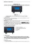
EUROSTER 2026/2026TX
1. CHARACTERISTICS
•
•
•
•
•
•
•
•
•
•
•
•
•
•
•
•
•
•
•
•
•
4 different programs for each day of the week (28 different ranges and
temperatures altogether). Time programming with 10 minutes accuracy.
Designed to operate in heating or air conditioning systems.
Temperature measurement range: 0-50 °C, resolution of 0.1 °C.
Temperature control range: 5-45 °C, resolution 0.2 °C.
Hysteresis selectable from 0.5 / 1.0 / 2.0 / 4.0 °C.
PI - system for heating curve optimization.
Sensor calibration: from -4.0 °C to 4.0 °C, step 0.2 °C.
Program copy function.
Large, clear backlit display.
Temporary temperature change - the controller instantaneously maintains the
preset temperature until the next program starts.
Holiday mode - the controller maintains the preset temperature for a selected
time up to 99 days.
Settings lock - the option to change parameters is blocked. This mode is intended
for offices where only 1 person is entitled to change the settings.
No heating, i.e. the Anti-freeze mode - the mode of heating in which the
controller maintains the lowest possible and safe temperature (5 °C); in air
conditioning mode the cooling device is disabled.
Operating time counter of the heating / air conditioning device - maximum
indication 999 hours, with a resolution of 1 minute.
Ant-freeze protection - the controller turns heating on when the temperature
drops below 5 °C. This function is always active.
Power supply: 2 AA alkaline batteries.
Output load: 16 A 230 V AC, 1-pole changeover relay.
External temperature sensor - NTC 10kΩ at 25 °C.
Automatic switch between summer and winter time.
Anti-stop system - the relay is switched on for 1 minute once a week.
Dimensions (L / H / W.): 132.5 x 85 x 27.6 mm.
CE declaration of conformity is available on the website
http://www.euroster.com.pl
EUROSTER 2026/2026TX - User Manual
2
2. PROPER PLACE FOR INSTALLATION
To ensure fully efficient controller operation, please observe the following recommendations
regarding the placement of the device.
1. The controller is designed for indoor wall mounting at a height of about 1.5 m
above the floor.
2. Avoid places with strong sunlight, near heating or cooling equipment, directly by
the doors, windows and other such locations where the temperature
measurement could be easily disturbed by external conditions.
3. Avoid areas with poor air circulation, such as behind furniture.
4. Avoid wet areas due to the negative effects of moisture on the service life of the
device.
5. Prior to installation, make sure that all repair/restoration works in the room have
been completed and the installation place is not covered with fresh paint or
plaster.
6. Levelling of the regulator is not necessary.
7. Slip excess cables back into the wall during the tuning of the device placement. In
case of draught, any gap should be filled non-combustible substance.
8. Insert the batteries, observing correct polarity.
Note! Charge a qualified installer with the installation of the controller. Do not
install the regulator showing any mechanical damages.
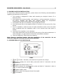
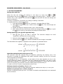
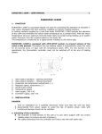
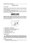
3. OUTSIDE VIEW OF THE CONTROLLER
BODY
•
•
•
•
•
•
•
and
increase / decrease, press and hold to quicken the change.
press to display the current date, press and hold for 3 seconds to set the
date and time.
toggles Anti-freeze mode (5 °C).
press to display the operating time, press and hold for 3 seconds in order to
reset, to confirm press the key
toggles Holiday mode.
.
press to select the program that will be copied.
confirmation.
EUROSTER 2026/2026TX - User Manual
3
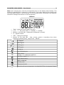
Note: Upon changing any value the corresponding item on the display starts blinking. This
should be understood as a request for confirmation. If the users approves the change with
the confirmation button, it will be stored. If not confirmed within 15 seconds, the controller
cancels the changes and returns to normal operation.
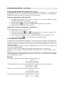
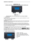
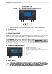
DISPLAY
•
•
•
•
•
•
“Date”- shows the current date (not time).
1,2,3, ... 7 - day of the week, 1 = Monday, 7 = Sunday.
Number on the left side - temperature (measured or preset).
°C - degrees Celsius.
“SET” - change the settings.
Number on the right side - time: current, preset or operating time (when
measuring operating time), range 00:00 - 999:59.
1st Program
2nd Program
3rd Program
4th Program
Heating on
Air Conditioning on
Time counter
(heating / air conditioning appliance)
Anti-freeze mode 5 °C
Copy function active
Battery exhausted
Holiday mode
Thermostat locked
Manual mode (preset temperature is maintained till the next program change)
EUROSTER 2026/2026TX - User Manual
4
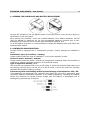
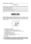
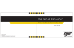
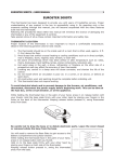
4. OPENING THE CONTROLLER AND BATTERY REPLACEMENT
Insert a flat screwdriver into the gap as shown in the figure below. Lever the lid up gently in
the direction of the front panel.
After opening the controller, insert the included batteries. Only alkaline batteries, size R6
(AA) are allowed. In particular, do not use rechargeable batteries, because (due to selfdischarge) their effective time is shorter than the alkaline batteries’ one.
To avoid negative surprises, it is recommended to replace the batteries each year before the
heating season begins.
5. CONTROLLER MODE SELECTION
Euroster 2026 is equipped with 4 configuration jumpers. Factory settings are indicated in
italics:
Installation Type: Air Condition / Heating
Jumper used to select the type of installation, in which the regulator is used.
Choice of sensor: Internal / External
Jumper used to select the sensor: internal (air temperature measured where the controller is
installed) or external (requires connection of an external sensor)
Type of algorithm: ON-OFF / P.I.
The controller can operate either in an on-off mode, in which the controller alternately turns
the heating (cooling) device on and off or in the PI mode, in which the controller smoothly
regulates the degree of heating (cooling).
Protection against overheating caused by the discharge of the batteries: YES / NO
If the batteries are discharged, the controller may switch the relay off in emergency state
(protection against uncontrolled operation of the heating appliance). Disabling this feature
causes the controller to operate without change until the battery is discharged (risk of
heating being permanently turned on).
EUROSTER 2026/2026TX - User Manual
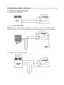
6. CONTROLLER WIRING DIAGRAM
In a system with a gas boiler
In an underfloor heating system
NOTE. If you use a floor sensor, connect it to the terminals 4 and 5. The SENSOR jumper
should also be put in the Ext position (batteries should be taken out during this procedure).
In a heating / air conditioning system
5
EUROSTER 2026/2026TX - User Manual
6
7. SETTING PARAMETERS
Setting date and time
Note: the user can confirm the settings in two ways: by using keys
or
.
Confirmation with the key
causes a jump to the next setting (Hour > Minute > Year >
Month> Day > Hour (again)). If confirmed with
, the controller will store the change and
return to operation.
If no key is pressed for 15 seconds, the change of setting is cancelled.
To set date and time, follow these steps:
1. Press and hold the
button for 3 seconds - the hour digits will flash.
2. Using
and
set the time. Confirm with the
key. The minute digits will
start flashing.
3. Repeat the steps for setting minutes, year, month and day.
4. After setting the day of the month confirm all changes hitting the
key or push
the
key to return to the settings and adjust entered values.
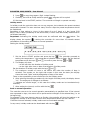
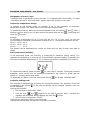
Setting Hysteresis (for ON-OFF algorithm only)
1. Hold
and
for at least 3 seconds. The controller displays the word
"Hysteresis" and shows the current setting.
Select the desired value with the
and
keys.
2.
3. Confirm with the
key or wait 15 seconds until the change is cancelled.
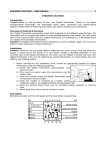
The idea behind the regulator’s operation with hysteresis is presented below:
Algorithm optimizing the heating curve (PI)
The controller 2026 can operate using an algorithm optimizing the heating curve. This
algorithm is intended for installations with water underfloor heating. Its aim is to minimize
room temperature fluctuations.
As opposed to the on / off regulation, current status of the relay depends not only on the
current difference between the preset and the measured temperature, but also on past
temperature changes. For example, if the measured temperature is lower than the preset
one for a long time, the controller turns the heating device permanently on.
In order to use the PI mode, its parameters must be set:
Minimum duration of activity ("Con") 1-5
Means the minimum time for which that the controller switches the relay on, in one cycle.
Number of cycles per hour ("CPH") 3,6,9,12
Number of switching cycles per hour. The times of activation and deactivation are calculated
by the controller.
EUROSTER 2026/2026TX - User Manual
7
Range of proportional control width ("Pb") 1.5-3.0
If the difference between the preset and the measured temperature is in the range of
proportional control, the controller calculates the times of activation and deactivation.
Outside this range, the output is turned on or off continuously.
Setting the parameters of PI algorithm
1. Hold
and
together for at least 3 seconds. The controller displays the word
"Con" and shows the current setting.
Select the desired value with the keys
and
.
2.
3. Confirm with the
key or wait 15 seconds until the change is cancelled.
4. Repeat steps 2-3 for setting "CPH" and "Pb".
Adjustment of measured temperature (calibration)
Range of calibration: from -4.0 °C to 4.0 °C.
1. Set the knob in the PN position.
2. Hold down the keys
and
simultaneously for at least 3 seconds. The
controller will show the current value of the adjustment.
Set the desired correction with the keys
and
. Step of the change is 0.2 °C.
3.
4. Confirm with the key
or wait 15 seconds to cancel the change.
8. CONTROLLER’S OPERATION
Euroster 2026 is a programmable regulator. The user can set up 4 different temperatures for
4 different intervals of time, for each day of the week separately. Setting up programs for
the entire week can be laborious; the controller is therefore equipped with the function of
copying programs.
There are 2 settings for each program: temperature and start time which also means the
end of the previous program.
During the activity of the program its assigned preset temperature is maintained.
Start time of the program is determined with an accuracy of 10 minutes. Range: 00:00 23:50.
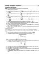
The programs are always executed in the order P1-P2-P3-P4. It is possible to set the start
times of programs in a different order than the P1-P2-P3-P4, but in this case the regulator
omits programs that overlap.
Example:
P1-4 start in sequence, the user wants P4 to begin before P3:
If P4 starts before P3, the controller automatically bypasses P3. As a result, we have:
Similarly, if a user wants to move the P2 and P3 "behind" P4:
Programs P2 and P3 are skipped (P4 starts before P2 and P3):
EUROSTER 2026/2026TX - User Manual
8
Programming the controller
Note: The order of weekdays is irrelevant during programming.
1. Set the knob at PN position.
2. Set the desired temperature for P1
key
with the keys
and
. Confirm with the
.
3. Set the required start time for P1
with the keys
and
.Confirm with the key
.
4. Set the desired temperature for P2
key
5. Set the required start time for P2
key
with the keys
and
.Confirm with the
with the keys
and
.Confirm with the
.
.
6. Similarly set temperature and time for programs P3
and P4
.
7. After setting all parameters set the knob at the next day of the week (e.g. Tuesday).
8. Set the parameters for all programs for the next day.
9. In the manner described above, set parameters for all programs for all consecutive
days, or copy the programs (see p. 14).
10. Set the knob in the START position. The controller will start to operate according to
the new settings.
Copying Programs
First, parameters for the selected programs for one day must be set, as described above.
In the following description the program from Monday is copied to Tuesday, Thursday and
Friday.
1. After setting the program for Monday (knob still at PN), press the key
.
2. The display indicates that the source of the program will be Monday:
Note: Re-pressing the key
will exit the Copy mode.
3. Select any day of the week with the knob, to which the program from Monday is to
be copied, for example Tuesday.
4. The display will indicate that the program will be copied to Tuesday: digit 2 will blink.
5. Press
to copy the program. Digit 2 stops flashing.
6. Set the knob at the next day of the week, to which the program is to be copied from
Monday, for example Thursday.
7. The display will indicate that the program is to be copied to Thursday: digit 4 will
blink.
EUROSTER 2026/2026TX - User Manual
9
8. Press
to copy the program. Digit 4 stops flashing.
9. Similarly, set knob at Friday and then press
; program will be copied.
10. Set the knob in the START position. The controller will begin to operate normally.
Holiday mode
In holiday mode the controller does not run any program, but maintains the preset constant
temperature instead. The user sets how many hours or days the preset temperature should
be maintained.
Resolution of time setting is 1 hour (in the range of up to 2 days) or 1 day (range 3-99
days). There is also a possibility to set infinite time, in which case the holiday mode must be
terminated manually.
Important: Activating the holiday mode must be confirmed with the
button. The
display shows the symbol
. Leaving the controller for more than 15 seconds causes
cancellation of the setting and return to normal operation.
Setting the holiday mode:
1. Set the knob in START position and press the key
. The controller proceeds to
setting the temperature - the temperature indication starts to flash. Set the desired
temperature with the keys
and
, to confirm press the key
or
.
2. The display will show:
- on the left side: the duration of holiday mode
- on the right side: time or date of termination of holiday mode
Set the duration of holiday mode with the keys
and
.
3. The maximum number of hours is 48. Above this value the number of days is
selected. The number on the right side means in this case the date (the display
shows the word "Date" and the designation of days of the week.
There is also a possibility to set infinite time for the holiday mode.
4. After entering the setting procedure for the length of holiday mode, the display shows
"1h". The sequence of changes is as follows:
"-" indicates an infinite length, in this case the holiday mode can be terminated only
manually.
5. After setting the interval, confirm with the key
.
Back to normal operation
The controller returns to its normal operation automatically at specified time. If the interval
was expressed in days, the return will be performed at midnight of the selected day (i.e. at
its beginning).
For example, if the user plans to return on Sunday, the controller will turn the heating on at
midnight on Sunday so as to reach normal room temperature before the user returns.
If infinite time was selected, holiday mode must be terminated manually.
In any event, holiday mode can be deactivated with the key
.
EUROSTER 2026/2026TX - User Manual
10
Designation of hours / days
If specified time is expressed in hours, the letter "h" is displayed after the number; if in days
- the display shows "d" and word "Date" appears above the number on the right.
Temporary temperature change
In contrast to the holiday mode, no duration is set in the procedure of temporary
temperature change. This mode is active until the next program starts.
To activate this feature, define the preset temperature with the buttons
and
. After 3
seconds it will be stored. You can also confirm the setting with the key
. The display will
show the
symbol.
Example:
P1 maintains a temperature of 20 °C from 9:00 am, P2 - 21 °C from 14:00. At noon the
user activates the temporary temperature change at 15 °C. The target temperature will be:
09:00 ÷ 12:00 - 20 °C
12:00 ÷ 14:00 - 15 °C
14:00 ÷ ........ - 21 °C
This feature can be deactivated by turning the knob onto any day of week, then back to
START.
Anti-freeze mode (standby)
In the anti-freeze mode, the controller is configured for maximum energy saving. If it
regulates air conditioning, it is turned off. If the controller regulates heating, it maintains the
minimum controllable temperature (5 °C) in order to prevent the installation from freezing.
To activate this feature, press and hold
for more than 3 seconds. The display contents
disappear, there remain only the measured temperature, the symbol of power and the
letters A-F, meaning Anti-freeze mode.
To deactivate this feature, the user must press the key
for at least 3 seconds again.
Controller settings lock
The controller is equipped with a function for locking the settings. The activation of the lock
is indicated by the symbol . In this case no settings can be changed. However, they can
still be displayed.
Locking the controller:
1. Set the knob in the position "SOB".
2. Hold the keys
and
together for at least 3 seconds. After 3 seconds the
regulator will be locked, and the display will show the
symbol.
3. Set the knob in the position "START".
Unlocking the controller is done in the same way.
Locking the settings does not affect the controller’s operation.
EUROSTER 2026/2026TX - User Manual
11
Checking the operating time
The controller has a function for counting of operating time of the regulated device. It is
intended to determine the date of maintenance or for cost estimation.
The maximum counted value is 999:59. The counter stops after reaching this value.
1. To display the operating time, press
.The controller displays the time of operation
and the symbol
or
, depending on which device is in operation.
2. Press the key
(return to normal operation) or perform the steps of the points 3-5
to reset the counter.
Press and hold
for 3 seconds - the digits will start to blink.
3.
4. Press
the indication will change to 000:00 and stop blinking.
5. The controller will return to normal operation after 15 seconds or after pressing
.
Anti-Stop
The controller is equipped with an anti-stop system. The controlled device (e.g. a pump) is
switched on for at least 1 minute, at least once a week, even if the controller is in the antifreeze mode. The operation is independent from programs and is not configurable.
Factory settings
Air conditioning control
Monday Friday
P1
06:00 /
P2
08:30 /
P3
15:00 /
P4
23:00 /
23
28
22
25
Saturday - Sunday
°C P1
06:00 / 23 °C
°C P2
11:00 / 22 °C
°C P3
16:00 / 23 °C
°C P4
23:00 / 25 °C
Heating control
Monday Friday
P1
06:00 /
P2
08:30 /
P3
16:00 /
P4
23:00 /
21
18
21
17
Saturday - Sunday
°C P1
08:00 / 21 °C
°C P2
08:30 / 21 °C
°C P3
15:00 / 21 °C
°C P4
23:00 / 17 °C
Hysteresis (all modes)
The hysteresis is preset at 1 °C.
Jumper settings
Factory jumper positions are as follows:
type of installation: Heating,
sensor selection: Internal,
type of algorithm: ON-OFF
protection against overheating caused by battery discharge: NO.
EUROSTER 2026/2026TX - User Manual
12
EUROSTER TXRX WIRELESS VERSION
1. GENERAL DESCRIPTION
The programmable temperature controller EUROSTER in the TXRX wireless version is, in
terms of programming, the equivalent of EUROSTER wired version. In the packaging there is
a user guide for the appropriate wired model. The difference is in how the on / off signal is
transmitted.
With the EUROSTER TXRX controller the signal is transmitted wirelessly by radio, eliminating
the need for wiring between the controller EUROSTER TX, and the device controlled by the
receiver EUROSTER RX.
The effective range of operation depends to a large extent on the materials of which the
building is made. EUROSTER TX, in conjunction with the receiver RX, provides coverage of
about 100 m in open area. In buildings this distance reaches 30 meters which means the
signal is able to cross several storeys. The signal is strongly attenuated by reinforced
concrete structures which results in significantly reduced coverage.
Low battery indicator will be visible when the battery voltage drops to a
minimum acceptable level. It is recommended to replace the batteries
with new alkaline ones, every season. If needed, the controller must be
re-programmed.
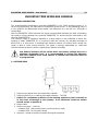
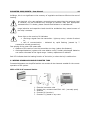
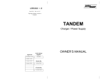
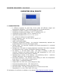
2. OUTSIDE VIEW
1. Receiving the signal from the transmitter indication- green LED
2. Receiving device (e.g. heating) activated indication - red LED
3. Switch for continuous operation of the heating appliance (can be turned on
in the event of damage to the system). In an automatic mode the switch
should remain in position 0
4. Output cable
5. Output connector - volt-free
- contacts COM - NO normally open (most commonly used)
- contacts COM - NC normally closed
6. Antenna - should be pulled out totally during the operation
EUROSTER 2026/2026TX - User Manual
13
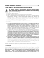
3. FIRST LAUNCH OF THE WIRELESS CONTROLLER EUROSTER TXRX
The receiver voltage is life-threatening, therefore electricity supply
should be absolutely detached during the installation and the assemblage
be entrusted to a qualified installer. Do not install the controller showing
signs of mechanical damage.
1. Insert new alkaline batteries;
2. Pull the telescopic antenna on the receiver RX out to its maximum;
3. After a few seconds the green LED should blink - the receiver is within the range of
4.
the transmitter. In order to verify coverage, after connecting the TXRX kit, the
transmitter sends a signal every 3 seconds during the first minute (green LED
blinking). Afterwards, the process is repeated every 1 minute and lasts about 1
second. No indication means insufficient coverage.
Active red LED means the heating (or cooling) device is turned on.
4. PROTECTION
1. If the receiver module EUROSTER RX does not receive a confirmation of activation or
2.
3.
deactivation during 7 consecutive cycles (due to disruption of transmission by e.g. a
strong electromagnetic pulse or due to battery voltage drop in EUROSTER TX), the
heating appliance is turned off. This prevents the device from overheating. After the
disruption is eliminated the system automatically returns to work, with the exception
of battery replacement, which requires re-programming of the TX controller.
In addition, the receiver RX is equipped with an Anti-freeze system. This function is
active only in case of loss of communication with the transmitter (discharged battery,
interference). Such a state is indicated by fast flashing of the green LED, and follows
7 consecutive missed pulses from the transmitter. If this condition persists for a
longer time, the receiver is automatically turned on for twenty minutes every three
hours, so as not to lead to cooling of the rooms. As soon as the communication is reestablished (disruption disappearance, batteries replaced) the receiver automatically
turns off and the system returns to operate with the transmitter TX.
The signal sent to EUROSTER RX has a nature of coded digital transmission. This
allows for an operation of multiple EUROSTER TX controllers on a small area without
fear of cross-interference. When using two receivers RX always keep them at least
0.5 m from each other. Controllers are always paired with receivers of the same code
and there is no possibility of exchange of a single module. The code is printed on the
receiver RX (sticker at the plug side) and the controller TX (transmitter) on the left
side of the battery compartment or on the back of the housing.
However, if doubts in this respect arise, please contact the dealer or the manufacturer
5. OPERATION
Because of the one-way signal transmission and safety of the user of heating (or cooling)
equipment, EUROSTER TX sends every minute a short coded message confirming the status
of the relay of the EUROSTER RX receiver. It is indicated by lighting of the green LED for
about 1 second. For this reason, the indicator of the controller can light up earlier than the
control device is turned on. Time difference should not be greater than 1 min. Similar
situation may occur when turning the heating appliance off. Given the heat capacity of the
EUROSTER 2026/2026TX - User Manual
14
buildings, this is not significant to the economy of regulation and has no effect on the cost of
heating.
An electrical, oil or gas appliance, consuming more power than the maximum load
of contacts, can be connected only through an external relay with appropriate
characteristics. If in doubt, please consult the distributor or manufacturer.
Large inductive and capacitive loads should be avoided as they cause burnout of
the relay’s contacts.
Green light on the receiver RX indicates:
• receiving a signal from the transmitter - lights up every 1 minute for about
1s,
• lack of communication - indicated by rapid flashing (caused by 7
consecutive missed connections).
Fast pulsing of the green LED means also
• distance of the receiver from the transmitter too long (reduce the distance).
• discharged batteries (replace with new alkaline ones). Partially discharged batteries
can cause a decrease of the signal range - battery replacement is advised.
Red LED indicates that the heating function of the boiler (or other device) is switched on.
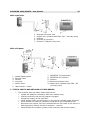
6. WIRING DIAGRAM EXAMPLE EUROSTER TXRX
Presented diagrams are simplified and do not contain all the elements needed for the correct
operation of the system.
With a 230 V AC powered device
1. Electrical connector cube
2. Output wire, contacts used COM - NO - (normally open)
3. Antenna
4. Euroster RX (receiver)
5. Euroster TX, placed in any room
EUROSTER 2026/2026TX - User Manual
15
With a gas boiler
1. Electrical connector cube
2. Output wire, contacts used COM - NO - (normally open)
3. Antenna
4. Euroster RX (receiver)
5. Euroster TX placed in any room
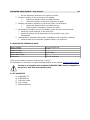
With a CH pump
1. Central heating boiler
2. Shut-off valve
3. Strainer
4. CH pump
5. Return valve
6. Heat receiver - heater
7. EUROSTER TX (transmitter)
8. EUROSTER RX (receiver)
9. Antenna
10. Electrical connector cube
11. Output wire, contacts used COM - NO
(normally open)
7. TYPICAL FAULTS AND METHODS OF THEIR REPAIR
1. The controller does not switch heating devices on:
•
•
•
•
•
•
•
replace the batteries, necessarily with new, alkaline ones;
reset the controller and set the programs up again;
change the location of the controller;
check whether LEDs (red and green) on the receiver indicate proper functions;
check whether the receiver is properly connected to the controlled device;
disconnect the receiver from the controlled device and check if the device is
working properly without the set of controller - receiver;
check whether the numbers (codes) of the controller and receiver match;
EUROSTER 2026/2026TX - User Manual
2.
3.
4.
5.
16
• pull the telescopic antenna to its maximum extent.
Rhythmic blinking of the controller’s LCD display:
•
replace the batteries with new alkaline ones;
•
reset the controller and set the programs up again.
Blinking low battery indication or word Low shown on the display
•
replace the batteries with new alkaline ones;
•
check whether the battery contacts are clean.
No activation indication on the LCD display means the device is turned off:
• check the jumper settings on the controller;
• check the settings of the parameters of the controller -day, hour,
temperature.
Heating device operates continuously, regardless of the controller’s settings:
• check whether the continuous operation switch is in position 0.
8. RECEIVER RX TECHNICAL DATA
Supply Voltage
Maximum load
Protection class
Radio frequency:
Output cable length
Dimensions
230 V AC 50/60 Hz
5 A AC
II
433.92 MHz
2m
112 x 61 x 68 mm
TXRX series products meet the EU directives: R & TTE
CE declaration of conformity is published and available on the website: www.euroster.com.pl
In case of a complaint the complete EUROSTER TXRX must be supplied to
the point of sale with the warranty card.
9. SET CONTENTS
a)
b)
c)
d)
e)
EUROSTER TX
EUROSTER RX
controller holder
user manual
alkaline batteries