1
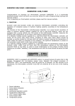
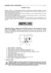
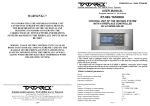
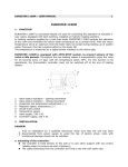
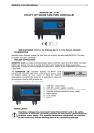
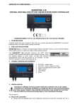
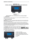
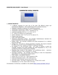
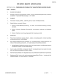
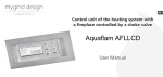
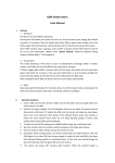
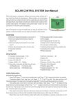
EUROSTER 1100W – USER MANUAL 1 EUROSTER 1100W 1. APPLICATION Euroster 1100W is a processor-based electronic temperature controller designed for installation on heating systems incorporating coal/ pulverised coal-fired boilers equipped with combustion blowers. In the associated hydronic heating systems the controller will operate the circulating pump and combustion blower installed under the fire box. The digital controller measures the temperature of water in the boiler and operates the pump and blower accordingly. The operating parameters include cyclic blowing time, cyclic blowing intervals and fan speed. EUROSTER 1100W is equipped with ANTISTOP system, to prevent seizure of pump rotor in idle periods. Throughout the non-heating season every fortnight the integral processor of EUROSTER 1100W will automatically cycle the pump for 30 seconds. For this function to be operational, the thermostatic controller must NOT be switched off at the end of the heating season. 1. 2. 3. 4. 5. 6. 7. 8. 9. 10. Status indication – combustion blower Status indication – circulating pump Operating mode switch, temperature adjustment – up Operating mode switch, temperature adjustment – down On/off switch for continuous pump operation On/off mains switch Power supply to blower, 230V AC Power supply to pump, 230V AC Power supply to controller unit, 230V AC Temperature sensor 2. INSTALLATION DANGER! Dangerous voltage is present both inside the enclosure and on the outgoing cables. Prior to installation by a qualified electrician make sure that the unit has been disconnected from power supply to avoid the risk of electric shock. Units with mechanical damage should not be installed. a. mounting of the controller: • the controller is fixed directly to the wall or to any other support with two screws (plastic plugs c/w screws are part of delivery) EUROSTER 1100W – USER MANUAL • 2 the cables extending from the controller are fixed to the wall with cable clips b. mounting of the temperature sensor: • the sensor is NOT intended for immersion in liquids and installation on breechings (flues between the boiler and chimney) • install the heating water temperature sensor at the special place on the boiler or on the bare outlet pipe (as close to the boiler as possible) • secure the sensor on the pipe by tightening the supplied fixing clip c. connecting of the power supply cable to the circulating pump: • • • connect the yellow or yellow/green wire (protective conductor) to terminal ( connect the blue wire to terminal (N) connect the brown wire to terminal (L) ) d. connecting of the power supply cable to the combustion blower (marked with a blue sleeve): • • • connect the yellow or yellow/green wire (protective conductor) to terminal ( connect the blue wire to terminal (N) connect the brown wire to terminal (L) ) e. check-up of connections: • make sure the connections have been made as indicated and secure the cover of the pump motor terminal box e. connection of the controller: • upon securing the cables against accidental pullout, connect the power supply cable to a 230V/50Hz grounding socket. IMPORTANT: At the mounting location of the controller ambient temperature should not exceed 40ºC. 3. OPERATION After switching on the controller allow ca. 30 sec. for the controller to become fully operational a. start up: • set the left-hand toggle switch (~) to position I • upon energising all the segments of the display light up for ca. 2 seconds • the current temperature, as measured by the sensor is displayed and the controller operates according to the factory settings (temperature limits of 50°C). b. description of display functions • display continuously on – current temperature, as measured by the sensor • blinking display – settings • red LED on – blower status • green LED on – pump status c. setting the temperatures • setting the temperature for the blower: press the left-hand switch under the display – the figures will start blinking and the current DHW temperature setpoint will be displayed • use the right-hand and left-hand switches to increase/ decrease the displayed temperature setpoint, as appropriate • after ca. 4 sec. the display will stop blinking - this indicates that the preset temperature has been stored. The display will return to displaying the current temperature, as measured by the sensor on the heating circuit. EUROSTER 1100W – USER MANUAL • • • 3 setting the temperature for the heating water circulating pump: press the righthand switch under the display – the figures will start blinking and the current DHW temperature setpoint will be displayed use the right-hand and left-hand switches to increase/ decrease the displayed temperature setpoint, as appropriate after ca. 4 sec. the display will stop blinking - this indicates that the preset temperature has been stored. The display will return to displaying the current temperature, as measured by the sensor on the heating circuit. d. blowing time adjustment • press and hold the right-hand switch until the figure to the right starts blinking. The blinking value from 0 to 9 defines the blowing time, as per the table below. • use the right-hand and left-hand switches to extend/ shorten the blowing time, as appropriate • after ca. 4 sec. the display will stop blinking - this indicates that the setpoint has been stored. The display will return to displaying the current temperature, as measured by the sensor on the heating circuit. e. blowing interval adjustment • press and hold the left-hand switch until the figure to the left starts blinking. The blinking value from 0 to 9 defines the blowing interval, as per the table below. • use the right-hand and left-hand switches to extend/ shorten the blowing interval, as appropriate, • after ca. 4 sec. the display will stop blinking - this indicates that the setpoint has been stored. The display will return to displaying the current temperature, as measured by the sensor on the heating circuit. cyclic blowing time code time 0 off 1 5sec. 2 3 4 5 6 10sec. 15sec. 20sec. 30sec. 40sec. 7 60sec. 8 80sec. 9 100sec. cyclic blowing interval code time 0 1 2 20sec. 1min. 2min. 3 4min. 4 6min. 5 8min. 6 7 8 9 10min. 12min. 14min. 16min. f. fan speed adjustment • simultaneously press the two switches under the display until double zero “00” symbol appears on the display (initially set to maximum speed). Use the toggle switches to change the code. During setting codes from 00 to 09 will appear on the display, which correspond to the blower speed settings for the operating status (blower is on). The flow rate is set with parameter, where 00 is the MAXIMUM and 01 is the MINIMUM fan speed. • use the right-hand and left-hand switches to set the desired fan speed, • after ca. 4 sec. the display will stop blinking - this indicates that the setpoint has been stored. The display will return to displaying the current temperature, as measured by the sensor on the heating circuit. g. automatic operation mode • set the right hand switch () to 0 • circulating pump - the controller will switch on the pump when the temperature measured on the sensor has exceeded the setpoint by 2°C and switch it off when the temperature has dropped by 3°C below the setpoint • combustion blower – the controller features “initial burning” function activated with the power switch. Upon each switching on the controller will check the temperature of water in the boiler. If within an hour the temperature has not risen above 30C the controller will switch off the blower (flame extinction). If the boiler temperature has risen up to the setpoint for the blower the “initial burning” mode will be switched off and the user defined settings will be applied. EUROSTER 1100W – USER MANUAL 4 The blower is switched on when the temperature has dropped by 3°C below the setpoint. Then the temperature measured by the sensor has exceeded the setpoint the switching off procedure will be initiated. The fan speed will be reduced gradually, in three steps, finished in step No. 4 when the speed is reduced to zero. When the temperature measured by the sensor has exceeded the setpoint the blower will be operated according to blowing cycles. When the measured temperature has exceeded 90°C firebox blowing will be discontinued. When the temperature has dropped below 30°C as a result of flame extinction the blower will be switched off. When the temperature has risen again the blower will be restarted (initial burning phase). h. continuous operation mode: • set the toggle switches (~) and () to position I, • the pump is continuously on, irrespective of the temperature setpoint and the current temperature, as measured by the sensor. 4. COMPLIANCE WITH STANDARDS AND CONFORMITY CERTIFICATES EUROSTER 1100W is in compliance with the following EU directives: EMC, LVD The CE certificate of conformity is posted on our website: www.euroster.com.pl 5. DATA SHEET a. b. c. d. e. f. g. h. i. j. k. l. temperature setting range temperature measurement range heating hysteresis (on / off difference) blower hysteresis (on / off difference) supply voltage maximum power of the blower maximum loading of the pump cyclic blowing time: cyclic blowing interval fan speed adjustment length of cables dimensions 40°C – 80°C 1°C – 99°C 5°C 5°C 230V AC 100 W 6A AC from 0 to 100s from 20s to 16min. from 01 to 09 1.5 m 145x72x45 Recommended fan supplier and model: WBS from Konwektor 6. SHIPPING LIST a) b) c) d) e) controller and sensor fixing clip wall plugs user manual installation template EUROSTER 1100W – USER MANUAL 5 7. WIRING DIAGRAMS These are simplified diagrams and as such they not show all the components necessary for fully functional operation of the system. wiring of EUROSTER 1100W 1. 2. 3. 4. 5. 6. 7. 8. 9. 10. 11. heating boiler expansion vessel shutoff valve strainer heating water circulating pump check valve heating unit - radiator temperature sensor EUROSTER 1100K blower fan cable marked with a sleeve