1
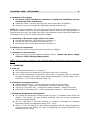
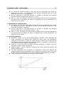
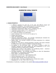
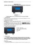
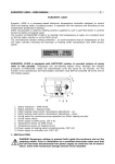
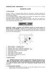
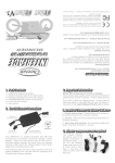
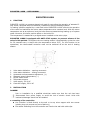
EUROSTER 1100M – USER MANUAL
1
EUROSTER 1100M
1.
FUNCTION
EUROSTER 1100M is a processor-based unit used for controlling the operation of actuated 3way valves, equipped with limit switches, installed on hydronic heating systems.
In heating systems supplied by a coal-fired boiler EUROSTER 1100M controls the operation
of the valve and maintains the return water temperature at a constant level. With the return
temperature set at an optimum level the boiler does not sweat during heating up of system
water. Moreover, this has a positive effect on the boiler life.
The temperature is measured by a digital sensor installed on the return pipe.
EUROSTER 1100M is equipped with ANTI-STOP system, to prevent seizure of the
valve in idle periods. Throughout the non-heating season it automatically cycles the valve
for 30 seconds every 14 days with the temperature below 30°C. For this function to be
operational, the thermostatic controller must not be switched off at the end of heating
season.
1.
2.
3.
4.
5.
6.
7.
8.
Valve status indication – opening movement
Valve status indication – closing movement
Hysteresis and temperature adjustment, (+)
Response speed, temperature, (–)
On/off mains switch
Temperature sensor
Valve supply, 230 V AC
Controller supply, 230 V AC
2
INSTALLATION
DANGER!
Prior to installation by a qualified electrician make sure that the unit has been
disconnected from power supply to avoid the risk of electric shock. Units with
mechanical damage should not be installed.
a. mounting of the controller:
● the controller is fixed directly to the wall or to any other support with two screws
(plastic plugs c/w screws are part of delivery)
● the cables extending from the controller are fixed to the wall with cable clips
EUROSTER 1100M – USER MANUAL
2
b. mounting of the sensor:
● the sensor is NOT intended for immersion in liquids and installation on flues
between the boiler and chimney
● install the sensor on a bare return pipe (as close to the boiler as possible)
● secure the sensor on the pipe by tightening the supplied buckle clip.
NOTE: As a recommendation, the inlet pipe should be provided with thermal insulation on
the section between the boiler and the temperature sensor. If the central heating system is
supplied by both a coal- and a gas-fired boiler, the temperature sensor should be installed at
the meeting point of the two outlet pipes and insulated.
c. connecting of the power supply cable to the valve:
● connect the black wire (valve opening) to terminal (L)
● connect the blue wire (common) to terminal (N)
● connect the brown wire (valve closing) to terminal (L)
d. check-up of connections:
● make sure that the wires have been connected as indicated
e. connection of the controller:
● upon securing the cables against accidental pullout, connect the power supply
cable to a 230V/50Hz grounding socket.
NOTE: At the mounting location of the controller ambient temperature should not exceed
40ºC.
3.
OPERATION
a. start up:
● set the left-hand switch (~) to position I,
● upon energising all the segments of the display light up for 2 seconds,
● the current temperature measured by the sensor is displayed and the controller
operates according to the factory preset values (temperature of system water: 40°C,
hysteresis: ± 1°C, neutral response speed: 16).
b. description of display functions
● display continuously on – current temperature measured by the sensor,
● blinking display – setpoints of: temperature, hysteresis, response speed,
● red LED on (the upper one) – mixing valve status indication – opening movement
● green LED on (the lower one) – mixing valve status indication – closing movement
c. setting the temperature and hysteresis
● for viewing the temperature setpoint press the right- or left-hand switch under the
display – the figures will start blinking indicating that the current temperature
setpoint is being displayed,
● use the right-hand or left-hand switches to increase or decrease the displayed
temperature within the adjustment range 10°C – 80°C,
● after ca. 4 sec. the display will stop blinking indicating that the preset temperature
has been stored. The display will return to displaying the current temperature (as
measured by the sensor).
EUROSTER 1100M – USER MANUAL
●
●
●
3
for viewing the hysteresis setpoint press and hold the right-hand switch under the
display for ca. 5 sec. – the figures will start blinking indicating that the current
temperature setpoint is being displayed,
use the right-hand or left-hand switches to increase or decrease the displayed
hysteresis within the adjustment range 0°C – 10°C,
after ca. 4 sec. the display will stop blinking indicating that the preset temperature
has been stored. The display will return to displaying the current temperature (as
measured by the sensor).
d. adjustment of response speed
● for viewing the response speed setpoint press and hold the left-hand switch under
the display for ca. 5 sec. – the figures will start blinking indicating that the current
temperature setpoint is displayed,
● use the right-hand or left-hand switches to increase or decrease the displayed
response speed within the adjustment range 1 – 64,
● after ca. 4 sec. the display will stop blinking indicating that the preset temperature
has been stored. The display will return to displaying the current temperature (as
measured by the sensor).
e. controller operation
● EUROSTER 1100M is a PI (proportional-integral) controller, which maintains the
preset temperature by opening and closing the valve. When the temperature
measured by the sensor is within the preset range the relays are off. With the two
user-defined settings: hysteresis and response speed it is possible to customise the
control algorithm to the building characteristics.
● Hysteresis – use this setting to reduce switching frequency in systems with high
variations of system water temperature
● Response speed – use this setting to customise the control speed according to the
building characteristics.
● For large exceedings and oscillations of temperature around the setpoint the
response speed should be decreased (thus increasing the response time). If the time
to reach the preset temperature is to long the response speed should be increased.
● Relation between the setpoint value and the response speed
EUROSTER 1100M – USER MANUAL
4
4. DATA SHEET
a. temperature setting range
b. temperature measurement range
c. heating system hysteresis
(turn on / turn off difference)
d. response speed
e. supply voltage
f. max. current
10°C – 80°C
1°C – 99°C
0°C – 10°C
1-64
230V AC, 50 Hz
6A AC