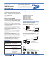
1
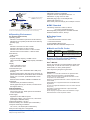
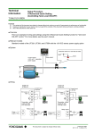
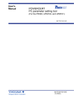
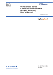
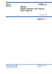
General
Specifications
LL50A Parameter Setting Software
with Ladder Program Building Function
and Network Profile Creating Function
l
tiona
Func ment
nce
Enha
GS 05P05A01-01EN
nOverview
The LL50A Parameters Setting Software is designed
to build and set parameters, program pattern, ladder
programs, and the like of the UTAdvanced digital indicating controllers from a PC. The tuning and monitoring of ladder programs are possible during communication with the controllers.
nMain Features
A Variety of Connection Methods
In addition to a connection with a Light Loader (dedicated) adapter, connections with a communication terminal
on the rear panel and a dedicated cable are available.
As for the connection with a dedicated cable, settings
can be made when the controller power is not energized.
Parameter Setting Function
This function allows for setting and changing the parameters of the controller. In case of the UT75A, allows
for setting the program pattern.
Program Pattern Setting
This function allows for setting the program patterns of UP
series program controllers. (UP55A, UP35A, and UP32A)
Creates up to 99 program patterns for UP55A and up to
4 program patterns for UP35A/UP32A.
nApplicable Controllers
UT75A digital indicating controller
UT55A digital indicating controller
UT52A digital indicating controller
UT35A digital indicating controller
UT32A digital indicating controller
UP55A program controller
UP35A program controller
UP32A program controller
UM33A digital indicator with alarms
nConnection between PC and Controller
Connection with a Dedicated Adapter
Connect the dedicated cable to the dedicated adapter
and then attach the dedicated adapter to the front of
the controller. (The adaptor cannot be used on the
controllers with the /MDL option.)
LL50A Parameter Setting Software
Light-loader
adapter
Tuning Function
This function allows for adjusting the PID parameters
while watching the PV, SP, and OUT trend graphs.
(Except UM33A)
Ladder Program Building Function
This function allows for building the input and output
signal sequences of the controller using the ladder
program. Various calculations are possible using basic
and application commands. (Except UM33A)
To USB terminal
Dedicated cable
Connection with Dedicated Cable
This connection allows for setting parameters, writing
ladder programs, and the like when the controller is not
energized.
LL50A Parameter Setting Software
Network Profile Creating Function
This function enables to create an Electronic Device
Data Sheet for PROFIBUS-DP communication.
Excluding the dual-loop type of UT32A (UT32A-D).
To USB terminal
Dedicated cable
nFunctions
Parameter setting function
* Not necessary to supply power to the UT
without the /MDL option.
Parameter setting, Display level switching
* This connection method is available even
if the controllers with the /MDL option are
energized.
Repeat action, Wait action setting
Program pattern creating PV event, Time event setting
Ladder program building function Ladder program building
Custom ladder instruction building
Program check
The contents displayed on the screen of
Custom display building function UT75A can be customized.
Monitoring function
(Necessary to supply power to the UT)
RS-485 Communication Terminal Connection
PC
Tuning, Registor monitoring
Ladder program monitoring
Network Profile Creating function Profile creating
Other functions
File management
Conserving function of CSV format
Communication processing
Upload/download
Communication comparison
Reset to factory default
Reset to user default
Communication condition setting, Print
RS-232C/
RS-485
converter
Model: Yokogawa ML2 is recommended.
Up to 31 connected slave stations with a maximum length of 1200 m
Yokogawa Electric Corporation
2-9-32, Nakacho, Musashino-shi, Tokyo, 180-8750 Japan
GS 05P05A01-01EN
©Copyright Jan. 2009 (KP)
7th Edition Mar.31, 2015 (YK)
2
Ethernet Communication Connection
Device with
Ethernet
function
Hub
Ethernet
RS-485 communication
(up to 31 units with a maximum
length of 1200 m)
Note 1: The figure shows an example
of Ethernet Serial Gateway
Function.
Dedicated Cable
USB serial converter is embeded
Compliant with the USB Specification Rev. 1.1
USB Series “A” plug on the PC side
Dedicated plug (5-pin) on the adapter side
Cable length: About 2.7 m
Note: D
irectly insert the USB plug into a USB port on the PC.
Note 1
nEMC Standard
An Ethernet connection is also possible using controllers with an RS-485 communication
function and an Ethernet/RS-485 converter (Yokogawa VJET is recommended).
nOperating Environment
PC (System Requirements)
Operating system
Windows 7 Professional (32-bit and 64-bit versions)
Windows 8.1 Pro Update (32-bit and 64-bit versions)
(Desktop type)
CPU
Pentium 4 Processor 3.0 GHz or faster
Pentium D Processor 2.6 GHz or faster
Pentium Core 2 Duo Processor 1.8 GHz or faster
Pentium Dual-Core Processor 1.6 GHz or faster
Main Memory
2 GB or more
Hard Disk
Program storage capacity: 100 MB or more
.NET Framework 4.0 SP1 storage capacity: 620 MB or
more
Display
1024 x 768 pixels or more
Color: 256 colors or more
Communication port
Communication with a dedicated cable: USB port (1
channel)
RS-485 communication: RS-232C port(1 channel). To
perform RS-422/485 communication with a connected
device, use a converter. (YOKOGAWA ML2 recommended)
Ethernet communication: 10BASE-T/100BASE-TX.
Peripherals
CD-ROM drive (to install the software.)
Printer (paper size for print: A4-size, or letter-size on
the English version.)
Dedicated Adapter
Communication method:
Non-contact, two-way, serial optical communication
on the controller side
Power supply:
Supplied from the USB bus power
Rated input voltage: 4.75 to 5.25 V DC, 100 mA DC
(including the dedicated cable)
Ambient temperature: 0 to 50°C
Ambient humidity: 20 to 90%RH (No condensation)
Transport and storage conditions:
-20 to 70°C, 5 to 90%RH (No condensation)
Dust-proof and drip-proof: Unsupported
All Rights Reserved. Copyright © 2009-2015, Yokogawa Electric Corporation
Subject to change without notice.
CE marking: EN61326-1 Class A, Table 2
(For use in industrial locations)
EMC Regulatory Arrangement in Australia and New
Zealand: EN55011 Class A, Group 1
nPackage Items
CDs: Two
LL50A software/USB conversion driver
LL50A User’s Manual
LL50A Installation Manual: One
Dedicated cable and dedicated adapter: One
nModel and Suffix Codes
Model
Suffix code
Description
LL50A
-00
Parameter Setting Software with
Ladder Program Building Function
n
Items to Specify when Ordering
Clearly state the model and suffix code.
User’s Manual
Product user’s manuals can be downloaded or viewed at the
following URL. To view the user’s manual, you need to use
Adobe Reader 7 or later by Adobe Systems.
URL: http://www.yokogawa.co.jp/ns/ut/im/
Trademarks
Windows 7 / 8.1 and .NET Framework are registered trademarks of Microsoft Corporation in the United States.
Pentium and Core 2 Duo are registered trademarks of Intel
Corporation in the United States.
Ethernet is a registered trademark of Xerox Corporation in the
United States.
PROFIBUS-DP is a registered trademark of PROFIBUS User
Organization.
CC-Link is a registered trademark of CC-Link Partner Association (CLPA.)
DeviceNet is a registered trademark of Open DeviceNet
Vender Association, Inc.
Other company and product names are trademarks or registered trade marks of their respective holders.
GS 05P05A01-01EN Mar.31, 2015-00