1
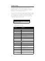
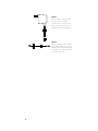
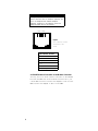
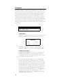
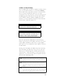
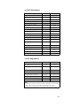
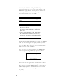
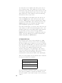
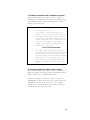
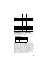
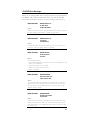
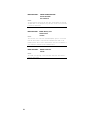
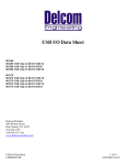
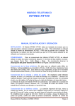
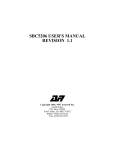
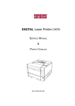
l
Sensors Division
HT100 Hand-Held Terminal
Us er's M anual
P/N 550424 Revision A
Section
TABLE OF CONTENTS
Page
1
Introduction
1
2
Basic Concepts
2
2.1 Specifications
2
3
Included Parts and Accessories
3
4
Electrical Considerations
5
4.1 Recharging the Battery
5
4.2 EIA485 Network Connection
5
4.3 RJ11 Modular Connector
5
4.4 EIA485 Network Connection to the Modular Connector
6
5
Using the Keypad
7
6
Operation
8
6.1 Main Menu
8
6.2 DDA Scan (F1 Scan)
8
6.2.1 Scan Errors
9
6.2.2 Scan Options
10
6.3 DDA/STI Setup (F2 Setup)
11
6.3.1 DDA Setup Selections
13
6.3.2 STI Setup Selections
13
6.4 DDA/STI EEPROM Utility (F3 EEPROM)
14
6.4.1 Identifying the EEPROM
15
6.4.2 Transfer Data from DDA/STI Device to HT100
15
6.4.3 Transfer Data to DDA/STI Device from the HT100
16
6.4.4 Transferring Data from a PC File to the HT100
16
6.4.5 Transfer Data to a PC File from the HT100
17
6.5 Terminal (F4 Term)
18
6.5.1 Sending Commands as ASCII Characters (F1 Option)
19
6.5.2 Sending Commands in HEX Format (F2 Option)
19
6.5.3 Sending a Two Part DDA Command
20
6.5.4 Screen Control Characters
21
6.6 Configuring a DDA or STI Address (F5 Addr)
21
6.7 Powering Down the HT100 (ESC Quit)
22
7
HT100 Error Messages
23
8
HT100 Diagnostic Functions
25
9
LCD Contrast Control
26
10
DDA Setup Notes
26
GENERAL INFORMATION
Phone Numbers: 1-800-457-6620
1-800-633-7609
919-677-0100
Fax: 919-677-0200
SHIPPING ADDRESS
HOURS
MTS SYSTEM CORPORATION
Sensors Division
3001 Sheldon Drive
Cary, North Carolina 27513
Monday - Thursday:
7:30 a.m. to 6:30 p.m. EST
Friday:
7:30 a.m. to 5:00 p.m. EST
NOT IC E:
The information contained in this manual has been reviewed for accuracy
and completeness. MTS assumes no liability resulting from errors,
omissions, or from use of information herein. MTS also assumes no
liability resulting from the use of this product. MTS reserves the right to
improve the product described in the manual, the manual itself, or the
firmware contained within the product at any time without notice.
The HT100 is warranted for two years from the start of sale to the original
purchaser except for the LCD display which is warranted for one year
only. The warranty does not cover damage caused by the misuse of the
product and is void if the cover is removed.
1.0 Introduction
The HT100 is a microprocessor based tool for use in setting up, and
troubleshooting a MTS Direct Digital Access (DDA) Level Gauge or
a MTS Side Tank Indicator (STI). At this time, the STI product is not
released for production. By using the HT100, a user can perform all
the operations necessary for maintaining a DDA/STI network. This
manual describes the operation of the HT100 in detail only and will,
at times, refer you to either the DDA or STI operation manual for
detailed information regarding the command protocol, etc.
Throughout this manual, there are various warnings, cautions, and
notes. These should be read carefully and understood fully before
using the HT100. This manual covers the HT100 programmed with
version 1.00 software only.
1
2.0 Basic Concepts
The HT100 is portable (hand held), and is provided with a
rechargeable battery (a 6V wall mount recharger is included), an
LCD display and a 45 key keypad. The LCD display is capable of
displaying the standard ASCII 96 character set.
A two-wire cable, terminated with alligator clips is provided to make
connection to the network simple. Like the DDA and STI, the HT100
uses the EIA485 data communications standard. This standard
allows multiple devices to share the same two wire network, and
communicate digitally with each other.
WARN IN G !
The HT100 is not intrinsically safe! It is not approved for
use in hazardous locations.
2.1 Specifications for HT100
Parameter
Specification
MECHANICAL
Height: 7.15 in.
Depth: 0.95 in.
Width at display: 4.1 in.
Width at keyboard: 3.5 in.
Weight: 8 oz. (w/o battery)
Storage Temperature: -4 to 158°F (-20 to 70°C)
Operating Temperature: 32 to 122°F (0 to 50°C)
Relative humidity: 0 to 90% (non-condensing)
Case construction: Molded, high-impact ABS with retractable
hanger
ELECTRICAL
Microprocessor: 87C451
Program storage: 32K "Flash" EEPROM (1000 write cycles)
Data storage: 32K battery-backed RAM
Display: 4 lines by 20 characters LCD display with 8
levels of contrast control
Keypad: 45 tactile keys
Audio: 1.5 in. speaker
Power: Rechargeable battery (8 hour capacity)
Plug-in 6V wall transformer supplied
Communication EIA485
Interface:
2
3.0 Included Parts and Accessories
The following items are included in the HT100 package.
•
•
•
•
•
•
HT100 Hand Held Terminal (Figure 1)
RJ11 Retracting / Reversing six conductor Cable (Figure 2)
Modular adapter; RJ11 to DB9 (Figure 3)
Battery Charger and DDA/STI Interface Cable (Figures 4, 5)
DDA Setup PC software on 3.5 in diskette
HT100 Operation Manual.
Figure 1
HT100 Hand held terminal unit RJ11
connector located at the base of
the unit.
RJ11
Connector
Bottom View
Figure 2
RJ11 Retracting / Reversing six
conductor cable. Connects HT100
(Fig. 1) to the modular adapter (Fig.
3).
Figure 3
Modular adapter. Converts the
RJ11 connector to a DB9 connector.
Connects the RJ11 cable (Fig.. 2) to
the DDA/STI interface cable (Fig. 5).
Accepts the plug from the battery
charger shown in (Fig. 4).
3
Figure 4
Battery charger. Plug the output
connector into the modular
connector (Fig. 3). Plug the main
body of the unit into 120 Vac. This
charger provides 6V DC @ 400 mA.
Figure 5
DDA/STI Interface cable. Connect
the Modular adapter (Fig. 3) to the
EIA485 network. Observe markings
on alligator clips when connecting
to a DDA/STI network.
4
4.0 Electrical Considerations
The HT100 has an internal rechargeable battery that will provide up
to eight (8) hours of operation when fully charged. The unit will
automatically power down after approximately 10 minutes of
inactivity on the keypad, or if no data is being received on the serial
port. The battery charger (included) can continuously power the
unit and will override the automatic power down feature.
4.1 Recharging the Battery
To recharge the HT100, plug the charger into the Modular
Adapter at the jack provided for it in the center, then
connect the RJ11 cable from the HT100 to the adapter. Plug
the transformer into a 120 Vac outlet. A full charge of the
battery can be achieved in 12 hours. Charging can be done
overnight. The charge circuit is protected from an
overcharge.
4.2 EIA485 Network Connection
To connect the HT100 to a DDA/STI network use the
interface cable provided. Attach the alligator clips to the
terminal screws found on the network safety barriers. If these
connections are not easily accessible, an alternate, more
accessible connection may need to be installed.
WARNING !
Connections should only be made to the "safe" side of
the safety barriers.
When using the interface cable (included), observe the
markings and connect the white wire labeled "RX/TX+" to
the RX/TX+ connection of the EIA485 network. Connect the
green wire labeled "RX/TX-" to the RX/TX- connection of
the EIA485 network.
The user may choose to make the network connection in
some other manner (i.e.: permanently wired into place).
Section 4.3 of this document shows the pin-outs for the
modular connector.
4.3 RJ11 Modular Connector
The six-conductor RJ11 modular connector is located at the
base of the HT100 (refer to Figure 1). This is where all
electrical connections to the unit are made -- refer to Figure
6 for the RJ11 pin outs.
5
WARN IN G !
Although the RJ11 modular connector is similar to the
modular connectors found on telephone equipment, this
unit is not compatible with standard telephone
equipment. Connection to the telephone system will
damage the HT100 and void the warranty.
1 2 3 4 5 6
Figure 6
RJ11 connector located
at the base of the
HT100
RJ11 Connector - Pin Outs
1. Power in (+6V)
2. N/C
3. RX/TX+
4. N/C
5. RX/TX6. Power supply common
4.4 EIA485 Network Connection to the Modular Connector
You may choose to make a direct connection to the EIA485
bus from the DB9 side of the modular connector. If so, use
a male DB9 connector. Connect the RX/TX+ to Pin 6 of the
DB9. Connect the RX/TX- to Pin 2 of the DB9.
6
5.0 Using the Keypad
Some of the keys on the HT100 have more than one function. Their
alternate functions are enabled when pressed in conjunction with
the <CTRL> or <SHIFT> keys. These alternate functions are
highlighted in blue or gray on the key. The characters shaded in
blue are accessible using the <CTRL> key. The characters shaded in
gray are accessible with the <SHIFT> key. For alternate key functions,
first press and hold the <CTRL> or <SHIFT> first, then the desired
key.
EXAMPLE:
ESC
Z
Escape Key
One function of this key is to exit out of a sub-menu.
Press the <SHIFT> and <ESC/Z> keys simultaneously.
Note that the 'ESC' marking on the key is highlighted in
gray. Throughout this manual, a key will be referred to
only by its functional description (i.e.: the escape key
will be referred to as <ESC>). You will know that the
<CTRL> or <SHIFT> keys need to be pressed if the
desired character or function is highlighted.
There is an audible click each time a key is pressed (except for the
<CTRL> and <SHIFT> keys). Rapid clicking indicates that an invalid
key has been pressed.
7
6.0 Operation
The HT100 software is menu driven, and simple to use. Most of the
features are available via the function keys <F1> to <F5>. To power
the unit up, press any function key. When the unit first powers up,
you will see the introduction screen on the LCD display. This
identifies the model number and software version for your unit, as
well as firmware copyright information. You may press any key to
advance past this screen, or it will continue automatically after three
seconds. Next you will see a warning screen indicating that this
device is not intrinsically safe. You must press a key to advance past
this screen.
NOT E
The term "press any key" is used here to indicate any key
except <CTRL> or <SHIFT>.
6.1 Main Menu
Once you get past the introductory screens, you will see the
Main Menu. Here you are given the following options:
MAIN MENU
F1 - Scan
F4 - Term
F2 - Set-up
F5 - Addr
F3 - EEPROM
ESC - Quit
To perform any of these functions simply press the
applicable function key. To turn the unit off, press <ESC>.
6.2 DDA Scan (F1-Scan)
The DDA Scan function allows the user to read level and
temperature data directly from a DDA gauge. Various
combinations of level and temperature data can be read at
low, medium and high resolution.
Press <F1> from the Main Menu to start the DDA Scan
function. The Scan Setup screen will be seen next. From
here you may scroll through a list of scan options by using
the <F4> and <F5> keys. A brief description of each option
will be displayed as you scroll through. See section 6.2.2 of
this document for a complete list of all scan options built
into the HT100. Refer to the DDA Gauge Operation and
Instruction Manual (P/N 550164) for a list of all DDA level /
temperature commands. Any command that is not
supported by Scan may be sent to a DDA gauge by using
the Terminal (see section 6.5).
8
When the desired option is displayed, press the <F1> key to
begin the scan. The DDA Scan display will then be seen.
The HT100 will then continuously send the command to the
DDA for the scan function you desire and display the data
on the LCD display. Update time will depend on the scan
option you have chosen. Typically, the low resolution mode
has the fastest update time, and level data is updated faster
than temperature.
6.2.1 Scan Errors
The HT100 Scan function has the ability to detect three
types of errors: "No Echo", "Bad Echo", and "No Data". The
error status is always shown on the line where "Level 1" data
is normally displayed.
"No Echo": This means that there is no gauge responding at all.
If you encounter this error, check the electrical
connections to the DDA gauge. Also verify that the
gauge address is set correctly, and that the HT100 is
set to respond to the same address as the gauge
you are trying to address. See section 6.6 of this
manual for instructions on how to modify the
address the HT100 will use. Also, verify that power is
applied to the gauge.
"Bad Echo": This means that the address and command echoed
back from the gauge did not match the address and
command sent. This error is unlikely, but could
possibly be caused by electrical noise or multiple
gauges programmed for the same address.
"No Data": This means that data expected from the DDA gauge
was not received in the allocated time frame. This
error is likely to be encountered if the DDA gauge
goes to sleep before completion of the data
transmission. Unexpected activity on the EIA485 bus
will cause a DDA gauge to go into sleep mode. This
error could also be generated if a gauge lost
adequate power before completing its data
transmission.
The DDA gauges, under certain circumstances, may
generate error codes (i.e.: Exxx). See the section on "DDA
ERROR CODES" in the DDA Operation and Instruction
Manual (P/N 550164) if you need more information. If the
DDA gauge being scanned generates an error, you will see
the resulting error code beside the parameter to which it
relates. For example, if you request Level 2 data and the
gauge is only programmed for one float (which would give
you only level 1), you will see an "E101" DDA error code
located beside the "Level 2" parameter.
9
6.2.2 Scan Options
Shown below is a list of all available scan options built into
the HT100, and the corresponding commands (in HEX).
This list is provided as a reference only, you do not have to
manually enter commands. Refer to the DDA Operation
and Instruction Manual for a complete list of details for
each command.
Command
10
Description
0A HEX
Output level 1 (product) at 0.1 inch resolution
0B HEX
Output level 1 (product) at 0.01 inch resolution
0C HEX
Output level 1 (product) at 0.001 inch resolution
0D HEX
Output level 2 (interface) at 0.1 inch resolution
0E HEX
Output level 2 (interface) at 0.01 inch resolution
0F HEX
Output level 2 (interface) at 0.001 inch resolution
10 HEX
Output level 1 (product) and level 2 (interface) at 0.1 inch
resolution
11 HEX
Output level 1 (product) and level 2 (interface) at 0.01 inch
resolution
12 HEX
Output level 1 (product) and level 2 (interface) at 0.001 inch
resolution
19 HEX
Average temperature at 1.0 degree F resolution
1A HEX
Average temperature at 0.2 degree F resolution
1B HEX
Average temperature at 0.02 degree F resolution
28 HEX
Level 1 (product) at 0.1 inch resolution, and average
temperature at 1.0 degree F resolution
29 HEX
Level 1 (product) at 0.01 inch resolution, and average
temperature at 0.2 degree F resolution
2A HEX
Level 1 (product) at 0.001 inch resolution, and average
temperature at 0.02 degree F resolution
2B HEX
Level 1 (product), level 2 (interface), at 0.1 inch resolution,
and average temperature at 1.0 degree F resolution
2C HEX
Level 1 (product), level 2 (interface), at 0.01 inch resolution,
and average temperature at 0.2 degree F resolution
2D HEX
Level 1 (product), level 2 (interface), at 0.001 inch resolution,
and average temperature at 0.02 degree F resolution
6.3 DDA / STI Setup (F2-Setup)
Both the DDA gauge and STI are capable of storing various
types of setup data internally in a nonvolatile EEPROM
device. Most of this setup data is factory set and normally
does not require modification. However, in certain
circumstances this setup data may need to be changed. For
the DDA gauge this setup data can be items like: Control
Codes, Number of Floats, Number of RTDs, Float Zero
Positions, etc. For the STI this setup data can be items like:
Control Codes, Alarm Set points, etc.
WARN IN G !
Be sure that you fully understand the effects of the
changes you plan to make before making them.
NOT E
The address for the device that you wish to modify must
match the address programmed in the HT100 prior to
performing any setup functions. See section 6.6 for
instructions on how to adjust the device address.
Press the <F2> from the Main Menu to start the Setup
function. The message on the display will ask if you want to
setup a DDA or STI device. Press <F1> to setup a DDA.
Press <F5> to set up a STI device. Press <ESC> to return to
the Main Menu.
Pressing <F1> will display the DDA setup screen. Pressing
<F5> will display the STI setup screen. Use the <F4> and
<F5> keys to scroll through the available options for the
selected device. A brief description of each option will be
displayed as you scroll through. Each description will start
with one of the following words:
Edit: Descriptions that start with the word "Edit" will allow the user
to input some value to be written to the memory device for
that unit.
Read: Descriptions that start with the word "Read" will read and
display data from a device, but will not allow the user to edit
that data. An example of this would be to read the serial
number.
Write: A description that starts with the word "Write" will write data
to the device without input from the user. The only option that
allows this is the "Write reference magnet position" option
under the DDA setup options.
11
Refer to the DDA gauge or STI manuals for additional
information about user programmable memory locations.
When you locate the desired setup option, press <F1> to
perform that function. To return to the Main Menu from
this point, press <ESC>.
After pressing <F1>, if the option description began with the
word "Edit", you will see a template for editing that data.
There will usually be a pattern enclosed in parenthesis. This
pattern will show generally how the data should be
formatted. On some items it may show the range of the
parameter. If the data contains a decimal point, the number
of digits on the left hand side of the decimal point may
vary but pay close attention to the number of digits on the
right hand side of the decimal point. If the data entered is
not just as shown in the example pattern, an error will result
when you attempt to write the data to the DDA or STI
device. See section 7.0 of this document for error message
descriptions and troubleshooting. If there is no decimal
point in the pattern, you must replace it with the exact
number of digits.
The HT100 will read the data from the DDA or STI and
display it in the edit template. To edit this data, press the
<F1> key; however, do not press the <F1> key until the data
has been received and displayed. When you press the <F1>
key, the displayed data read from the DDA or STI will be
erased and a flashing cursor will appear. Enter new data
from the keyboard, paying close attention to the pattern
provided. You may use the <BACK SPACE> key to erase
mistakes. Be aware that if you attempt to enter more
characters than will normally fit between the > < brackets,
the data will be erased. You will have to start editing over
again.
When you have finished editing the data, press the
<ENTER> key. The cursor will disappear. The display now
shows the data you have entered. To write this data to the
DDA or STI, press the <F5> key. If the data is written to the
DDA or STI device successfully, a message will appear
telling you so. If the data is not written, an error message
will appear. See section 7.0 for error message descriptions
and troubleshooting.
12
6.3.1 DDA Setup Selections
Description
Edit number of floats
Edit number of RTDs
Edit gradient
Edit Pattern
<d>
<d>
Valid Date
1 or 2
1 to 5
<d.ddddd>
7.00000 to 9.99999
Edit float #1 zero position
<dddd.ddd>
Any numeric data
Edit Float #2 zero position
<dddd.ddd>
Any numeric data
Write reference magnet position
N/A
N/A
Edit RTD #1 position
<dddd.d>
Any numeric data
Edit RTD #2 position
<dddd.d>
Any numeric data
Edit RTD #3 position
<dddd.d>
Any numeric data
Edit RTD #4 position
<dddd.d>
Any numeric data
Edit RTD #5 position
<dddd.d>
Any numeric data
Edit hardware control code
<dddddd>
Any numeric data
Edit CRC/Checksum control code
<d>
0 to 2
Edit communications time-out
timer
<d>
0 or 1
Edit temperature unit code
<d>
0 or 1
Edit linearization control code
<d>
0 or 1
Edit innage/ullage control code
<d>
0 to 2
Read serial number
N/A
N/A
Read DDA software rev. number
N/A
N/A
6.3.2 STI Setup Selections
Description
Edit Pattern
Valid Date
Edit CRC/Checksum control code
<d>
0 to 2
Edit communications time-out
timer
<d>
0 or 1
Edit alarm enabled control code
<d>
0 or 1
** Edit STI scan delay code
<d>
0 to 9 (1 to 10 sec.)
<ddd.dd>
Any numeric data
* Edit STI alarm set points
** Edit STI custom command
<ddd>
000 to 255
Read serial number
N/A
N/A
Read STI software rev. number
N/A
N/A
NOTES:
*When you select this option, you will first be asked for a tank number 1 to 8, then choose
HIGH or LOW alarm limits, and then choose a parameter (LEV1, LEV2, or TEMP).
**When you select this option, you will first be asked for a tank number 1 to 8.
13
6.4 DDA / STI EEPROM Utility (F3-EEPROM)
It is suggested that the user save the entire contents of the
EEPROM to floppy disk for archival purposes. In the event
of PCB replacement, the user can then copy the data from
the archived disk file to the new PCBs.
CAU TI ON
You should never transfer data from one DDA gauge to
another.
NOT ES
1. The HT100 can only store the contents of one device
(DDA or STI) at this time.
2. This EEPROM data is stored in RAM memory. The HT100
RAM memory is battery backed, and is retained when
power is off.
3. If data is transferred between two DDA PCBs, and the
DDA software versions are different (V1.03 and V1.04),
The float zero position and RTD position data may not
identical. Check the software version number with the
F2-Setup option.
Pressing <F3> from the Main Menu will enable the EEPROM
utility. The next message on the display will ask if you want
to use the EEPROM utility with a DDA or STI. Press <F1> to
use it on a DDA. Press <F5> to use it on a STI device. Press
<ESC> to return to the Main Menu.
Once you make your device selection, the EEPROM utility
menu will appear along with five (5) options, as follows:
EEPROM Utility
F1-HT<Dev.
F3-HT<PC
F2-HT>Dev.
F4-HT>PC
ESC-Main Menu
Notice here that the "greater than" and "less than" symbols
indicate the direction of data transfer. Options F1 and F2
allow the user to transfer EEPROM data to or from a device
(DDA or STI). Options F3 and F4 allow the user to transfer
EEPROM data to or from a PC (using DDA Setup Ver 3.01
or greater).
14
NOT E
To use options F3 and F4, you will require a PC with an
EIA485 interface and the software DDA Setup (Ver 3.02 or
greater).See the READ.ME file that is on the disk with the
DDA Setup program for details on using the program.
CAU TI ON
Do not use an EEPROM data file which was compiled
with a version of DDA Setup prior to version 3.02 with the
HT100 or DDA Setup version 3.02. The file format is
incompatible.
6.4.1 Identifying the EEPROM
There are two types of EEPROMs used on the DDA/STI
devices (X24C04 or X24C16). The HT100 will automatically
recognize the type of EEPROM that the DDA/STI is using.
When you choose the <F1> option from the EEPROM utility
menu, a message will appear indicating that the HT100 is
trying to determine the EEPROM type, then another
message will appear indicating the actual EEPROM found. If
an error message appears, see section 7.0 for error message
descriptions and troubleshooting.
6.4.2 Transfer Data from DDA/STI Device to the HT100
Press <F1> in the EEPROM utility menu. You will see the
messages described in section 6.4.1, above. If an error
message appears instead, see section 7.0 for possible causes.
Once the HT100 determines which EEPROM is in use,
another screen will appear indicating the transfer is in
progress. Notice the numbers that appear on the LCD
display. These numbers indicate the status of the transfer,
and will look something like this: >00000:050<. The five
digits on the left side of the colon indicate the address
within the EEPROM where the current data block is located.
These numbers will increment up to 00512 for the X24C04
and 02048 for the X24C16. The three digits on the right
indicate the size of the data block in bytes (data block bytes
will typically be 050 but may occasionally be 006).
The transfer time for a X24C04 is approximately 2 minutes
(512 bytes). The transfer time for a X24C16 is approximately
7 minutes (2048 bytes). You may abort the transfer at any
time by pressing <ESC>. When the transfer is completed, a
message will appear letting you know it was successful.
15
CAU
You should avoid aborting a
the data transfer, be aware
incomplete. Do not use this
TI ON
data transfer. If you do abort
that the data stored will be
data!
6.4.3 Transfer Data to DDA/STI Device from the HT100
To use this option, data must have already been transferred
to the HT100 from a DDA, STI, or PC (see section 6.4.2 or
6.4.4).
When you select the <F2> option from the EEPROM Utility
menu, a warning message will appear that asks if you are
sure that you want to overwrite the current contents of the
EEPROM memory. Press <F1> to continue. Press <F5> to
abort this function and return to the EEPROM Utility menu.
Before pressing <F1> be sure this is what you want to do or
all data stored inside the DDA or STI will be overwritten.
When you press <F1>, the transfer screen will appear. There
will also be the same status display as described in section
6.4.2 above. If you see an error message, see section 7.0 for
possible causes and troubleshooting. When the transfer is
completed, a message will appear letting you know it was
successful.
The transfer times for this option are approximately the
same as they were for transferring data from DDA/STI to
the HT100. See section 6.4.2.
6.4.4 Transferring Data from a PC File to the HT100
The DDA Setup software has an EEPROM utility which is
similar to the one built into the HT100. They are capable of
working together. To transfer data from a PC, there must be
data stored in a file on the PC (see section 6.4.5).
To load the DDA Setup PC software, after the DOS prompt,
type: DDASETUP <ENTER>. The Main Menu will appear.
Selection option 4 (DDA EEPROM Utility) from the Main
Menu. You will then see the EEPROM Menu. Select item 4
(Transfer data to an HT100 from a disk file). The PC
program will then ask for a file name. Enter the name of the
file that contains the data to send to the DDA or STI to
continue. Press <ESC> to abort the function and return to
the Main Menu. After you enter a file name, a message on
the PC screen indicates that it is ready and waiting for a
signal from the HT100.
16
On the HT100, press <F3> from the Main Menu for the
EEPROM Utility. Next, select the device type. Press <F1> for
DDA or <F5> for STI.
CAU TI ON
Do not transfer DDA data to a STI or STI data to a DDA.
The DDA or STI unit would fail to work properly, or not at
all.
You will now see the EEPROM Utility menu. Press <F3> to
receive data from the PC. The HT100 will indicate that it is
ready to receive data from the PC. Press <F1> on the HT100
to begin data transfer, or <F5> to abort. There will be a
message on the HT100 letting you know the data transfer has
begun. There will also be a display on the PC showing the
progress.
Once the data has completely been transferred, there will
be messages on both the PC and HT100 indicating that data
transfer is completed.
6.4.5 Transfer Data to a PC File from the HT100
This option will allow you to store data in a PC file that you
have transferred to the HT100 from a DDA gauge or an STI
device. Follow the steps outlined in section 6.4.2 of this
manual for instructions on how to get the data into the
HT100.
To load the DDA Setup PC software after the DOS prompt
type: DDASETUP <ENTER>. The Main Menu will appear.
From the DDA Setup Main Menu, select option 4 (DDA
EEPROM Utility). You will then see the EEPROM utility
menu. Select option 5 (Transfer data from an HT100 to a
disk file). Enter the file name you want to store the data
under. Use a name that describes the data you are saving.
(i.e.: DDA_001.DAT or STI_001.DAT).
WARN IN G!
The DDA Setup program does not check for duplicate file
names. Be sure when you name the file it is original,
otherwise the data will be overwritten.
17
To verify there are no duplicate file names, press <F1> to
view a directory listing . Press <ESC> if you want to abort
this function. Once the file name has been entered, you will
see a display indicating that the PC is ready to receive data.
There will also be a status window to show the data being
transferred as well as a byte count.
From the Main Menu of the HT100, press the <F3> key to
select the EEPROM utility. Then select the device. Press
<F1> for a DDA Gauge or <F5> for a STI unit. Press <ESC>
to return to the Main Menu. After selecting the device, the
EEPROM utility menu for the HT100 will appear. Select
option F4-HT>PC (up load data to a PC file).
Once data transfer begins, you will see data scroll across the
status window, as well as an incrementing byte count -- data
will fill the LCD screen of the HT100. Data transfer will take
less than thirty seconds, even for the larger X24C16
EEPROM. Once the data transfer is completed, the PC will
display a message indicating the transfer is finished. The
HT100 will display the EEPROM Menu.
6.5 Terminal (F4-Term)
The terminal can be used to send commands to a DDA
gauge or STI device. It can be used to receive and display
data from a DDA gauge or STI device. To start the terminal,
press <F4> from the Main Menu, you will see a blank screen
with a flashing cursor in the upper left hand corner. If there
is any activity on the EIA485 communications bus,
characters will appear on the LCD display. This mode is
useful for troubleshooting a DDA or STI system, including
software that you may be developing. All network
communication activity will be visible on the LCD display.
There is no menu display for the Terminal. The commands
for using the terminal are as follows:
F1 - Input cmd (ASCII)
F2 - Input cmd (HEX)
F3 - Clear the screen
F4 - Set DDA / STI Address
F5 - Exit Terminal, return to Main
Menu
No error checking is performed while in the terminal mode.
If you have any problems, verify that the HT100 is set for
the correct address . Press <F4> in order to set or review the
address.
18
6.5.1 Sending Commands as ASCII Characters (F1 Option)
When in the Terminal, press <F1> in order to input a
command as an ASCII character. When the prompt: "Input
cmd (ASCII):" appears, input a command as an ASCII
character via the keypad.
EXAMPLE: Communication Sequence
DDA Gauge Address: C0 HEX
In this example, use the ASCII character 'K' as the
command. For a DDA gauge, this command is a request
for the number of floats and RTDs (refer to the DDA or
STI manual for a complete list of commands). This is a
one part command, later in section 6.5.3 you will see how
to send a two part command. Once you enter the
command 'K' at the prompt, you should then see a
response similar to the following:
<C0>K<CO>K<STX>2:5<ETX>65370
This response shows the address and command you
sent, followed by the address and command echoed back
from the DDA gauge. Next is the data sent by the DDA
gauge which consists of an <STX> character followed by
the number of floats, a colon separator, and then the
number of RTDs. The data string ends with the <ETX>
character. The optional five character checksum is also
shown.
6.5.2 Sending Commands in HEX Format (F2 option)
When in the Terminal, press <F2> to input a command as a
HEX string. When the prompt: "Input cmd (HEX)" appears,
input a command as a hexadecimal number.
Follow the example in section 6.5.1 above except enter
"4B<ENTER> " instead of 'K'. Note that you must press the
<ENTER> key in this mode. You may use the <BACK
SPACE> key to correct mistakes made while entering the
command. The results are the same.
19
6.5.3 Sending a Two Part DDA Command
Section 6.5.1 describes how to transmit a one part
command with the terminal. This section will show you how
to send a two part command.
EXAMPLE: Sending a Two Part DDA Command
For this example we will send the command 41 HEX. This
is the DDA gauge command to execute a RAM test.
Again, assume the gauge address is C0 HEX. To enter the
command (part one) in an ASCII format, press <F1> and
enter 'A' at the prompt. To enter the command (part one)
in HEX format, press <F2> and press 41<ENTER>. No
matter which way you enter the command, you should
then see the following on the LCD display:
<C0>A<C0>A
This is the address and command that you sent followed
by the gauge's echo of the address and command.
Enter part two of this command is as follows:
<SOH>DDAT1<EOT>
To generate the <SOH> character, hold the <CTRL> key
and press the <A> key. To generate the <EOT> character,
hold the <CTRL> key and press the <D> key. These
characters are generated the same way on the keyboard
of a PC. The DDA should respond with:
<ACK>65530
This is the response of a DDA gauge that has
successfully completed RAM test. The optional
checksum is shown as well.
If the DDA did not successfully complete the test, you
would have seen:
<NAK>E901<ETX>ccccc
The Exxx error codes (where xxx could be any 3 digit
number) are listed in the DDA Operation Manual. The DDA
and STI operation manuals will provide a complete
references for all commands. The checksum (ccccc) is
optional.
NOT E
The DDA / STI Communication Time-out timer function
should be disabled before using the Terminal with two
part commands. Otherwise it will time out.
20
6.5.4 Screen Control Characters
Screen control characters, non-printable characters, and
any ASCII character with a value greater than 7F HEX is
replaced with text strings enclosed inside < > brackets.
These characters cannot normally be printed on the
HT100's LCD screen. Below is a listing of the codes and
corresponding replacement strings:
ASCII Code
Replacement String
Start of header
Function
0 x 01
<SOH>
Start of text
0 x 02
<STX>
End of text
0 x 03
<ETX>
End of transmission
0 x 04
<EOT>
Inquire
0 x 05
<ENQ>
Acknowledgment
0 x 06
<ACK>
Bell
0 x 07
<BELL>
Back space
0 x 08
<BS>
Horizontal tab
0 x 09
<HT>
Line feed
0 x 0A
<LF>
Vertical tab
0 x 0B
<VT>
Form feed
0 x 0C
<FF>
Carriage return (Enter key)
0 x 0D
<CR>
Negative acknowledgment
0 x 05
<NAK>
6.6 Configuring a DDA or STI Address (F5-Addr)
Each device on the EIA485 network has a distinct address
within a specified range, as follows:
Valid Address Ranges:
DDA Gauge: C0 HEX to FD HEX
STI: 80 HEX to BD HEX
Default: C0 HEX
( when HT100 is powered
up)
When you press <F5> from the Main Menu, the Address
Edit screen will appear. On the first line, the current address
will be displayed. You will enter the new address on the
second line at the blinking cursor. The new address must be
in hexadecimal, and within the ranges described above.
When the new address is entered, press <ENTER> . Use the
<BACK SPACE> to correct any mistakes. If the address is
not within the acceptable range, an error message will be
displayed. If you decide not to change the address, press
<ESC> and you will return to the Main Menu.
21
CAU TI ON
Make sure that you have the correct address entered or
a "NO ECHO" error may result, or another device may
respond in its place..
6.7 Powering Down the HT100 (ESC-Quit)
To power down the HT100, press the <ESC> from the Main
Menu. Alternately, you may press the <CTRL><F5/OFF> key
combination.
Remember, the HT100 is battery powered and will
automatically power down after a ten minute period of
inactivity on the keypad or serial port, unless the battery
charger is powering the unit.
22
7.0 HT100 Error Messages
There are several possible error messages that may be generated by
the HT100. This section will describe each one and the possible
causes and corrections. To clear an error message, press any key.
ERROR MESSAGE 1
ERROR: Address out
of range. Valid
range is 80H to FDH.
Cause:
Address is < 80H to > FDH or an invalid character was entered. To prevent
this error, make sure the address is within the valid range.
ERROR MESSAGE 2
ERROR: Address out
of range for
selected device.
Cause:
You selected a DDA device, but the address is set for an STI device or
vice versa. Select the proper address accordingly.
ERROR MESSAGE 3
ERROR: NO ECHO
No echo received
from unit.
Cause:
Four (4) possible causes:
1. The address entered into the HT100 does not match the address of any
device on the EIA485 bus.
2. The wiring to the device is damaged.
3. Power is not connected to the device.
4. Device is damaged.
ERROR MESSAGE 4
ERROR: BAD ECHO
Recv'd echo does not
match adr/cmd sent.
Cause:
This means the address or command sent back from the unit did not
match the address or command sent by the HT100. The cause may be
electrical noise on the communication bus or by two devices having
duplicate address setting.
ERROR MESSAGE 5
ERROR: NO DATA
No data was received
from the unit.
Cause:
The unit did echo correctly (if required), but did not respond with data
within the specified time frame. The most likely causes would be that
some other device on the communications bus came on and put to unit
into "sleep" mode.
23
ERROR MESSAGE 6
ERROR: BUFFER OVERFLOW
The RX data buffer
has overflowed.
Cause:
Too much data has arrived at the serial port, and the buffer has filled up.
The data buffer is only 256 bytes long. This error will not occur if the data
is limited to small blocks.
ERROR MESSAGE 7
ERROR: Memory write
failed! ACK not
received.
Cause:
This error will occur if the ACK (acknowledgment) signal is not received
from the device (DDA or STI) within the allowable time frame. If the
problem persists and no other communication errors are encountered, it
could indicate a problem with the EEPROM device.
ERROR MESSAGE 8
ERROR: invalid value
entered.
Cause:
The HT100 was expecting a value other than that which was entered -enter the value again.
24
8.0 HT100 Diagnostic Functions
Two additional functions are available from the Main Menu that are
not displayed on the LCD screen, they are:
1) LCD Test
This test will turn on each pixel on each character. This
allows you to visually inspect that the HT100 LCD is
working normally. To perform this test, go to the Main
Menu and press <CTRL><F1>. Press any key in order to
return the screen to normal.
2) ID Test
This test will transmit a string of data over the EIA485
bus (not shown on the LCD screen). The string takes the
following format:
45BPDS.aaaa.bbbb.cccc
As you can see, there are four fields. The first field
shows the unit's original manufactures part number.
(this field will always be as shown). The second field
shows the internal OTP EPROM checksum (in ASCII).
The third field shows the application code memory
checksum. The fourth and last field shows the
programming count in hex. To perform this test, press
<CTRL><F2>.
25
9.0 LCD Contrast Control
The LCD contrast can be adjusted to eight different levels. The
HT100 defaults to the highest contrast level when powered up. To
adjust the contrast, hold the <SHIFT> key then press <F5> .
10.0 DDA Setup Notes
DDA Setup (DDASETUP.EXE) is a PC software package which
performs all of the functions of the HT100, and more. The
advantage of the HT100 is its portability. The DDA Setup software is
provided to work in conjunction with the HT100 for EEPROM data
storage/retrievable.
To use this PC software, you will need a PC compatible computer
with an RS-232 port and a RS-232 to EIA485 converter (or an EIA485
port installed). The PC does not have to be connected to your
DDA/STI network, but it does need the EIA485 port to communicate
with the HT100.
The DDA Setup software is provided on a single 3.5" HD disk with
the HT100. If you need another disk size, contact MTS. See the
documentation file included on the disk (README.DOC) for
instructions on using DDASETUP.EXE.
26
l
MTS Systems Corporation
Sensors Division
3001 Sheldon Drive
Cary, North Carolina 27513
Telephone: 1-800-457-6620
Fax: 919-677-0200
09/94 550424 Revision A Printed in USA ©Copyright MTS Systems
Corporation