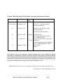
1
RAM DA-2000 Operating & Maintenance Manual Version 2.2 – September 2008 Document # PRIR44D9.DOC Version / Revision Log: RAM DA-2000 / Operating & Maintenance Manual Ver./ Rev. Date Revised Pages Comments Fourth edition September 1989 RAM DA-3 - Operation Manual, document # BN88.050 1.0 October 1996 RAM DA-3 & RAM DA-3-2000 Operating Manual, document # PWIR11D5.DOC 2.0 February 2000 2.1 August 2003 2.2 September 2008 All pages RAM DA-2000 Operating & Maintenance Manual Doc. # PRIR44D9.DOC 1, 2 Updated version, address and this log. 32 - end Appendix 2 Electronic drawings versions updated on file # PRIR44D9DRW-2.1.DOC 29 RMV software 9 Model # This manual is not to be considered a public document, and is not available for general distribution. Its distribution is limited to company employees and customer consultants of RAM series radiation meters and detectors, for the sole purpose of the RAM system operation. The contents of this manual may not be disclosed to other persons in any form, or reproduced wholly or partially, without the prior written consent of ROTEM Industries Ltd. ROTEM Industries Ltd. reserves the right to change specifications without advance notice. Ref. PRIR44D9-2.2.DOC, PRIR44D9DRW-2.2.DOC __________________________________________________________________________ RAM DA-2000/ Operating & Maintenance Manual Page 1 Table of Contents 1. 1.1. 1.2. 1.3. 1.4. General Description ............................................................................................................. 4 RAM DA-2000 Systems ........................................................................................................ 4 The RAM DA-2000 Meter..................................................................................................... 4 External Detectors.................................................................................................................. 5 RAM DA-2000 Special Advantages ...................................................................................... 7 2. Technical Data...................................................................................................................... 8 2.1. Meter ...................................................................................................................................... 8 2.2. Internal Detector .................................................................................................................... 9 3. 3.1. 3.2. 3.3. 3.4. 3.5. 3.6. 3.7. 3.8. 3.9. 3.10. 3.11. 3.12. 3.13. 3.14. Operating Instructions ...................................................................................................... 10 Preparation for Use .............................................................................................................. 10 Starting-up ........................................................................................................................... 10 Automatic Range Switching for RAM DA-3 2000 ............................................................. 11 Response Time ..................................................................................................................... 12 Units ..................................................................................................................................... 13 Changing Units .................................................................................................................... 14 General Functions ................................................................................................................ 16 External Detectors................................................................................................................ 17 Laser Bar Code Reader (optional) ....................................................................................... 17 Data Storage in the Internal Memory ................................................................................... 18 Special Functions ................................................................................................................. 18 Alarms .................................................................................................................................. 19 Replacing Batteries .............................................................................................................. 21 Push-buttons Functions ........................................................................................................ 22 4. 4.1. 4.2. 4.3. 4.4. Electronic Description ....................................................................................................... 23 Assembly Description .......................................................................................................... 23 Block Diagram ..................................................................................................................... 23 Circuits ................................................................................................................................. 24 Jumpers and Connectors Configuration ............................................................................... 25 5. 5.1. 5.2. 5.3. 5.4. 5.5. 5.6. 5.7. Calibration Instructions .................................................................................................... 26 Internal Detector & Control Switches Card ......................................................................... 26 Calibration & Linearity Check ............................................................................................. 26 Checking Geiger Muller Tubes Interchange ........................................................................ 26 Software Overflow Check.................................................................................................... 27 Calibration and Linearity Check List ................................................................................... 27 Communication Hardware ................................................................................................... 28 Relay Hardware.................................................................................................................... 28 Appendix 1 - RMV Software ........................................................................................................ 29 Appendix 2 - RAM DA-2000 - List of Electronic Drawings ........................................................ 32 Page 2 RAM DA-2000/ Operating & Maintenance Manual 1. General Description 1.1. RAM DA-2000 Systems RAM DA-2000 is the new generation of the RAM DA series. The RAM DA-2000 preserves all the functions existing in the RAM DA meters, including external detectors. The RAM DA-2000 new features are: Communication to PC, calendar/clock, nonvolatile memory, built-in bar code laser scanner (optional), SMARTS (Survey Mapping Automatic Radiation Tracking System) and RMV (Rotem Meter View) compatibility. RAM DA-2000 series includes four kinds of meters which are basically the same instruments, but differ only in the internal detector field measurement ranges: RAM DA-3-2000 : 0.5 µSv/h to 1 Sv/h (50 µR/h to 100 R/h) RAM DA-2-2000: 0.5 µSv/h to 10 mSv/h (50 µR/h to 1 R/h) RAM DA-1-2000 : 50 µSv/h to 1 Sv/h (5 mR/h to 100 R/h) RAM DA-2000 : Without internal detector This manual refers to the RAM DA-3-2000 meter, but it applies to all the RAM DA2000 series of meters. 1.2. The RAM DA-2000 Meter The RAM DA-2000 meter is designed to measure highly reliable alpha, beta, gamma and X-ray radiation measurements. The RAM DA-3-2000, a microprocessor based meter, includes an internal detector with two energy compensated GM tubes (ZP1201, ZP1313) for wide range gamma fields measurement, from 0.5 µSv/h to 1 Sv/h (50 µR/h to 100 R/h). Switching between the two GM tubes is automatically controlled by the microprocessor, according to the field level. The internal detector is active when power is on, and no external detector is connected. In case an external detector is connected to the meter, the internal G.M. is deactivated. The meter is ready for use with the external detector without recalibration or any other special procedure. When the external detector is disconnected during meter operation, the internal detector is automatically activated. When the RAM DA-2000 (without internal detector) is turned on and no external detector is connected, a DETECTOR failure alarm is activated. A large, easy to read, digital and analog LCD is integrated. The radiation rate is shown by the digital reading and auto ranging scaled bar-graph. The meter is portable and compact. It can function either as a rate meter or scaler. An audible signal indicates count rate, failure and preset threshold exceeding. Meters are available in either Seivert or Roentgen measuring units. RAM DA-2000/ Operating & Maintenance Manual Page 3 An advanced software program performs the following functions: - averaging of readings - Automatic self-test of meter and detector - Automatic detector identification for selection of correct subroutine - Automatic selection of readout units - Automatic recalibration for each change of detector - Auto ranging - Automatic recording of dose accumulation - Freeze mode to record the highest dose rate - Manually set threshold alarm - Low battery alarm - overflow alarm - Manual selection of units and functions - Compensation for detector efficiency - Compensation for detector dead time - Clock / calendar - E2EPROM for saving the meter’s parameters - Non volatile memory for data storing (option) - Communication to PC - SMARTS protocol - RMV software - relays (2 dry contacts) - built in bar-code laser scanner or bar-code pen reader (option) 1.3. External Detectors IC-10 Air-vented ionization chamber detector for beta, gamma, and X-ray fields measurements. IC-10X Air-vented ionization chamber detector for measuring X-ray narrow pulses (>50m sec). GM-10 Geiger Muller pancake detector for surface contamination monitoring of alpha, beta and gamma radiation. PA-100 Air proportional detector for alpha surface contamination monitoring, with sensitive area of 100 sq.cm. PM-10 Scintillation P.M.T. detector for X-rays and low- energy gamma radiation monitoring. Page 4 RAM DA-2000/ Operating & Maintenance Manual PM- Scintillation P.M.T. detector for alpha radiation detection. PM-11 Scintillation P.M.T. detector for high energy gamma radiation detection. GM-40 GM detector (ZP1301) for high range gamma fields (250 µSv/h to 10 Sv/h). GM-41 GM detector (ZP1313) for medium range gamma fields (50 µSv/h to 1 Sv/h). GM-42 GM detector (ZP1201) for low range gamma fields (0.5 µSv/h to 10 mSv/h). Detector type Internal detector IC-10 IC-10X PA-100 PM-a PM-10 PM-11 GM-10 GM-40 GM-41 GM-42 I.D. # 0 1 10 2 12 3 4 5 6 7 8 The detector identification number is displayed on the lower left corner of the meter display. RAM DA-2000/ Operating & Maintenance Manual Page 5 1.4. RAM DA-2000 Special Advantages Internal Detector - A detector with two energy compensated GM tubes for wide range gamma detection enables gamma radiation monitoring without external detectors. Interchangeable Detectors - External compatible detectors can be connected to the RAM DA-2000 meter as described in section 1.3. The meter automatically identifies the connected detector type and its calibration factor, and adjusts the meter readings and measuring units accordingly. Use of Ion Chamber - A unique feature is achieved by using the Ion chamber detector (IC-10) with the microprocessor based RAM system. This is possible since the signal processing in the IC-10 is done in the detector itself. An accurate voltage-to-frequency converter circuit provides the interface between the ion chamber and the microprocessor. The Ion chamber has half a liter air vented capacity, with tissue equivalent walls. Easy to Operate - Sophisticated software, large display and only five push-buttons. Convenient for training stuff. Display - Large, easy to read, digital & analog illuminated display. Easy Maintenance - An automatic self-test program initiates alarm messages in case of malfunction. The modular structure of the portable RAM DA-2000 meter enables easy maintenance. Special Operating Features: - Freeze mode enables to use the RAM DA-2000 meter as a peak detector. This feature is useful when readings must be taken in very high radiation fields where even a brief exposure can be lethal to the operator. During the freeze mode, the dose measurement continues to accumulate so that both, peak measurement and accumulated dose can be read later in a safe environment. - Dose accumulation - Select alarm threshold - Count mode with two preset periods, 100 and 1000 seconds Built-in Memory - The meter’s internal memory enables records saving. Each record includes: ID #, date, time, reading, measuring unit and detector type. PC Communication – The meter can be connected to a computer via RS-232 communication port in order to download the saved records in the meter’s memory. SMARTS & RMV – The RAM DA-2000 is SMARTS (Survey Mapping Area Radiation Tracking System) and RMV (Rotem Meter View) software compatible. Relays Output – Two relays are available. One is switched on when a threshold alarm is obtained and the other when a malfunction alarm is activated. Laser Bar-code Reader – Optional built-in laser bar-code reader is available for identification of the survey site. Page 6 RAM DA-2000/ Operating & Maintenance Manual 2. Technical Data 2.1. Meter Display LCD readout showing: a. 20-segments, auto ranging analog scaled bargraph b. Four digits for accurate and easy readout c. Two digits for type of connected detector d. Operating conditions including: Measuring units Freeze, dose, or count modes Detector failure Threshold exceeding Display illumination on/off Audible indicator on/off Low battery Operating push-buttons ON/OFF: power UNITS: units selector COUNT: start/stop SPEAKER: on/off, barcode reader LIGHT: on/off, store Measuring Units cps, cpm, counts, Sv/h, Sv (R/h, R) Other units upon request The measuring unit is automatically set for each type of detector, but can be also changed manually Power Source Three 1.5 V C-type cells - 150 hours minimum of continuous operation with alkaline batteries (excluding display lighting), using the internal detector with external detectors 100 hours - automatic battery check under full load - option, three rechargeable C-type cells and 4.5 V DC adapter/charger Memory NV RAM, stores measurement records 347 records Optional -1415 records E2EPROM – stores meter’s parameters Communication Serial communication port (RS-232) Laser Scanner Class II, maximum power 1.0 mW (for bar code) Temperature Range Operation: -10°C to +50°C (15°F to 122°F) Storage: -20°C to +60°C (-5°F to +140°F) Humidity Range 40% to 95% RH (non-condensing) RAM DA-2000/ Operating & Maintenance Manual Page 7 Casing Splash-proof plastic case Dimensions Width: 142 mm (5.6") Length: 244 mm (9.6") Height: 115 mm (4.5") Weight 1.46 Kg (3.22 lb) including batteries 2.2. Internal Detector Measuring Range 0.5 µSv/h to 1 Sv/h (50 µR/h to 100 R/h) Display Range 1 0.01 µSv/h to 1 Sv/h (1 µR/h to 100 R/h) Response Time dose rate background to 5 mSv/h 5 mSv/h to 20 mSv/h 20 mSv/h to 50 mSv/h 50 mSv/h to 200 mSv/h 200 mSv/h to 1 Sv/h Accuracy 15% of reading Energy Response137Cs 20% over the range of 60 keV to 1.2 MeV Angular Dependence137Cs 20% for 45 of preferred direction time 50 sec 30 sec 5 sec 3 sec 2 sec ____________________________________________ 1 The display range below the measuring range is indicated by two flashing arrows on the display bottom Ordering Information Without internal detector RAM DA-2000 (mR/h) BAK-1630 RAM DA-2000 (µSv/h) BAK-1640 With internal detector RAM DA-3-2000 (mR/h) BAK-1660 RAM DA-3-2000 (µSv/h) BAK-1670 Cable RAM DA Cable (coiled) BAK-0490 RAM DA Cable (straight) BAK-0510 Page 8 RAM DA-2000/ Operating & Maintenance Manual 3. Operating Instructions 3.1. Preparation for Use Remove the instruments from the shipping container and check for physical damage. In case of damage, report it immediately to the carrier. Do not attempt to install or operate damaged equipment since safety and performance may be affected 3.2. Starting-up Connect the desired detector to the meter. If no external detector is connected the internal detector will be activated. Press the ON/OFF push-button to the ON position. When the meter is turned on, it carries out a short self-test procedure indicated by displaying all the segments on the display, and emitting two beeps for a short period. Following the test, the meter is ready for use. When the self-test and adjustment program is completed the following segments are displayed (example): Bargraph Actual Reading Sv/h µ Measuring unit Audible sign I.D. # of connected detector RAM DA-2000/ Operating & Maintenance Manual Page 9 3.3. Automatic Range Switching for RAM DA-3 2000 3.3.1. Automatic internal geigers switching The internal detector includes two geigers: ZP1201 – low range geiger, ZP1313 – high range geiger In a field of 0.01 mR/h to 300 mR/h both Geigers are connected and the radiation field is measured by the low range Geiger. In case the radiation field is higher than 300 mR/h, the low range Geiger is disconnected and the radiation field is measured by the high range Geiger. Switching between low and high range Geigers is done at 300 mR/h when the radiation field increases (low range Geiger is disconnected), and at 200 mR/h when the radiation field decreases (low range Geiger is connected). The Geigers’ switching is acknowledged by three successive beeps. Geiger Type ZP 1301 High Range ZP 1201 Overflow alarm Low Range Field 0.01 mR/h 200 mR/h 300 mR/h 100 R/h 3.3.2. Audible indication while using the internal detector The field intensity audible indication rate varies continuously according to the number of pulses received from the detector. When the switching point from the low range to the high range Geiger occurs at 300 mR/h, the beeps rate drops immediately but starts increasing again according to the number of pulses received from the detector. When the switching point from the high range to the low range Geiger occurs at 200 mR/h, the beeps rate raises immediately but decreases again according to the number of pulses received from the detector. Beeps rate Field 0.01 mR/h Page 10 200 mR/h 300 mR/h RAM DA-2000/ Operating & Maintenance Manual 100 R/h 3.4. Response Time The instrument response time, according to the technical data (section 2), is adequate for slight radiation field variations. dose rate background to 5 mSv/h 5 mSv/h to 20 mSv/h 20 mSv/h to 50 mSv/h 50 mSv/h to 200 mSv/h 200 mSv/h to 1 Sv/h time 50 sec 30 sec 5 sec 3 sec 2 sec The meter software includes two functions: Smooth function - stabilizes the meter’s digital readings and is essential to avoid readings fluctuations. On the other hand, it causes long response time. Fast response function – is activated when the radiation field varies more than six times the standard variation of the previous reading. In this case, the meter response time is shorter than 2 seconds. In conclusion, the conbination of the both above functions enables fast response time and stability of the meter’s digital readings. In addition, the meter’s readings can be reset by a double press on the COUNT pushbutton. RAM DA-2000/ Operating & Maintenance Manual Page 11 3.5. Units cps - counts per second. cpm - counts per minute. Sv/h (R/h) - dose rate. Sv or R - cumulative dose since detector connection. In DOSE mode, to reset and restart accumulation press COUNT push-button twice. Dose accumulation is not performed during counts mode. Detector replace or turning the system off / on resets the accumulated dose. Example of DOSE mode reading: 100 sec. counts - scaler for counting within a period of 100 seconds. To start the count, press COUNT push-button. The bargraph shows the elapsed time, each segment flashes within the five seconds (100 sec. equals 20 segments). After the five seconds, the segment is displayed permanently. Counting and time display will stop automatically after 100 seconds or if reading exceeds 9999. The reading will be frozen. To stop and freeze the count and the clock simultaneously during the 100-second period, press COUNT push-button again. To display the elapsed time, press COUNT push-button again. To reset the counter and the time, and to start a new count, press COUNT push-button once more. Example of 100 sec. counts reading: 1000 sec. counts - same as 100 sec. counts, but stops automatically after 1000 seconds. Each segment on the bargraph indicates 50 seconds (1000 sec. equals 20 segments). Page 12 RAM DA-2000/ Operating & Maintenance Manual 3.6. Changing Units Each one of the detectors has its own default measuring unit. To change the unit, press UNITS push-button. The units selected depend on the connected detector type. Internal Detector: Default unit is Sv/h (R/h). Set threshold in Sv/h (R/h) units. Identification No. 0. Sv/h Sv 100 sec cnt 1000 sec cnt GM-10: Default unit is cps. Set threshold in cps units. Identification No. 5. cpm cps 100 sec cnt 1000 sec cnt PA-100: The same as GM-10. Identification No. 2. PM-10: The same as GM-10. Identification No. 3. PM-11: The same as GM-10. Identification No. 4. PM-: The same as GM-10. Identification No. 12. GM-40: Default unit is Sv/h (R/h). Set threshold in Sv/h (R/h) units. Identification No. 6. Sv/h Sv cps cpm 100 sec cnt 1000 sec cnt GM-41: The same as GM-40. Identification No. 7. RAM DA-2000/ Operating & Maintenance Manual Page 13 GM-42: The same as GM-40. Identification No. 8. IC-10: After the meter is turned on, the program performs an offset adjust to the probe for a period of 25 seconds. If the field intensity is less than 100 µSv/h, this adjustment is repeated automatically for 10 seconds at 5 minutes intervals. Pressing COUNT and SPEAKER push-buttons simultaneously initiates an unscheduled offset adjusment. Default unit is Sv/h (mR/h). Set threshold in Sv/h (R/h) units. Identification No. 1. µSv/h Sv mSv/h IC 10X: After the meter is turned on, the program performs an offset adjust to the probe for a period of 25 seconds. Default unit is µSv (mR) (low range). Identification No. 10. Two manually changing ranges of dose rates: Low - 1 µSv/h to 2.5 mSv/h (0.1 mR/h to 250 mR/h), High - 1 mSv/h to 250 mSv/h (100 mR/h to 25 R/h). To change from one range to another press the UNITS push-button. The OFLO (overflow) LCDs in the low range means "change to high range". In the high range mode the µSv (mR) unit blinks on the display. To change from dose (µSv or mR) to dose rate (µSv/h or mR/h) press UNITS and COUNT push-buttons simultaneously. To reset the accumulated dose (usually performed between two measurements) press COUNT push-button twice. To freeze the highest reading (dose rate only) see section 3.7d . Pressing COUNT and SPEAKER push-buttons simultaneously initiate an unscheduled offset adjustment. ON/OFF µSv Low Range UNITS µSv High Range UNITS + COUNT UNITS + COUNT µSv/h Low Range UNITS mSv/h High Range Selection of mR/h or µS/h units (this option will be available in a few months) The radiation field can be measured in mR/h or µS/h units. A long press during 10 seconds on the UNITS push-button selects between the units. When the meter is turned off, the selected unit is saved in the internal memory. Page 14 RAM DA-2000/ Operating & Maintenance Manual 3.7. General Functions a. Readout: Values are expressed in 3 digital digits and a segment: m(micro), m (mili), K (Kilo), or M (Mega), is added to the display units as required. For example: 128 µSv/h = 0.000128 Sv/h 45.8 mSv/h = 0.0458 Sv/h 1.02 K cps = 1,020 cps 1.30 M cpm = 1,300,000 cpm Note: In counts mode 4-digit values are used. For example: 1258 counts. Two flashing arrows on the display bottom indicate that the reading is below the measuring range. b. Trend by Bargraph: The measured radiation trend is shown on the bargraph. The bargraph is autoranging and shows the actual reading value. The m, m, K, M segments of the digital reading apply for the bargraph as well. While the meter is in counts mode, the bargraph shows the elapsed time. c. A Beep for Each Press: Each press on any pushbutton is acknowledged by a short beep. Press the push-buttons long enough to notice the beep sounds. d. Freeze: To freeze and show the highest reading, press the COUNT push-button while the meter is in the RATE mode (not in counts or dose mode). The freeze mode enables the operator to capture the highest reading without watching the display continuously. To cancel the freeze mode press the COUNT push-button again. The freeze mode is indicated by displaying the FREZZE segment, as shown below. e. Reading Reset: To reset the reading in rate or dose mode, press COUNT push-button twice, briefly. RAM DA-2000/ Operating & Maintenance Manual Page 15 f. Display Illumination: Press the LIGHT push-button for two seconds to turn on the display back illumination. While the light is on, the sign will be shown. The light turns off automatically after 2 minutes, or by pressing the LIGHT push-button again. g. Audible Indication: When the meter is turned on, the audible indication is activated so that the rate and trend of radiation are noticed. The sign appears on the display. To turn the audible indication off press the SPEAKER push-button for two seconds, to reactivate it press SPEAKER push-button again. Muting the audible indicator does not hold it from announcing in case of alarm. 3.8. External Detectors To use an external detector it must be connected to the meter before turning it on. When the meter is turned on , the meter identifies the connected detector type and its calibration factor set in the detector. Accordingly, the meter displays the detector ID #, the detector measurement unit and calculates the reading. When working with the RAM DA3-2000 with an external detector connected, it is possible to switch between the internal and external detectors by pressing the SPEAKER and LIGHT push-buttons simultaneously (this option will be available in a few months). 3.9. Laser Bar Code Reader (optional) a) A short press on the SPEAKER push-button operates the laser bar code reader. The bAr. LCDs is displayed and the laser beam is activated. b) If the laser bar code reader succeeds in reading the bar code label, the Go. LCDs is displayed, a beep is sounded and the laser bar code reader is turned off. c) In case the bar code reader does not read the bar code label within 3 seconds, it is turned automatically off. Note: The bar code reader cannot be operated if the communication cable is connected to the meter. d) In case the audible alarm (threshold or failure) is activated, the first short press on the SPEAKER push-button mutes the audible alarm. e) To mute the audible rate indication, perform a long press (for 2 seconds) on the SPEAKER push-button. Page 16 RAM DA-2000/ Operating & Maintenance Manual Note: If the laser bar code reader is not available a short press on the SPEAKER pushbutton mutes the audible rate indication (this option will be available in a few months). 3.10. Data Storage in the Internal Memory a) A short press on the LIGHT push-button enables to store data in the built-in NV SRAM. When data is stored, the number of available memory entries is displayed by three digits and the m segment (e.g. 345 m). Maximum memory space is 347m. The stored data includes: ID number (up-to 12 characters) Date (month, day, year) Time (hour, minutes) Measurement Unit Comments b) A long press (for 2 sec.) on the LIGHT push-button turns the light on/off. c) To transfer the saved records from the RAM DA-2000 meter to the PC, the supplied cable should be used. The SMARTS or RMV software in the PC are used to receive the meter's data. RAM DA-2000 communication protocol is adequate to SMARTS software. d) The stored data in the meter’s memory is dumped after it is transferred to the PC. Warning: Another option to erase memory is by performing a long press (for 5 sec.) on the LIGHT push-button. 3.11. Special Functions To activate Special Functions press COUNT and SPEAKER push-buttons simultaneously. To change or deactivate Special Functions press the UNITS push-button repeatedly to obtain the following sequence: CALIBRATION/OFFSET ADJUST SET THRESHOLD Out of Special Functions 3.11.1. Calibration (all detectors except IC-10) This mode is used for the detectors calibration. Calibration instructions for the internal detector can be found in section 5 and for the external detectors in the RAM DA Detectors / Service Manual. The ADJUST segment is displayed. RAM DA-2000/ Operating & Maintenance Manual Page 17 Offset Adjustment (IC-10 only): In this mode the OFFSET ADJUST segments are displayed and a 10-second automatic offset adjustment is performed. If the UNITS push-button is not pressed during this period, the program will automatically go out of Special Functions and return to its regular default measurements. To enter the SET THRESHOLD mode press the the UNITS push-button again (within the 10-second period for IC-10 only). 3.11.2. Set Threshold: The RAM DA-2000 is supplied from the company with a default threshold value set according to maximum radiation range. In order to set threshold press SPEAKER + COUNT push-buttons simultaneously to enter the Special Function mode. The ADJUST segment is displayed for the first Special Function which is CALIBRATION. To enter the SET THRESHOLD mode press UNITS push-button, the SET ALARM segment will be displayed with the default threshold value. Press SPEAKER + COUNT push-buttons simultaneously to zero the preset threshold. Use SPEAKER and COUNT push-buttons to adjust fine and coarse threshold levels respectively. When the desired value is displayed, press UNITS push-button. The system will go out of special functions, return to its regular measurement modes, and load the threshold value into the microprocessor memory. A different threshold can be set for each detector. 3.12. Alarms All the alarms are accompanied by an audible indication. To mute the audible indication press SPEAKER push-button. The adequate segment will go on flashing till the alarm cause is over. Page 18 RAM DA-2000/ Operating & Maintenance Manual a. BATTERY ALARM - If battery voltage is low, the BATTERY segment flashes on the display. Ten operation hours are remaining. b. DETECTOR ALARM - In case of defective or disconnected detector, the DETECTOR segment flashes on the display. c. OVERFLOW - In case of detector overflow, the OFLO LCDs is displayed (instead of digits). d. THRESHOLD ALARM - When reading exceeds threshold value the ALARM segment flashes on the display. RAM DA-2000/ Operating & Maintenance Manual Page 19 3.13. Replacing Batteries The meter checks the batteries voltage continuously. When the voltage is low, an audible alarm is activated and the ALARM BATTERY segment is displayed. To replace batteries, unscrew the battery compartment cover. Use three size C alkaline batteries or three C-type NiCd rechargeable batteries. Be sure to put them in the right polarity. If NiCd batteries are used, an external 4.5V DC line adaptor can be connected to the DC connector for charging the batteries. To replace the batteries from alkaline to NiCd or vise-versa, the jumper in the CPU card must be set in an authorized lab, in the following way. For alkaline batteries set jumpers E8 (1-4, 2-3). For NiCd batteries set jumpers E8 (1-2, 3-4). Notes: - External DC adaptor / charger must not exceed 5V DC. - Do not connect the line adaptor to the DC connector in case of using alkaline batteries when the unit is set to work with NiCd batteries. Figure 3-1. Batteries Compartment Page 20 RAM DA-2000/ Operating & Maintenance Manual 3.14. Push-buttons Functions Function Meter on / off Changing unit Select R/h ↔ Sv/h* Freeze Exit freeze and reset momentary readings Start / stop counts mode Operate bar-code reader Mute audible indication rate* Mute audible rate indication Mute audible alarm Store records in meter’s memory Light on / off Clear memory Special functions: - offset or calibration - set threshold value: increase most significant threshold value increase least significant threshold value Pressing Mode short short long (10 sec.) first press units: cps, cpm, mR/h, µSv/h second press units: cps, cpm, mR/h, µSv/h short units: counts short bar-code reader available short bar-code reader is not available Long (2 sec.) short short Long (2 sec.) Long (5 sec.) Push-button ON / OFF UNIT UNIT COUNT simultaneously COUNT + SPEAKER short or continuous COUNT short or continuous SPEAKER RAM DA-2000/ Operating & Maintenance Manual COUNT COUNT SPEAKER SPEAKER SPEAKER SPEAKER LIGHT LIGHT LIGHT Page 21 4. Electronic Description 4.1. Assembly Description The RAM DA-2000 meter consists of the following items: a. Plastic case (upper and lower parts) b. Meter handle c. Battery compartment d. CPU card e. Display module & display drivers card f. Internal detector and control switches card g. Cards interconnection cables h. External connectors i. Operating push-buttons 4.2. Block Diagram Display Card LCD Back-light driver Internal Detector CPU Card Push-buttons Back-light power supply Internal detector High Voltage HV & overflow testing 3 x 1.5 size C Batteries Page 22 Micro controller EPROM E²PROM NV RAM Speaker Decoder Watch-dog Latch I/O Relay RS-232 Main power supply Bar-code reader Bar-code reader power supply External detector Communication Relay contact External connectors RAM DA-2000/ Operating & Maintenance Manual 4.3. Circuits 4.3.1. CPU Card PC #1898, DRW #12480-40-00 (2 sheets) The CPU card consists of the following IC’s and functions: - micro-controller IS 80c32 (U18) - latch & EPROM 74HC373 (U12) and 27C512 (U13) - watch-dog and reset MAX 1232 (U19) - E²PROM and memory X24C04 (U6) and Dalas 1234 (U10) - decoder for chip address selection 74HC 138 (U11) - selecting between external and internal detector 74HC132 (U7) - audio indication unit: piezo electric audio element (S1), oscillator (3KH) 7555 (U8) - 2 DC supply unit one +5V main power supply, max. 756 (U21) other +5V for the laser bar-code reader, MAX 756 (U22) - RS-232 communication max 242 (U23) - laser barcode reader SE-1022 - two relays for alarm threshold and alarm failure15005 RL1 and RL2 - low battery check MAX 756 (U21) - input / ouput latch 74HC373 (U14, U16, U17) 4.3.2. Display Module (PC #1614 and PC #2023) The display module consists of a custom made LCD and three serially connected controllers (U1, U2, U3). The input data is received via U1 (pin 34) that is connected to the micro controller. The electro luminescent back light (E.L.) is mounted on the LCD rear side. 4.3.3. Internal Detector & Control Switches Card (PC #1551A) - low range GM tube (G2) ZP1201, transistors (Q3, Q4, Q11) - high range GM tube (G1) ZP1313, transistors (Q1, Q2) - calibration factors circuit: Oscillator ICM-7555 (U4), calibration trimpots (R25 low range adjust and R26 high range adjust) - overflow circuit, comparator ICL 8212 (U1) - control circuits: factor / signal selector circuit, nand's gate 4093 (U5) GM calibration factor selection, transistors (Q6, Q7, Q8) GM selection (Q5) RAM DA-2000/ Operating & Maintenance Manual Page 23 HV Supply - transformer, MICROTRAN 8050 (T1) - switching voltage regulator RV4192 (U2) - power test unit, ICL 8211 (U3) comparator Back light display circuit The electro luminescent back light (E.L.) power supply converts 5V DC to 100V AC. It consists of: - oscillator, ICM-7555 (U6) - transistors, 2N 2907 (Q9), 2N2222A (Q10) - transformer, MICROTRAN 8050 (T2) 4.4. Jumpers and Connectors Configuration Jumper Connections Jumper Pair E8 (1-4, 2-3) E8 (1-2, 3-4) E5 1-3 E7 1-3 Function Alkaline battery or external DC supply Rechargeable NiCd battery and DC charger EPROM 27C512 CPU ver. 2.0 Low battery test CPU ver. 2.0 Wiring Connections See DRW #1248-50-00 Connector # CPU Function Internal detector & control switches J1 to J2 Power, operating push-buttons, display and J4 to J1 light connections J3 Battery connector J2 Communication connector J5 Detector connector J6 Relay alarm connector Internal detector & Display control switches J3 to J1 Power, display and back light connections Page 24 RAM DA-2000/ Operating & Maintenance Manual 5. Calibration Instructions 5.1. Internal Detector & Control Switches Card U2 is used to convert +5V DC to high voltage for the Geiger tubes. Adjust TR R19 to obtain 550V ±10V on C23. Measurement is performed by means of a high voltage probe 1:1000, with input impedance of 1000 MΩ 5.2. Calibration & Linearity Check a. Use a 137Cs source of about 450 Ci.* b. Locate the meter detectors at a distance where the field intensity is 120 mSv/h. c. Bring the meter to the ADJUST mode by pressing the SPK and COUNT pushbuttons simultaneously. d. Adjust TR R26 on PC #1551A to obtain the same reading (120 mSv/h) on the meter display. Write down the reading in the results table (section 5.5). e. Press the UNITS push-button twice to return to the field measurement mode. f. Bring the meter closer to the source, to a point where the field intensity is 700 mSv/h. Write down the reading in the results table. Calculate the % error and write it down too.** g. Use a 137Cs source of about 5 Ci.* h. Locate the meter's detectors at a distance, where the field intensity is 10 mSv/h. Write down the reading in the results table. Calculate the % error and write it down too.** i. Increase the distance between the source and the monitor to a point where the field intensity is 1.5 mSv/h. j. Bring the meter to the ADJUST mode by pressing the SPK and COUNT pushbuttons simultaneously. k. Adjust TR R25 on PC #1551A to obtain the same reading (1.5 mSv/h) on the meter display. Write down the reading in the results table (section 5.5). l. Press the UNITS push-button twice to return to the field measurement mode. m. Use a 137Cs source of about 500 mCi.* n. Locate the meter's detectors at a distance, where the field intensity is 300 µSv/h. Write down the reading in the results table. Calculate the error % and write it down too.** o. Use a 137Cs source of about 50 mCi.* p. Locate the meter's detectors at a distance, where the field intensity is 10 µSv/h. Write down the reading in the results table. Calculate the error % and write it down too.** 5.3. Checking Geiger Muller Tubes Interchange a. Use a 137Cs source of about 5 Ci.* b. Field increase: Locate the meter at a distance where the field intensity is 1 mSv/h. Reduce slowly the distance between the meter and the source, till the GM RAM DA-2000/ Operating & Maintenance Manual Page 25 tubes interchange occurs which is indicated by three successive beeps. Write down the reading in the results table. Calculate the error % and write it down too. c. Field decrease: Locate the meter at a distance where the field intensity is 4 mSv/h. Increase slowly the distance between the meter and the source, till the interchange occurs which is indicated by three successive beeps. Write down the reading in the results table. Calculate the error % and write it down too. 5.4. Software Overflow Check a. Use a 137Cs source of about 450 Ci.* b. Locate the meter detectors at a distance where the field intensity is 900 mSv/h. Increase slowly the distance between the meter and the source, till the intensity is 1000 mSv/h and overflow occurs, the OFLO LCD’s is displayed accompanied with an audible indication. Write down the calculated field in the results table Notes: * The source is chosen with an activity adequate to the desired radiation field. ** Error calculation: reading - calculated field error [%] = -------------------------------- x 100 calculated field In case the error is over 10% repeat measurement or calibration procedure, or replace detector. 5.5. Calibration and Linearity Check List Results Table ZP-1313 ZP-1201 Calculated Field [mSv/h] 120 700 10 1.5 300 µ 10 µ 3 Reading [mSv/h] Error [%] 0 0 µ µ 2 OFLO Page 26 --- Comments Calibration point Linearity Linearity Calibration point Linearity Linearity GM switching Field increase GM switching Field decrease Overflow check RAM DA-2000/ Operating & Maintenance Manual 5.6. Communication Hardware RAM DA-2000 Cable 3 3 2 2 7 5 1 6 D-type 9 Pin Female D-type 9 Pin Male D-type 9 Pin 5.7. Relay Hardware RAM DA-2000 1 4 2 Relay 2 Relay 1 3 D type 9 Pin Male In case of threshold alarm Relay 1 contacts are shorted. In case of failure alarm (low bat., overflow, detector fail) Relay 2 contacts are shorted. RAM DA-2000/ Operating & Maintenance Manual Page 27 Appendix 1 Rotem Meter View Software (RMV) 1. Preface Rotem Meter View Software (RMV) is a WINDOWS based program, aimed to download ROTEM's meters measurements to a PC. The meters that comply to RMV are: RAM ION, TelePole, RamR200, AMP Meter family , DRM and RAM DA-2000. Communication between the meter and the PC can be performed in two modes: On-Line, the meter downloads the measured data into the PC at intervals time set by the user. Off-Line, data is stored in the meter (up to 347 strings) and then downloaded into the PC. 2. Required Equipment - PC based WINDOWS and RS-232 communication port. - ROTEM's customized communication cable. - ROTEM's meter. - RMV software supplied by ROTEM on ROTEM website. (www.rotemi.co.il) 3. Software Installation Follow the instruction from website 4. Operating Instructions 4.1 Connect one of ROTEM's meters to the PC via RS-232 communication port, by the customized communication cable. 4.2 Run the RMV software. • For RAM DA meter press on "Portables" • Press on "Setting , communication port" to select comm. Port and baud rate (9600) for the PC Page 28 RAM DA-2000/ Operating & Maintenance Manual 4.3 Select "Data, Get Legend "to fill the legend parameters. 5. Data Download to PC 5.1 Off Line (a) (b) Store the meter reading and date in the meter memory by a short press on the LIGHT push-button.(380 records can be store) Select "Data, Get offline" to download the meter's data. RAM DA-2000/ Operating & Maintenance Manual Page 29 5.2 On-Line (a) Press "Setting, On line Interval " to set the interval time to download the meter's data. (b) Select "Data, Start Online" to download the meter's data. (c) Select "Data, Stop Online" to stop download the meter's data. Page 30 RAM DA-2000/ Operating & Maintenance Manual General Functions (a) Setting, Parameters" • Enable set threshold alarm for the down load meter reading • Lost contact interval alarm must be bigger then On line Interval (b) "Utility , save" enable save data file (NotePad or EXCELL software) (c) "Utility , Send time" enable update meter clock& calendar. RAM DA-2000/ Operating & Maintenance Manual Page 31 Appendix 2 RAM DA-2000 List of Electronic Drawings Ref. PRIR44D9DRW-2.1.DOC Version 2.1 - August 2003 # DRW # 1 12480-40-00 2 Name PC # 4.0 CPU Card (sheet 1 of 2) 1898 12480-40-00 4.0 CPU Card (sheet 2 of 2) 1898 3 12480-40-01 3.0 CPU Card (Silk CS) 1898 4 12480-40-02 3.0 CPU Card (Silk PS) 1898 5 11220-5 5.2 Internal Detector & Control Switches 1551A 6 11220-5-01 3.0 1551 7 11220-13 2.0 RAM–DA/DA1/DA2/DA3 Internal Detector (Silk CS) RAM–DA/DA1/DA2/DA3 LCD Display 8 12480-50-00 2.1 Wiring Diagram Page 32 Ver./Rev. RAM DA-2000/ Operating & Maintenance Manual 1614 RAM DA-2000/ Operating & Maintenance Manual Page 33