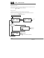
1
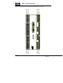
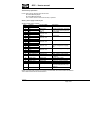
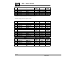
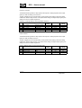
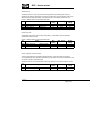
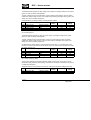
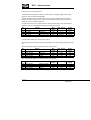
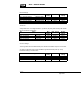
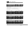
User’s manual
Generator Paralleling Controller Type GPC
multi-line 2
4189340226C
Software ver. 1.3X
DEIF A/S
• Compact system in one unit
- dynamic synchronisation
- load sharing
- generator protection
•
•
•
•
•
3-phase ACRMS measurements
Calculation of complex AC values
DIN-rail unit with separate display
Easy operator programming via display or PC
Reliable self-monitoring system
DEIF A/S
Tel: (+45) 9614 9614
Frisenborgvej 33, DK-7800 Skive Fax: (+45) 9614 9615
Denmark
E-mail: [email protected]
GPC – User’s manual
This document is the user’s manual for the standard Deif Multi-line 2 GPC.
INDEX:
WARNINGS AND LEGAL INFORMATION ................................................................................. 5
STANDARD FUNCTIONS ........................................................................................................... 5
LANGUAGE ............................................................................................................................... 5
CONTROL FUNCTIONS ............................................................................................................... 5
GENERATOR PROTECTION FUNCTIONS ........................................................................................ 6
OPTIONAL FUNCTION LIST ...................................................................................................... 6
OPTION A, MAINS FAILURE SUPERVISION..................................................................................... 6
OPTION B, BUS PROTECTION PACKAGE ..................................................................................... 6
OPTION D, VOLTAGE/VAR/POWER FACTOR CONTROL ................................................................... 6
OPTION E, ANALOGUE GOVERNOR AND AVR CONTROL OUTPUTS ................................................. 7
OPTION F1, 2 X TRANSDUCER OUTPUT ....................................................................................... 7
OPTION G, START / STOP OF NEXT GENERATOR .......................................................................... 7
OPTION H1, CAN-BUS SERIAL INTERFACE .................................................................................. 7
OPTION J1, DISPLAY CABLE, 3 M ................................................................................................ 7
OPTION J2, DISPLAY CABLE, 6 M ................................................................................................ 7
HARDWARE ............................................................................................................................... 8
TERMINAL STRIP OVERVIEW................................................................................................. 10
SLOTS 1,2,5 AND 6 ................................................................................................................. 10
SLOTS 3,4 AND 8 .................................................................................................................... 11
TERMINAL STRIP, EXPLANATION.......................................................................................... 12
SLOT #1, POWER SUPPLY AND BINARY I/O ................................................................................ 12
SLOT #2, SERIAL COMMUNICATION (OPTION H) ......................................................................... 13
CAN-bus (Option H1): ...................................................................................................... 13
SLOT #3, LOAD SHARING CONTROL .......................................................................................... 14
SLOT #4, ANALOG SPEED GOVERNOR / AVR (OPTION E) ........................................................... 16
SLOT #5, AC MEASURING........................................................................................................ 17
SLOT #6, ANALOGUE TRANSDUCER OUTPUT (OPTION F1)........................................................... 18
SLOT #8, AVR CONTROL RELAY OUTPUTS (OPTION D)............................................................... 18
WIRINGS................................................................................................................................... 19
AC CONNECTIONS .................................................................................................................. 19
LOAD SHARING LINES .............................................................................................................. 20
BINARY INPUTS ....................................................................................................................... 20
ANALOGUE INPUTS (EXTERNAL SET-POINTS) ............................................................................. 21
0…10V DC input using potentiometer: ............................................................................. 21
+/- 10V input using potentiometer:.................................................................................... 21
OPTOCOUPLER OUTPUTS FOR EXTERNAL COUNTER ................................................................... 22
DISPLAY I/F CABLE.................................................................................................................. 22
PC I/F CABLE ......................................................................................................................... 23
4189340226C
Page 2/48
GPC – User’s manual
DISPLAY UNIT.......................................................................................................................... 23
PUSH-BUTTON FUNCTIONS....................................................................................................... 24
DISPLAY FUNCTIONS ............................................................................................................... 24
First line in display (daily use display functions)................................................................ 24
Second line in display (daily use display) ......................................................................... 25
Second line in display (menu system) .............................................................................. 25
Second line in display (alarm and event list)..................................................................... 26
Third line in display (daily use display) ............................................................................. 26
Third line in display (parameter menu display) ................................................................. 26
Fourth line in display (daily use display) ........................................................................... 27
Fourth line in display (parameter menu display) ............................................................... 27
MENU OVERVIEW .................................................................................................................... 28
PASSWORD SETTING ............................................................................................................... 28
NAVIGATING IN THE MENUS ...................................................................................................... 29
Setup menu system ......................................................................................................... 29
MENU SET-POINTS.................................................................................................................. 30
PROTECTIONS ........................................................................................................................ 30
Mains/BUS voltage protection option A or B ..................................................................... 30
Mains/BUS frequency protection option A or B................................................................. 31
Generator reverse power protection ................................................................................. 32
Generator overcurrent protection...................................................................................... 32
Loss of mains protection option A..................................................................................... 32
Generator voltage protection options A and B .................................................................. 33
CONTROL FUNCTIONS ............................................................................................................. 35
Synchronisation................................................................................................................ 35
Blackout closing of breaker .............................................................................................. 35
General failure (sync fail) ................................................................................................. 35
Frequency controller ........................................................................................................ 36
Power controller ............................................................................................................... 36
Power ramp up................................................................................................................. 37
Power ramp down ............................................................................................................ 37
Power / frequency control mix factor................................................................................. 37
Voltage controller option D ............................................................................................... 38
var controller option D ...................................................................................................... 38
var / voltage control mix factor.......................................................................................... 38
Power Factor (PF) controller option D .............................................................................. 39
Load dependent start/stop of next generator option G ...................................................... 39
Nominal Settings .............................................................................................................. 40
Transformer ..................................................................................................................... 40
Controller settings ............................................................................................................ 40
CAN-bus communication enables / disables control (option H1)....................................... 41
CAN-bus communication setup (option H1)...................................................................... 41
Date and time (internal clock) setting................................................................................ 41
Battery undervoltage alarm .............................................................................................. 41
Language ......................................................................................................................... 42
ANALOGUE OUTPUT OPTION F1 ................................................................................................ 42
Power (P kW) output ........................................................................................................ 42
Apparent Power (S kVA) output........................................................................................ 42
4189340226C
Page 3/48
GPC – User’s manual
Reactive Power (Q kvar) output........................................................................................ 42
Power factor (PF) output .................................................................................................. 43
Frequency output ............................................................................................................. 43
Voltage output.................................................................................................................. 43
Current output .................................................................................................................. 43
USER PASSWORD ................................................................................................................... 44
GENERAL DATA ...................................................................................................................... 45
TECHNICAL SPECIFICATIONS .................................................................................................... 45
UNIT DIMENSIONS ................................................................................................................... 47
DISPLAY DIMENSIONS .............................................................................................................. 47
PANEL CUTOUT FOR DISPLAY ................................................................................................... 48
4189340226C
Page 4/48
GPC – User’s manual
Warnings and legal information
This manual gives guidelines to installation of the DEIF Multi-line 2 generator control and
protection units. It is, however, not a complete installation instruction. Therefore, even if terminal
numbers are shown in the drawings, the drawings are to be used as guidance only.
Installing and operating the Multi-line 2 products implies work with dangerous currents and voltages,
and therefore it should be done by qualified personnel only.
Care must be taken during installation to protect the terminals against static discharges. Once the
units is installed and connected, these precautions are no longer necessary.
DEIF takes no responsibility for operation or installation of the generator set. If there is any doubt
about how to install or operate the system on which the Multi-line 2 products are measuring, the
company responsible for installation or operation must be contacted.
Standard functions
The GPC is a control and protection unit for a generator driven by a diesel / gas engine or a
turbine. The GPC will carry out all necessary tasks to control and protect a generator, regardless
of the use of the generator. This means that the GPC can be used for several application types
such as:
Stand-alone generator
Multiple generator load sharing control
Fixed load to mains / base load
The GPC measuring system is true RMS 3-phase measurement of generator voltage, generator
current and BUS (mains) voltage.
Language
German or English language may be chosen via the system menu structure.
Control functions
-
-
Dynamic synchronisation
o Frequency matching
o Voltage check
o Breaker delay time compensation
o Check phase sequence
Fixed load (base load) running of the generator
Fixed frequency running of a stand-alone generator
Load sharing between generators with power and frequency control
Relay outputs for speed governor
Relay outputs to close / open generator breaker
Adjustable ramp up/down of generator load
Relay outputs for start / stop of next generator (high / low load)
4189340226C
Page 5/48
GPC – User’s manual
Generator protection functions
-
Reverse power
Overcurrent (2 levels)
Protective functions can be selected to activate one of 4 configurable relays.
Optional function list
Option A and option B cannot be chosen at the same time as some functions are common for
both.
Option A, mains failure supervision
-
Vector jump
Df/dt (ROCOF)
Overvoltage (2 levels)
Undervoltage (2 levels)
Overfrequency (2 levels)
Underfrequency (2 levels)
Option B, BUS protection package
-
Overvoltage (2 levels)
Undervoltage (2 levels)
Overfrequency (2 levels)
Underfrequency (2 levels)
Option D, Voltage/var/power factor control
The selection of which of the option D functions is active is dependent on the running mode
selection (mode inputs 4,5, and 6).
Please refer to I/O list for specific connection of the inputs.
4189340226C
Page 6/48
GPC – User’s manual
Option E, analogue governor and AVR control outputs
Selecting option E means that an additional board will be placed in slot #4 (terminals 65 to 72)
where 2 analogue +/- 20 mA control outputs will be present. The outputs are galvanically
separated from each other and the rest of the GPC. The outputs are active outputs (does not
require external power supply).
Option F1, 2 x transducer output
Selecting option F1 means that an additional board will be placed in slot #6 (terminals 90 to 97)
where 2 analogue 0(4)…20 mA outputs will be present. The outputs are galvanically separated
from each other and the rest of the GPC. The outputs are active outputs (does not require
external power supply). The use of the analogue outputs can be selected via the menu system or
the PC programming interface.
Option G, Start / stop of next generator
If option G is selected, relay outputs terminal 61-62 (start) and 63-64 (stop) are used. Both are
normally open relays.
The settings of level and timers can be carried out in the menu system or via PC interface.
Option H1, CAN-bus serial interface
If option H1 is selected, an additional communication board is mounted in slot #2 (terminals 2936).
For technical details regarding the CAN-bus interface, please see the CAN-bus manual.
Option J1, display cable, 3 m
Cable with male / female SUB-D plugs.
Option J2, display cable, 6 m
Cable with male / female SUB-D plugs.
4189340226C
Page 7/48
GPC – User’s manual
Hardware
The GPC unit housing is divided into board slot positions, some of which are standard (nonchangeable) and some intended for options. The unit is divided like this:
Slot #1: Standard
Slot #2:
Slot #3:
Slot #4:
Slot #5: Standard
Slot #6:
Slot #7: Not used
Slot #8:
Terminal 1-28
Terminal 29-36
Terminal 37-64
Terminal 65-72
Terminal 73-89
Terminal 90-97
Terminal 98-125
Terminal 126-133
In the standard GPC, the only slots used are as standard slot #1, #3, #5 and #8. Slots #2, #4 and
#6 are used for options, slot # 7 is not used.
Besides the slots, there is an additional board where the communication (RS 232 PC service port
for programming of setpoints and timers etc. and display) is placed.
NOTE:
For slots #1, 3 and 5, only specific boards can be mounted.
For slots #2, 4, 6 and 8, the boards are interchangeable.
An overview of the terminals can be seen on the next page.
4189340226C
Page 8/48
SLOT #5
SLOT #7
5 6
7
8 9 10 11 12 13 14
98
112 113 114 115 116 117 118 119 120 121 122 123 124 125
85 86 87 88 89
DISPLAY
126 127 128 129 130 131 132 133
90 91 92 93 94 95 96 97
65 66 67 68 69 70 71 72
51 52 53 54 55 56 57 58 59 60 61 62 63 64
Service port
29 30 31 32 33 34 35 36
15 16 17 18 19 20 21 22 23 24 25 26 27 28
79 80 81 82 83 84
99 100 101 102 103 104 105 106 107 108 109 110 111
73 74 75 76 77 78
37 38 39 40 41 42 43 44 45 46 47 48 49 50
4
er
Po
w
ok
ch
ec
k
Se
lf
SLOT #1
SLOT #3
3
Al
ar
m
inh
ibi
t
1 2
SLOT #6
SLOT #8
SLOT #2
SLOT #4
GPC – User’s manual
The slots are positioned in the unit as follows (seen from the top of the unit):
4189340226C
Page 9/48
GPC – User’s manual
Terminal strip overview
Slots 1,2,5 and 6
4189340226C
Page 10/48
GPC – User’s manual
Slots 3,4 and 8
4189340226C
Page 11/48
GPC – User’s manual
Terminal strip, explanation
For the relay outputs, following terms will be used:
NO means Normally Open
NC means Normally Closed
Com. means common terminal for the relay in question
Slot #1, power supply and binary I/O
Standard board (always needed):
Term
Function
Technical data
Description
24V DC +20 / - 30 % Power supply.
1
+24V DC
2
0V DC
3
NC
Status relay
Normally closed relay, processor
/power supply status supervision
24V / 1A
4
Com
5
NO
Relay 1,
Configurable
250V AC / 8A
6
Com.
7
NC
Relay 2,
Configurable
8
NO
250V AC / 8A
9
Com.
10
NC
11
NO
Relay 3,
Configurable
250V AC / 8A
12
Com.
13
NC
Relay 4,
Open breaker (De-load)
14
NO
250V AC / 8A
Can be configured for tripping
15
Com.
also.
16
NC
17
NO
Relay 5,
Close breaker (synchronising)
250V AC / 8A
18
Com.
19
NC
20
Open collector 1
Transistor out
Pulse output 1, kWh counter
21
Open collector 2
Transistor out
Pulse output 2, kvarh counter
22
Com.
Common
Common terminal for terminals
21 and 22
23
Digital input 1
Optocoupler
Remote alarm inhibit
24
Digital input 2
Optocoupler
Remote alarm acknowledge
25
Digital input 3
Optocoupler
Start sync. / control functions
26
Digital input 4
Optocoupler
Spare
27
Digital input 5
Optocoupler
Block loss of mains (Vector
jump and df/dt (ROCOF) only)
(option A)
28
Com
Common
Common for terminals 24 to 27
NOTE: If input terminal 25 (start sync./control) is not activated, all control functions are disabled.
This includes the terminal 43 de-load function.
4189340226C
Page 12/48
GPC – User’s manual
The GPC monitors the energy production of each unit and it has pulse outputs for kWh and
kVARh measurement. The number of pulses depends on the nominal output of the generator as
follows:
Pnom
Pnom
Pnom
< 100 kW →
100-1000 kW →
> 1000 kW →
1 pulse/kW
1 pulse/10 kW
1 pulse/100 kW
The pulse length is 1 s/pulse.
Slot #2, Serial communication (option H)
CAN-bus (Option H1):
Term.
29
30
31
32
33
34
35
36
Function
CAN-H
GND
CAN-L
CAN-H
GND
CAN-L
Not used
Not used
Description
The CAN-bus is based on CAN 2.0 B passive.
The protocol is adapted for Deif use and can
be provided. Contact Deif for further details.
4189340226C
Page 13/48
GPC – User’s manual
Slot #3, load sharing control
Term.
37
38
39
40
41
42
Function
Technical
data
-5…0…5V DC
Analogue I/O
Com
Common
-5…0…5V DC
Analogue I/O
-10…0…10V DC Analogue
input
Com
Common
-10…0…10V DC Analogue
input
43
44
Binary input 6
Binary input 7
Optocoupler
Optocoupler
45
Binary input 8
Optocoupler
46
Binary input 9
Optocoupler
47
Binary input 10
Optocoupler
48
49
50
51
52
53
54
55
56
57
58
59
60
61
62
63
64
Binary input 11
Binary input 12
Binary input 13
Binary input 14
Binary input 15
Binary input 16
Binary input 17
Binary input 18
Com
NO
Com
NO
Com
NO
Com
NO
Com
Optocoupler
Optocoupler
Optocoupler
Optocoupler
Optocoupler
Optocoupler
Optocoupler
Optocoupler
Common
Relay no. 6
250 VAC 8A
Relay no. 7
250 VAC 8A
Relay no. 8
250 VAC 8A
Relay no. 9
250 VAC 8A
Description
Active load sharing line
Common for load sharing lines
Reactive load sharing
Frequency / Active load set-point. Passive
(requires external power supply)
Common for terminals 40 and 42
Voltage /var/Power factor/Reactive load
set-point. Passive (requires external power
supply)
De-load (not possible in freq-control mode)
Manual raise speed (only active when “start
sync. /reg.” is OFF)
Manual lower speed (only active when
“start sync. /reg.” is OFF)
Manual raise voltage (only active when
“start sync. /reg.” is OFF)
Manual lower voltage (only active when
“start sync. /reg.” is OFF)
Mode 1
Mode 2
Mode 3
Mode 4
Mode 5
Mode 6
Generator breaker open
Generator breaker closed
Common for terminals 43 to 55
Engine speed governor: Raise speed
Engine speed governor: Lower speed
Start next generator (high load)
Stop next generator (low load)
NOTE: The terminal 43 de-load function will ramp the generator down and open the breaker. If
the function is left ON after opening of breaker, it will prevent re-synchronisation.
Mode 1-6: These controls are only active when the breaker is closed and the "activate controls"
input is ON.
Control selections with mode 1-6 inputs: See next page
4189340226C
Page 14/48
GPC – User’s manual
Power / frequency
mode selection
Fixed frequency
Base load (Fixed Power)
Droop
Load sharing
Mode 1
Mode 2
OFF
ON
OFF
ON
OFF
OFF
ON
ON
Power / frequency modes
Internal set-point
External (terminals 40(signal) and 41(gnd))
set-point
External set-point values:
Mode
Input
Fixed frequency
-10…0…+10V DC
Base load (Fixed Power) 0…10V DC
Droop
-10…0…+10V DC
Load sharing
-10…0…+10V DC
Voltage/var/power
factor mode selection
(option D)
Fixed voltage
Fixed var control
Fixed power factor
control
var sharing
Mode 3 OFF
Mode 3 ON
Value
- 5…0…+5 Hz related to nominal frequency
0…100% load related to nominal power
- 5…0…+5 Hz related to nominal frequency
- 5…0…+ 5Hz related to nominal frequency
Mode 4
Mode 5
OFF
ON
OFF
OFF
OFF
ON
ON
ON
Voltage/var/power factor modes (option D)
Internal set-point
External (terminals 41(signal) and 42(gnd))
set-point
Mode 6 OFF
Mode 6 ON
External set-point values:
Mode
Input
Fixed voltage
-10…0…+10V DC
Fixed var control
0…10V DC
Fixed power factor
0…+10V DC
control
var sharing
-10…0…+10V DC
Value
- 10…0…+10 % related to nominal voltage
0…100% load related to nominal power
Cos ϕ 1.0…0.6 inductive
- 10…0…+10 % voltage setting related to
nominal voltage
External set point inputs are passive and require an external power source (+/- 10 VDC)
4189340226C
Page 15/48
GPC – User’s manual
Slot #4, Analog speed governor / AVR (option E)
These outputs are active outputs i.e. they use the internal power supply. The outputs are
galvanically separated from each other and the rest of the unit.
The current outputs can if needed be converted to voltage using a resistor across the terminals
(250 Ω will convert the +/- 20 mA into +/- 5 VDC).
Term.
65
66
67
68
69
70
71
72
Note1):
Function
Not used
+/- 20 mA out
0
Not used
Not used
+/- 20 mA out
0
Not used
Description
Speed governor set-point output.
AVR voltage set-point output.1)
Voltage control set-point to AVR is an option (option F).
If the combination of analogue speed governor signals and relay AVR signals
(or vice versa) is needed, the analog signal is carried out using the slot #4
analogue output and relay output control is carried out with relay 6/7 (speed) or
8/9 (voltage) in slot #3.
4189340226C
Page 16/48
GPC – User’s manual
Slot #5, AC measuring
Term.
73
74
75
76
77
78
79
80
81
82
83
84
85
86
87
88
89
Note:
Function
I L1 s1
I L1 s2
I L2 s1
I L2 s2
I L3 s1
I L3 s2
U L1
U L2
U L3
U Neutral
U L1
U L2
U L3
Technical description
Generator current L1
Description
1/5 A AC input.
Generator current L2
1/5 A AC input.
Generator current L3
1/5 A AC input.
Generator voltage L1
Not used
Generator voltage L2
Not used
Generator voltage L3
Generator voltage
neutral
BUS voltage L1
Not used
BUS voltage L2
Not used
BUS voltage L3
Max. 690 VAC phase - phase value
Max. 690 VAC phase - phase value
Max. 690 VAC phase - phase value
For land-based applications only.
Max. 690 VAC phase - phase value
Max. 690 VAC phase - phase value
Max. 690 VAC phase - phase value
Current inputs are galvanically separated. Max. 0.3 VA per phase.
Voltage measurements are available in 4 levels:
100 to 110V AC
200 to 240V AC
380 to 480V AC
660 to 690V AC
Voltage level to be defined when ordering, but can be changed onsite.
4189340226C
Page 17/48
GPC – User’s manual
Slot #6, analogue transducer output (option F1)
These outputs are active outputs i.e. they use the internal power supply. The outputs are
galvanically separated from each other and the rest of the unit. The individual output can be
selected (in display or via PC programming software) to represent any AC measuring value and
related values (e.g. power, power factor, frequency, etc….).
For actual selection refer to the programming manual.
Via software selection, the outputs can be selected to be 0…20 mA or 4…20 mA.
The current output can if needed be converted to voltage using a resistor across the terminals
(250 Ω will convert the 0 - 20 mA into 0 - 5V DC).
The outputs can, by moving a jumper on the board, be selected to be +/- 20 mA if needed.
Term.
Slot #6
90
91
92
93
94
95
96
97
Function
Not used
0(4) - 20 mA out
0
Not used
Not used
(4) - 20 mA out
0
Not used
Description
Analogue output, selectable.
Analogue output, selectable.
Slot #8, AVR control relay outputs (option D)
Term.
Slot #6
126
127
128
129
130
131
132
133
Function
Technical data
Description
NO
Com
NO
Com
Not used
Not used
Not used
Not used
Relay 10
250V AC, 8A
Relay 11
250V AC, 8A
AVR voltage increase
AVR voltage decrease
4189340226C
Page 18/48
GPC – User’s manual
Wirings
AC connections
BU SBA R
L2
L3
L1
N
PPU
8 9 U L3
8 7 U L2
BU SBA R
V O LTA G E
8 5 U L1
18
19
BR EA KER
ON
15
16
BR EA KER
O FF
84 N
8 3 U L3
8 1 U L2
s2
s1
s2
7 9 U L1
78
I3
77
76
s1
I2
75
s2
74
s1
G EN ER A TO R
V O LTA G E
G EN ER A TO R
C U RR EN T
I1
73
G EN ER A TO R
Notes:
The neutral line (N) connection is not necessary for correct measurement. 3phase without neutral is also possible.
The current transformers ground connection can be on s1 or s2 connection,
whichever is preferred.
Fuses: 2A slow-blow.
4189340226C
Page 19/48
GPC – User’s manual
Load sharing lines
Even though screened cable is not needed, it is recommended if the cable run is longer than 5 m
between units.
Binary inputs
All binary inputs are 24 VDC bi-directional optocoupler. Typical input is:
4189340226C
Page 20/48
GPC – User’s manual
Analogue inputs (external set-points)
The set-point inputs are passive, i.e. an external power source is needed. This can be an active
output from e.g. a PLC, or a potentiometer can be used.
0…10V DC input using potentiometer:
+/- 10V input using potentiometer:
4189340226C
Page 21/48
GPC – User’s manual
Optocoupler outputs for external counter
The kWh counter (terminals 21-23) and kvarh counter (terminals 21-22) outputs are low-power
outputs. For that reason the following circuit must be applied:
+ 24 VD C
EX TER N A L
C O U N TER
0 .5 u F
100V
PPU
2 0 (kW h)
2 2 (C O M M O N )
O VD C
Display I/F cable
A standard computer extension cable can be used (9-pole SUB-D male / female plugs) or a cable
can be tailored:
Wires min 0.22 mm2, max cable length 3m.
Cable types: Belden 9540, BICC H8146, Brand Rex BE57540 or equivalent.
4189340226C
Page 22/48
GPC – User’s manual
PC I/F cable
A standard computer null-modem cable can be used (9-pole SUB-D female / female plugs) or a
cable can be tailored:
Display unit
The display unit used in multi-line 2 communicates and receives power supply via a 9-pole Sub-D
plug. The plug fits directly onto the main unit, so the display can be mounted on the top of the
main unit.
If the display is to be used as remote display, a standard computer extension cable with male /
female plug can be used for the connection.
Display dimensions HxWxD = 115 x 220 x 20 mm
4189340226C
Page 23/48
GPC – User’s manual
Push-button functions
There are 10 pushbuttons on the display unit with the following functions:
INFO:
Shifts the display 3 lower lines to show the alarm list (up to 30 alarms can be in the
list).
JUMP:
Enters a menu number selection. All settings have a specific number attached to it.
Using the JUMP button enables the user to select and display any setting without
navigating all the way through the menus (see later).
VIEW:
Shifts the upper line displaying. The following values can be shown:
3 generator voltages (phase-to-phase)
3 BUS voltages (phase-to-phase)
3 generator currents
Generator power factor and produced power (kW)
Generator apparent power (VA) and reactive power (kvar)
Generator L1 frequency and voltage
BUS L1 frequency and voltage
-
LOG:
Shifts the display 3 lower lines to show the event and alarm list
:
Moves the cursor left for manoeuvring in the menus.
:
Increases the value of the selected set-point (in the setting menus). In the daily use
display it is used for scrolling the second line displaying of generator values.
SEL:
Is used to select the chosen function (underscored selection in the lower line of the
display).
:
ESC:
:
Decreases the value of the selected set-point (in the setting menus). In the daily use
display it is used for scrolling the second line displaying of generator values.
Jumps backwards one step in the menu (to previous display).
Moves the cursor right for manoeuvring in the menus.
Display functions
First line in display (daily use display functions)
The first line is used to display generator and BUS values. Typically the line will show 2 or 3
different values at the same time The following line values can be seen:
4189340226C
Page 24/48
GPC – User’s manual
- Generator voltage L1 L2 L3 (VAC)
- BUS voltage L1 L2 L3 (VAC)
- Generator current L1 L2 L3 (A)
- Generator Power Factor and active power (kW)
- Generator apparent power (kVA) and reactive power (kvar)
- Generator L1 frequency (Hz) and voltage (VAC)
- BUS L1 frequency (Hz) and voltage (VAC)
Second line in display (daily use display)
The second line is a service line where various values can be shown. Scrolling is done using the
and
keys. The values available are:
For generator:
For BUS:
voltage L1-N (VAC)
voltage L2-N (VAC)
voltage L3-N (VAC)
voltage L1-L2 (VAC)
voltage L2-L3 (VAC)
voltage L3-L1 (VAC)
voltage max. (VAC)
voltage min. (VAC)
current L1 (A)
current L2 (A)
current L3 (A)
frequency L1 (Hz)
frequency L2 (Hz)
frequency L3 (Hz)
active power (kW)
reactive power (kvar)
apparent power (kVA)
energy counter (kWh)
power factor
voltage angle between L1-L2 (deg.)
voltage angle between L2-L3 (deg.)
voltage angle between L3-L1 (deg.)
voltage L1-N (VAC)
voltage L2-N (VAC)
voltage L3-N (VAC)
voltage L1-L2 (VAC)
voltage L2-L3 (VAC)
voltage L3-L1 (VAC)
voltage max. (VAC)
voltage min. (VAC)
frequency (Hz)
voltage angle between L1-L2 (deg.)
frequency deviation (df/dt) (Hz / sec.)
voltage angle between generator voltage
and BUS voltage (deg.)
power supply voltage (VDC)
Second line in display (menu system)
When entering the menu system, the second line in the display is used for information about
which function (with function identifying number) is chosen.
Using the
and
keys will scroll through the settings.
4189340226C
Page 25/48
GPC – User’s manual
Second line in display (alarm and event list)
When selecting the alarm (and event) list, the second line will display the latest alarm / event.
Using the
and
keys will scroll through the list.
Third line in display (daily use display)
The third line is an indication line. If no system messages are shown (e.g. “Synchronising”), the
third line contains an explanation for the lower line selection of setup.
Third line in display (parameter menu display)
In the parameter menu, the third line indicates the present setting of the function in question, and,
if changes are to be made, the max. and min. possible value for the setting.
4189340226C
Page 26/48
GPC – User’s manual
Fourth line in display (daily use display)
In the daily use display, the fourth line is the entry selection for the parameter menu. If “SEL” is
pressed, the selection of menu indicated with an underscore will be entered.
Choices are:
“PROT”, protection setup
“CTRL”, controls setup
“POWER”, power control setup
“SYST”, system setup
The settings related to the setup can be seen in the paragraph “Menu overview”, where the
specific function numbers (related to the “JUMP” function) can be seen.
Fourth line in display (parameter menu display)
When entering the parameter menus, the first (entry) display uses the fourth line to select a subfunction for the parameter. What the selections are is dependent on the function selected.
Examples:
For protective function, the first entry shows the “BUS high volt 1” setting (provided the option is
chosen). In this case the fourth line shows:
“LIM”, setting of switch point
“DEL”, setting of time delay
“RL”, selection of which relay the function must activate.
“ACT”, activate / de-activate the function.
For control functions, the first entry shows the “Sync. To BUS” function. In this case the fourth
line shows:
“fMax”, max. allowed positive frequency deviation when synchronising.
“fMin”, min allowed negative frequency deviation when synchronising.
“Umax”, max. allowed voltage deviation (positive or negative) when synchronising.
“tCB”, closing time delay for generator circuit breaker.
For power setup, the first entry shows the “Load dependent start” relay output (if the option is
chosen). In this case the fourth line shows:
“LIM”, setting of load dependent start output activation limit.
“DEL”, time delay for activating the relay.
“ACT”, activate / de-activate the function.
Note that no relay selection is present. This is due to the fact that the function relates to a predetermined relay output.
4189340226C
Page 27/48
GPC – User’s manual
For system setup, the first entry shows the “Nominal settings”. In this case the fourth line shows:
“F”, nominal frequency setting.
“P”, nominal generator power setting.
“PF”, nominal generator power factor setting.
“U”, nominal generator voltage setting.
The above settings are used by the GPC to calculate nominal apparent power and current.
Menu overview
The following is the menu structure when entering settings of the GPC. If no entry has taken
place before, the first display to appear is the password display. Enter the factory setting
password to gain access to the menus.
If no actions have been taken within 30 seconds, the password entry will be de-activated, and a
new password entry will be needed.
The menu overview is divided according to the daily use display selections in the fourth line
(“PROT”, “CTRL”, “POWER”, “SYST”.)
Password setting
The password setting falls outside the menu structure and can only be entered via the “JUMP”
pushbutton.
Select no. 4976 to enter password setting and select your own password. Use the
and the
buttons to change the setting and the “SEL” button to store the new setting. Beware: Write
down the new password. If you forget it entering the menus will not be possible.
4189340226C
Page 28/48
GPC – User’s manual
Navigating in the menus
The menu navigating starts from the daily use display fourth line and is carried out from there
using the “SEL”,
,
,
,
and “ESC” pushbuttons.
Setup menu system
The following is an example, but all menus operate in the same manner.
Starting from the daily use display fourth line, select the menu indicated with underscore:
(move the underscore with the
and
pushbuttons)
PROT CTRL POWER SYST
ESC
SEL
1010 BUS high-volt 1
Set point
103.0 %
1020 BUS high-volt 2
Set point
105.0 %
LIM DEL
LIM DEL
RL ACT
….ETC.
RL ACT
ESC
SEL
First
entry?
Yes
No
Enter passw.
ENTER
1011 BUS high-volt 1
100.0 103.0 120.0 %
RESET
SAVE
1932
increase no.
decrease no.
increase setting
decrease setting
and
moves the selection (underscore)
4189340226C
Page 29/48
GPC – User’s manual
Menu set-points
The following lists are in numerical order, i.e. the set-points and timers appear acc. to the given
number.
Protections
Mains/BUS voltage protection option A or B
Voltage selections relate to nominal phase – to phase voltage
No.
Setting
Min.
setting
1010 BUS high volt 1
Selection display
1011 BUS high volt 1
Set-point
100.0%
1012 BUS high volt 1
Time
0.0s
1013 BUS high volt 1
Relay output
R0 (None)
1014 BUS high volt 1
Relay output
R0 (None)
1015 BUS high volt 1
Enable
OFF
No.
1020
1021
1022
1023
1024
1025
Setting
BUS high volt 2
BUS high volt 2
BUS high volt 2
BUS high volt 2
BUS high volt 2
BUS high volt 2
No.
1030
1031
1032
1033
1034
1035
No.
1040
1041
1042
1043
1044
1045
Max. setting
Selection display
Set-point
Time
Relay output
Relay output
Enable
Max. setting
Selection display
Set-point
Time
Relay output
Relay output
Enable
Min.
setting
80.0%
0.0s
R0 (None)
R0 (None)
OFF
Max. setting
Selection display
Set-point
Time
Relay output
Relay output
Enable
Min.
setting
80.0%
0.0s
R0 (None)
R0 (None)
OFF
Setting
BUS low volt 2
BUS low volt 2
BUS low volt 2
BUS low volt 2
BUS low volt 2
BUS low volt 2
120.0%
100.0s
R4 (relay 4)
R4 (relay 4)
ON
Min.
setting
100.0%
0.0s
R0 (None)
R0 (None)
OFF
Setting
BUS low volt 1
BUS low volt 1
BUS low volt 1
BUS low volt 1
BUS low volt 1
BUS low volt 1
Max. setting
120.0%
100.0s
R4 (relay 4)
R4 (relay 4)
ON
100.0%
100.0s
R4 (relay 4)
R4 (relay 4)
ON
100.0%
100.0s
R4 (relay 4)
R4 (relay 4)
ON
Factory
setting
103.0%
10.0s
R2 (relay 2)
R0 (None)
OFF
Factory
setting
105.0%
5.0s
R1 (relay 1)
R0 (None)
OFF
Factory
setting
97.0%
10.0s
R2 (relay 2)
R0 (None)
OFF
Factory
setting
95.0%
5.0s
R1 (relay 1)
R0 (None)
OFF
4189340226C
Page 30/48
GPC – User’s manual
Mains/BUS frequency protection option A or B
Frequency settings relate to nominal frequency setting.
No.
Setting
Min.
setting
1050 BUS high freq. 1
Selection display
1051 BUS high freq. 1
Set-point
100.0%
1052 BUS high freq. 1
Time
0.0s
1053 BUS high freq. 1
Relay output
R0 (None)
1054 BUS high freq. 1
Relay output
R0 (None)
1055 BUS high freq. 1
Enable
OFF
No.
1060
1061
1062
1063
1064
1065
Setting
BUS high freq. 2
BUS high freq. 2
BUS high freq. 2
BUS high freq. 2
BUS high freq. 2
BUS high freq. 2
No.
1070
1071
1072
1073
1074
1075
No.
1080
1081
1082
1083
1084
1085
Max. setting
Selection display
Set-point
Time
Relay output
Relay output
Enable
Max. setting
Selection display
Set-point
Time
Relay output
Relay output
Enable
Min.
setting
90.0%
0.0s
R0 (None)
R0 (None)
OFF
Max. setting
Selection display
Set-point
Time
Relay output
Relay output
Enable
Min.
setting
90.0%
0.0s
R0 (None)
R0 (None)
OFF
Setting
BUS low freq. 2
BUS low freq. 2
BUS low freq. 2
BUS low freq. 2
BUS low freq. 2
BUS low freq. 2
110.0%
100.0s
R4 (relay 4)
R4 (relay 4)
ON
Min.
setting
100.0%
0.0s
R0 (None)
R0 (None)
OFF
Setting
BUS low freq. 1
BUS low freq. 1
BUS low freq. 1
BUS low freq. 1
BUS low freq. 1
BUS low freq. 1
Max. setting
110.0%
100.0s
R4 (relay 4)
R4 (relay 4)
ON
100.0%
100.0s
R4 (relay 4)
R4 (relay 4)
ON
100.0%
100.0s
R4 (relay 4)
R4 (relay 4)
ON
Factory
setting
103.0%
10.0s
R2 (relay 2)
R0 (None)
OFF
Factory
setting
105.0%
5.0s
R1 (relay 1)
R0 (None)
OFF
Factory
setting
97.0%
10.0s
R2 (relay 2)
R0 (None)
OFF
Factory
setting
95.0%
5.0s
R1 (relay 1)
R0 (None)
OFF
4189340226C
Page 31/48
GPC – User’s manual
Generator reverse power protection
Reverse power settings relate to nominal power setting.
No.
Setting
Min.
setting
1090 Reverse power
Selection display
1091 Reverse power
Set-point
-50.0%
1092 Reverse power
Time
0.0s
1093 Reverse power
Relay output
R0 (None)
1094 Reverse power
Relay output
R0 (None)
1095 Reverse power
Enable
OFF
Max. setting
0.0%
100.0s
R4 (relay 4)
R4 (relay 4)
ON
Factory
setting
-5.0%
10.0s
R1 (relay 1)
R0 (None)
ON
Generator overcurrent protection
Settings relate to nominal generator current.
No.
Setting
1100
1101
1102
1103
1104
1105
Overcurrent 1
Overcurrent 1
Overcurrent 1
Overcurrent 1
Overcurrent 1
Overcurrent 1
No.
1110
1111
1112
1113
1114
1115
Max. setting
Selection display
Set-point
Time
Relay output
Relay output
Enable
Min.
setting
50.0%
0.0s
R0 (None)
R0 (None)
OFF
Max. setting
Selection display
Set-point
Time
Relay output
Relay output
Enable
Min.
setting
50.0%
0.0s
R0 (None)
R0 (None)
OFF
Min.
setting
0.1 Hz/s
0 per
R0 (None)
R0 (None)
OFF
Max. setting
Setting
Overcurrent 2
Overcurrent 2
Overcurrent 2
Overcurrent 2
Overcurrent 2
Overcurrent 2
200.0%
100.0s
R4 (relay 4)
R4 (relay 4)
ON
200.0%
100.0s
R4 (relay 4)
R4 (relay 4)
ON
Factory
setting
115.0%
10.0s
R2 (relay 2)
R0 (None)
ON
Factory
setting
120.0%
5.0s
R1 (relay 1)
R0 (None)
ON
Loss of mains protection option A
Df/dt (ROCOF) NOTE: Time delay is in periods (per)
No.
Setting
1260
1261
1262
1263
1264
1265
Df/dt (ROCOF)
Df/dt (ROCOF)
Df/dt (ROCOF)
Df/dt (ROCOF)
Df/dt (ROCOF)
Df/dt (ROCOF)
Selection display
Set-point
Time
Relay output
Relay output
Enable
10.0 Hz/s
99 per
R4 (relay 4)
R4 (relay 4)
ON
Factory
setting
5.0 Hz/s
6 per
R1 (relay 1)
R0 (None)
OFF
4189340226C
Page 32/48
GPC – User’s manual
Vector Jump
No.
1270
1271
1272
1273
1274
1275
Setting
Vector jump
Vector jump
Vector jump
Vector jump
Vector jump
Vector jump
Selection display
Set-point
Time
Relay output
Relay output
Enable
Min.
Max. setting
Factory
setting
setting
0.0 deg.
90.0 deg.
10.0 deg.
No delay (immediate trip)
R0 (None)
R4 (relay 4)
R1 (relay 1)
R0 (None)
R4 (relay 4)
R0 (None)
OFF
ON
OFF
The alarm inhibit lamp is flashing in case of loss of mains.
Generator voltage protection options A and B
No.
1310
1311
1312
1313
1314
1315
Setting
DG high volt 1
DG high volt 1
DG high volt 1
DG high volt 1
DG high volt 1
DG high volt 1
No.
1320
1321
1322
1323
1324
1325
Max. setting
Selection display
Set-point
Delay
Relay output
Relay output
Enable
Min.
setting
100%
0.0 s
R0 (None)
R0 (None)
OFF
Max. setting
Selection display
Set-point
Delay
Relay output
Relay output
Enable
Min.
setting
80%
0.0 s
R0 (None)
R0 (None)
OFF
Setting
DG high volt 2
DG high volt 2
DG high volt 2
DG high volt 2
DG high volt 2
DG high volt 2
No.
1330
1331
1332
1333
1334
1335
Max. setting
Selection display
Set-point
Delay
Relay output
Relay output
Enable
Min.
setting
100%
0.0 s
R0 (None)
R0 (None)
OFF
Setting
DG low volt 1
DG low volt 1
DG low volt 1
DG low volt 1
DG low volt 1
DG low volt 1
120%
100.0 s
R4 (relay 4)
R4 (relay 4)
ON
120%
100.0 s
R4 (relay 4)
R4 (relay 4)
ON
100%
100.0 s
R4 (relay 4)
R4 (relay 4)
ON
Factory
setting
103%
10.0 s
R2 (relay 2)
R0 (None)
OFF
Factory
setting
105%
5.0 s
R1 (relay 1)
R0 (None)
OFF
Factory
setting
97%
10.0 s
R2 (relay 2)
R0 (None)
OFF
4189340226C
Page 33/48
GPC – User’s manual
No.
1340
1341
1342
1343
1344
1345
Setting
DG low volt 2
DG low volt 2
DG low volt 2
DG low volt 2
DG low volt 2
DG low volt 2
No.
1350
1351
1352
1353
1354
1355
DG high freq. 1
DG high freq. 1
DG high freq. 1
DG high freq. 1
DG high freq. 1
DG high freq. 1
DG high freq. 2
DG high freq. 2
DG high freq. 2
DG high freq. 2
DG high freq. 2
DG high freq. 2
Max. setting
Selection display
Set-point
Delay
Relay output
Relay output
Enable
Min.
setting
90%
0.0 s
R0 (None)
R0 (None)
OFF
Max. setting
Selection display
Set-point
Delay
Relay output
Relay output
Enable
Min.
setting
90%
0.0 s
R0 (None)
R0 (None)
OFF
Setting
DG low freq. 1
DG low freq. 1
DG low freq. 1
DG low freq. 1
DG low freq. 1
DG low freq. 1
No.
1380
1381
1382
1383
1384
1385
Max. setting
Selection display
Set-point
Delay
Relay output
Relay output
Enable
Min.
setting
100%
0.0 s
R0 (None)
R0 (None)
OFF
Setting
No.
1370
1371
1372
1373
1374
1375
Max. setting
Selection display
Set-point
Delay
Relay output
Relay output
Enable
Min.
setting
100%
0.0 s
R0 (None)
R0 (None)
OFF
Setting
No.
1360
1361
1362
1363
1364
1365
Max. setting
Selection display
Set-point
Delay
Relay output
Relay output
Enable
Min.
setting
80%
0.0 s
R0 (None)
R0 (None)
OFF
Setting
DG low freq. 2
DG low freq. 2
DG low freq. 2
DG low freq. 2
DG low freq. 2
DG low freq. 2
100%
100.0 s
R4 (relay 4)
R4 (relay 4)
ON
110%
100.0 s
R4 (relay 4)
R4 (relay 4)
ON
110%
100.0 s
R4 (relay 4)
R4 (relay 4)
ON
100%
100.0 s
R4 (relay 4)
R4 (relay 4)
ON
100%
100.0 s
R4 (relay 4)
R4 (relay 4)
ON
Factory
setting
95%
5.0 s
R1 (relay 1)
R0 (None)
OFF
Factory
setting
103%
10.0 s
R2 (relay 2)
R0 (None)
OFF
Factory
setting
105%
5.0 s
R1 (relay 1)
R0 (None)
OFF
Factory
setting
97%
10.0 s
R2 (relay 2)
R0 (None)
OFF
Factory
setting
95%
5.0 s
R1 (relay 1)
R0 (None)
OFF
4189340226C
Page 34/48
GPC – User’s manual
Control functions
Synchronisation
The “dU max.” setting is related to nominal generator voltage
No.
Setting
Min.
setting
2010 Synchronisation
Selection display
2016 Synchronisation
Df max.
0.0 Hz
2017 Synchronisation
Df min.
-0.5 Hz
2018 Synchronisation
DU max.
2%
2019 Synchronisation
Breaker delay
40 ms
Max. setting
0.5 Hz
0.3 Hz
10%
300 ms
Factory
setting
0.3 Hz
0.0 Hz
5%
50 ms
Blackout closing of breaker
Settings are the accepted limits (generator voltage and frequency) for closing the breaker.
The “dU max.” setting is related to nominal generator voltage.
No.
Setting
Min.
Max. setting
Factory
setting
setting
2020 Sync. blackout
Selection display
2026 Sync. blackout
Df max.
0.0 Hz
5.0 Hz
3.0 Hz
2027 Sync. blackout
DU max.
2%
10%
5%
2028 Sync. blackout
Enable
OFF
ON
OFF
General failure (sync fail)
The general failure covers:
Synchronisation time
Breaker ON/OFF feedback fail
Generator voltage not established
Generator frequency not established
Phase sequence error
No.
2030
2036
2037
2038
Setting
General failure
General failure
General failure
General failure
Selection display
Delay
Relay output
Relay output
Min.
setting
0.0 s
R0 (None)
R0 (None)
Max. setting
120.0 s
R4 (relay 4)
R4 (relay 4)
Factory
setting
60.0 s
R2 (relay 2)
R0 (None)
4189340226C
Page 35/48
GPC – User’s manual
Frequency controller
The dead band setting relates to relay speed control outputs. If analogue speed control output
(option) is used, this setting is to be set to 0.
The ON / integral time is a combined setting. If relay speed control setting is used, the setting
indicates the shortest relay ON time. If the speed control setting is analogue output (option), the
setting is for the PI controller integral time.
Frequency % settings relate to nominal generator frequency.
No.
Setting
Min.
setting
2050 Freq. control
Selection display
2055 Freq. control
Droop
0.0 %
2056 Freq. control
Dead band
0.2 %
2057 Freq. control
Gain
1
2058 Freq. control
ON / Integr. Time
10 ms
Max. setting
10.0 %
10.0 %
100
3000 ms
Factory
setting
4.0 %
1.0 %
40
100 ms
Power controller
The dead band setting relates to relay speed control outputs. If analogue speed control output
(option) is used, this setting is set to 0.
The ON / integral time is a combined setting. If relay speed control setting is used, the setting
indicates the shortest relay ON time. If the speed control setting is analogue output (option), the
setting is for the PI controller integral time.
Power % settings relate to nominal generator power.
No.
Setting
2060
2066
2067
2068
Power control
Power control
Power control
Power control
Selection display
Dead band
Gain
ON / Integr. Time
Min.
setting
0.2 %
1
10 ms
Max. setting
10 %
100
3000 ms
Factory
setting
0.2 %
40
100 ms
4189340226C
Page 36/48
GPC – User’s manual
Power ramp up
The delay point and – time is the point where the generator stops ramping after closing of
breaker to pre-heat the engine before commencing to take load. The time duration of the point is
determined by the delay time setting. If the delay function is not needed, set the time to 0.
Power % settings relate to nominal generator power.
No.
Setting
2070
2076
2077
2078
Power ramp up
Power ramp up
Power ramp up
Power ramp up
Selection display
Speed
Delay point
Delay time
Min.
setting
1.0 %/s
1%
0.0 s
Max. setting
20.0 %/s
100 %
180.0 s
Factory
setting
2.0 %/s
10 %
10.0 s
Power ramp down
The breaker open point is where a relay output (relay 4) is activated to open the generator
breaker before reaching 0 kW.
Power % settings relate to nominal generator power.
No.
Setting
2080 Power ramp down
2086 Power ramp down
2087 Power ramp down
Selection display
Speed
Breaker open
Min.
setting
1.0 %/s
1%
Max. setting
20.0 %/s
20 %
Factory
setting
10.0 %/s
5%
Power / frequency control mix factor
The mix factor determines the relation between frequency control and power control when
running parallel with other generators (load sharing). The reason for the factor is that there is only
one power / frequency load sharing line.
Setting the factor to 100% selects power control only, setting it to 0% selects frequency control
only.
No.
Setting
Min.
Max. setting
Factory
setting
setting
2090 P/f contr. mix.
Selection display
2096 P/f contr. mix.
Mix factor
0%
100 %
50 %
4189340226C
Page 37/48
GPC – User’s manual
Voltage controller option D
The dead band setting relates to relay voltage control outputs. If analogue voltage control output
(option) is used, this setting is disregarded.
The ON / integral time is a combined setting. If relay voltage control setting is used, the setting
indicates the shortest relay ON time. If the voltage control setting is analogue output (option), the
setting is for the PI controller integral time.
Voltage deadband % settings relate to nominal generator voltage.
No.
Setting
Min.
Max. setting
setting
2100 Voltage control
Selection display
2106 Voltage control
Dead band
0.0 %
10 %
2107 Voltage control
Gain
1
100
2108 Voltage control
ON / Integr. Time
10 ms
3000 ms
Factory
setting
0.2 %
40
100 ms
var controller option D
The dead band setting relates to relay var control outputs. If analogue voltage control output
(option) is used, this setting is disregarded.
The ON / integral time is a combined setting. If relay var control setting is used, the setting
indicates the shortest relay ON time. If the var control setting is analogue output (option), the
setting is for the PI controller integral time.
Var dead band % settings relate to nominal generator power value, i.e. it is assumed that the
generator var value is the same as the kW value. This is not correct but the assumption is made
for control purposes only.
No.
Setting
Min.
Max. setting
Factory
setting
setting
2110 var control
Selection display
2116 var control
Dead band
0.0 %
10 %
0.2 %
2117 var control
Gain
1
100
40
2118 var control
ON / Integr. Time
10 ms
3000 ms
100 ms
var / voltage control mix factor
The mix factor determines the relation between voltage control and var control when running
parallel with other generators (load sharing). The reason for the factor is that there is only one var
/ voltage load sharing line.
Setting the factor to 100% selects var control only, setting it to 0% selects voltage control only.
No.
Setting
Min.
Max. setting
Factory
setting
setting
2120 var/U contr. Mix.
Selection display
2126 var/U contr. Mix.
Mix factor
0%
100 %
50 %
4189340226C
Page 38/48
GPC – User’s manual
Power Factor (PF) controller option D
The dead band setting relates to relay PF control outputs. If analogue voltage control output
(option) is used, this setting is disregarded.
The ON / integral time is a combined setting. If relay PF control setting is used, the setting
indicates the shortest relay ON time. If the PF control setting is analogue output (option), the
setting is for the PI controller integral time.
PF dead band is the zone (+/- value) around PF setting value where the relay output does not
operate. The value is disregarded if analogue PF control output is used.
No.
2130
2136
2137
2138
Setting
PF control
PF control
PF control
PF control
Selection display
Dead band
Gain
ON / Integr. Time
Min.
setting
0.00
1
10 ms
Max. setting
0.10
100
3000 ms
Factory
setting
0.05
40
100 ms
Load dependent start/stop of next generator option G
The relay outputs for start next and stop next are placed in the optional relay output board in slot
#8.
Start next generator: Relay 10, terminals 126-127, normally open.
No.
3010
3011
3012
3015
Setting
Start next gen.
Start next gen.
Start next gen.
Start next gen.
Selection display
Start point
Timer
Enable
Min.
setting
50%
0s
OFF
Max. setting
100%
100 s
ON
Factory
setting
80%
10 s
ON
Stop next generator: Relay 11, terminals 127-128, normally open.
No.
3020
3021
3022
3025
Setting
Stop next gen.
Stop next gen.
Stop next gen.
Stop next gen.
Selection display
Stop point
Timer
Enable
Min.
setting
0%
0s
OFF
Max. setting
50%
200 s
ON
Factory
setting
20%
30 s
ON
4189340226C
Page 39/48
GPC – User’s manual
Nominal Settings
No.
4010
4016
4017
4018
4019
Setting
Nominal settings
Nominal settings
Nominal settings
Nominal settings
Nominal settings
Selection display
Frequency
Generator Power
Generator current
Generator volt
Min.
setting
48.0 Hz
10 kW
0A
100 V
Max. setting
62.0 Hz
99 MW
9000 A
25000 V
Factory
setting
60.0 Hz
480 kW
787 A
440 V
Transformer
Voltage transformer: If no voltage transformer is present, the primary and secondary side values
are set to generator nominal value.
No.
4020
4026
4027
4028
4029
Setting
Transformer
Transformer
Transformer
Transformer
Transformer
Selection display
Volt prim.
Volt sec.
Current prim.
Current sec.
Min.
setting
100 V
100 V
5A
1A
Max. setting
25000 V
690 V
9000 A
5A
Factory
setting
440 V
440 V
1000 A
5A
Controller settings
The setting values are used if external set-point or serial communication set-point is not chosen.
Power setting relates to generator nominal power (kW).
Var setting is inductive reactive power and relates to generator nominal power (kW ~kvar)
Power factor setting is inductive value.
No.
4030
4031
4032
4033
Setting
Controller
Controller
Controller
Controller
Selection display
Power
var
Power factor (ind)
Min.
setting
0%
0%
0.60
Max. setting
100%
100%
1.00
Factory
setting
100%
30%
0.90
4189340226C
Page 40/48
GPC – User’s manual
CAN-bus communication enables / disables control (option H1)
No.
Setting
Min.
Max. setting
setting
4040 CAN bus control
Selection display
4041 CAN bus control
Power
OFF
ON
4042 CAN bus control
Frequency
OFF
ON
4043 CAN bus control
Voltage
OFF
ON
4044 CAN bus control
var
OFF
ON
4045 CAN bus control
PF
OFF
ON
4046 CAN bus control
Mode selections
OFF
ON
Note: Selecting CAN-bus control ON will overrule external and internal settings.
Factory
setting
OFF
OFF
OFF
OFF
OFF
OFF
CAN-bus communication setup (option H1)
No.
Setting
4090 ID address
4096 ID address
Selection display
Address
Min.
setting
1
Max. setting
Min.
setting
-
Max. setting
16
Factory
setting
1
Date and time (internal clock) setting
No.
4100
4101
4102
4103
4104
4105
Setting
Date and time
Date and time
Date and time
Date and time
Date and time
Date and time
Selection display
Year
Month
Date
Hour
Minute
-
Factory
setting
-
These settings have no practical limit.
Factory settings will be present date and
time in Denmark when produced.
Battery undervoltage alarm
No.
4220
4226
4227
4228
Setting
Battery low V
Battery low V
Battery low V
Battery low V
Selection display
Set-point
Time
Relay output
Min.
setting
15.0 V
0.0s
R0 (None)
Max. setting
24.0 V
10s
R4 (relay 4)
Factory
setting
18.0 V
1.0s
R0 (no relay)
4189340226C
Page 41/48
GPC – User’s manual
Language
No.
Setting
4230 German language
4231 German language
Selection display
Language
Min.
setting
OFF
Max. setting
ON
Factory
setting
OFF
Analogue output option F1
The analogue output option consists of 2 independent 0(4)…20 mA outputs. Re-configured
hardware can enable a –20…0…+20 mA output, but this is special.
Each of the 2 outputs can be chosen to represent any of the following values.
Power (P kW) output
No.
4500
4501
4502
4503
4504
Setting
Power output
Power output
Power output
Power output
Power output
Max. setting
Selection display
Analogue out no.
Type
Max. value
Min. value
Min.
setting
0
0-20 mA
0 kW
-99 MW
Max. setting
Selection display
Analogue out no.
Type
Max. value
Min. value
Min.
setting
0
0-20 mA
0 kVA
-99 MVA
Max. setting
Selection display
Analogue out no.
Type
Max. value
Min. value
Min.
setting
0
0-20 mA
0 kvar
-99 Mvar
2
4-20 mA
99 MW
99 MW
Factory
setting
0
4-20 mA
500 kW
0 kW
Apparent Power (S kVA) output
No.
4510
4511
4512
4513
4514
Setting
S output
S output
S output
S output
S output
2
4-20 mA
99 MVA
99 MVA
Factory
setting
0
4-20 mA
600 kVA
0 kVA
Reactive Power (Q kvar) output
No.
4520
4521
4522
4523
4524
Setting
React. power output
React. power output
React. power output
React. power output
React. power output
2
4-20 mA
99 Mvar
99 Mvar
Factory
setting
0
4-20 mA
400 kvar
0 kvar
4189340226C
Page 42/48
GPC – User’s manual
Power factor (PF) output
No.
4530
4531
4532
4533
4534
Setting
Power factor output
Power factor output
Power factor output
Power factor output
Power factor output
Max. setting
Selection display
Analogue out no.
Type
Max. value
Min. value
Min.
setting
0
0-20 mA
0.6
-0.6
Max. setting
Selection display
Analogue out no.
Type
Max. value
Min. value
Min.
setting
0
0-20 mA
0 Hz
0 Hz
Min.
setting
0
0-20 mA
0V
0V
Max. setting
Min.
setting
0
0-20 mA
0A
0A
Max. setting
2
4-20 mA
1
1
Factory
setting
0
4-20 mA
0.8
-0.8
Frequency output
No.
4540
4541
4542
4543
4544
Setting
Frequency output
Frequency output
Frequency output
Frequency output
Frequency output
2
4-20 mA
70 Hz
70 Hz
Factory
setting
0
4-20 mA
55 Hz
45 Hz
Voltage output
The voltage output represents the L1-L2 voltage.
No.
Setting
4550
4551
4552
4553
4554
Voltage output
Voltage output
Voltage output
Voltage output
Voltage output
Selection display
Analogue out no.
Type
Max. value
Min. value
2
4-20 mA
28000 V
28000 V
Factory
setting
0
4-20 mA
500 V
0V
Current output
The current output represents the L1 current
No.
Setting
4560
4561
4562
4563
4564
Current output
Current output
Current output
Current output
Current output
Selection display
Analogue out no.
Type
Max. value
Min. value
2
4-20 mA
9000 A
9000 A
Factory
setting
0
4-20 mA
1000 A
0A
4189340226C
Page 43/48
GPC – User’s manual
User password
Unlike all other settings, the user password can only be entered using the “JUMP” pushbutton.
No.
4976 User password
Setting
Setting
Min.
setting
0
Max. setting
32000
Factory
setting
2000
4189340226C
Page 44/48
GPC – User’s manual
General data
Technical specifications
Accuracy:
Class 1.0 acc. to IEC 688
Operating temp.:
-20…70 oC
Aux. supply:
24V DC -25 / +30%
Measuring voltage:
100…690V AC
Frequency:
30…70 Hz
Measuring current:
From current transformers ../1 A or ../5A. Load max. 0.3 VA per phase.
Binary inputs:
Input voltage 12…32V DC, impedance 2.4 kΩ, bi-directional.
Open collector outputs : Supply voltage 12…32V DC. Load max. 10 mA
Load sharing lines:
+/- 5V DC
Analog inputs:
+/- 10V DC, impedance 100 kΩ (not galvanically separated).
Relay outputs:
250V/8A or 24VDC/1A. Refer to actual description of I/O's.
Safety:
To EN 61010-1 Installation category (overvoltage category) III, 600V,
pollution degree 2.
Galvanic separation:
Between AC voltage, AC current and other I/O’s: 3250VAC – 50 Hz –
1 min. Between analogue outputs: 500V DC – 1 min.
EMC / CE:
Acc. to EN-50081-1/2, EN 50082-1/2, SS4361503 (PL4) and IEC 255-3.
Material:
All plastic parts are self-extinguishing to UL94 (V1).
Climate:
HSE, to DIN 40040.
Connections:
4 mm2 multi stranded for AC currents, all others 2.5 mm2 multi stranded.
Response times
From the setpoint is reached till output signal is active.
Frequency: 70-100 ms
Current:
70-100 ms
Voltage:
70-100 ms
Rocof:
100 ms
(Rocof time delay no. 1262 = 4 periods)
Vector jump: 30 ms
4189340226C
Page 45/48
GPC – User’s manual
Protection:
Case: IP40.
Terminals: IP20.
Operator panel: IP 52 (IP54 when mounted with gasket).
To IEC 529 and EN 60529.
Mounting:
Base mounted with six screws or DIN rail mounted.
4189340226C
Page 46/48
GPC – User’s manual
Unit Dimensions
Display dimensions
4189340226C
Page 47/48
GPC – User’s manual
Panel cutout for display
Errors and changes excepted
4189340226C
Page 48/48