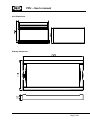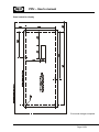
1
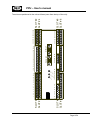
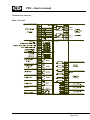
User’s manual
Paralleling and Protection Unit Type PPU
multi-line 2
4189340230E
Software ver. 1.4X
DEIF A/S
• Compact system in one unit
- dynamic synchronisation
- load sharing
- generator protection
• 3-phase ACRMS measurements
•
•
•
•
Calculation of complex AC values
DIN-rail unit with separate display
Easy operator programming via display or PC
Reliable self-monitoring system
DEIF A/S
Tel.:
(+45) 9614 9614
Frisenborgvej 33, DK-7800 Skive Fax:
(+45) 9614 9615
Denmark
E-mail: [email protected]
PPU – User’s manual
This document is the user’s manual for the standard Deif Multi-line 2 PPU.
INDEX:
WARNINGS AND LEGAL INFORMATION ...................................................................................... 5
STANDARD FUNCTIONS ................................................................................................................. 5
LANGUAGE ...................................................................................................................................... 5
CONTROL FUNCTIONS ...................................................................................................................... 5
GENERATOR PROTECTION FUNCTIONS ............................................................................................. 6
OPTIONS............................................................................................................................................ 6
HARDWARE ...................................................................................................................................... 7
TERMINAL STRIP OVERVIEW ........................................................................................................ 9
SLOTS 1,2,5 AND 6.......................................................................................................................... 9
SLOTS 3,4 AND 8........................................................................................................................... 10
TERMINAL STRIP, EXPLANATION............................................................................................... 11
SLOT #1, POWER SUPPLY AND BINARY I/O..................................................................................... 11
Inputs ...................................................................................................................................... 12
Alarm relays............................................................................................................................ 13
Status relay, slot #1................................................................................................................ 13
kWh and kvarh counter .......................................................................................................... 13
SLOT #2, SERIAL COMMUNICATION (OPTION H) ............................................................................. 14
CAN-open (Option H1):.......................................................................................................... 14
MOD-bus (Option H2): ........................................................................................................... 14
SLOT #3, LOAD SHARING CONTROL ................................................................................................ 15
Deload input ........................................................................................................................... 16
SLOT #4, A NALOG SPEED GOVERNOR / AVR (OPTION E)............................................................... 18
SLOT #5, AC MEASURING ............................................................................................................. 19
SLOT #6, ANALOGUE TRANSDUCER OUTPUT (OPTION F1)/(SLOT #4 (OPTION F2)).......................... 20
SLOT #8, AVR VOLTAGE CONTROL RELAY OUTPUTS (OPTION D) ................................................... 20
WIRINGS .......................................................................................................................................... 21
AC CONNECTIONS ......................................................................................................................... 21
LOAD SHARING LINES..................................................................................................................... 22
BINARY INPUTS .............................................................................................................................. 22
ANALOGUE INPUTS (EXTERNAL SET- POINTS) .................................................................................. 23
0…10 VDC input using potentiometer:.................................................................................. 23
+/- 10 V input using potentiometer: ....................................................................................... 23
OPTOCOUPLER OUTPUTS FOR EXTERNAL COUNTER ....................................................................... 24
DISPLAY I/F CABLE (OPTION J) ...................................................................................................... 24
PC I/F CABLE (OPTION J3) ............................................................................................................ 25
DISPLAY UNIT................................................................................................................................. 25
PUSH-BUTTON FUNCTIONS ............................................................................................................ 26
4189340230E
Page 2/54
PPU – User’s manual
DISPLAY FUNCTIONS ...................................................................................................................... 27
First line in display (daily use display functions) ................................................................... 27
Second line in display (daily use display).............................................................................. 27
Second line in display (menu system)................................................................................... 28
Second line in display (alarm and event list)......................................................................... 28
Third line in display (daily use display).................................................................................. 28
Third line in display (parameter menu display) ..................................................................... 28
Fourth line in display (daily use display) ............................................................................... 28
Fourth line in display (parameter menu display) ................................................................... 28
MENU OVERVIEW .......................................................................................................................... 29
PASSWORD SETTING ..................................................................................................................... 30
SERVICE MENU .............................................................................................................................. 30
NAVIGATING IN THE MENUS ............................................................................................................ 31
Setup menu system ............................................................................................................... 31
MENU SET-POINTS ........................................................................................................................ 32
PROTECTION SETUP ...................................................................................................................... 32
Mains/BUS voltage protection option A or B ......................................................................... 32
Mains/BUS frequency protection option A or B..................................................................... 33
Generator voltage protection options A or B ......................................................................... 34
Generator frequency protection options A and B.................................................................. 35
Generator reverse power protection (standard function)...................................................... 36
Generator overcurrent protection (standard function) .......................................................... 36
Generator overload protection option C ................................................................................ 36
Generator current unbalance protection option C................................................................. 37
Generator voltage unbalance protection option C ................................................................ 37
Generator reactive power import (loss of excitation) protection option C............................ 37
Generator reactive power export (overexcitation) protection option C................................. 38
Loss of mains protection option A ......................................................................................... 38
CONTROL SETUP ........................................................................................................................... 39
Synchronisation...................................................................................................................... 39
Blackout closing of breaker.................................................................................................... 39
General failure (sync. fail) ...................................................................................................... 39
PI controller ............................................................................................................................ 40
Deadband (+/- value) ........................................................................................................ 41
Gain factor ......................................................................................................................... 41
ON-time ............................................................................................................................. 41
Diagrams: Analogue output and output activation time ................................................... 41
Frequency controller .............................................................................................................. 42
Power controller ..................................................................................................................... 42
Power ramp up ....................................................................................................................... 42
Power ramp down .................................................................................................................. 43
Power / frequency control mix factor ..................................................................................... 43
Voltage controller option D .................................................................................................... 43
var controller option D ............................................................................................................ 44
var / voltage control mix factor............................................................................................... 44
Power Factor (PF) controller option D................................................................................... 44
POWER SETUP............................................................................................................................... 45
Load dependent start/stop of next generator option G ......................................................... 45
SYSTEM SETUP.............................................................................................................................. 45
4189340230E
Page 3/54
PPU – User’s manual
Nominal settings..................................................................................................................... 45
Transformer ............................................................................................................................ 46
Controller settings .................................................................................................................. 46
Communication control enable / disable control (option H) .................................................. 46
External communication control (option H) ........................................................................... 47
External communication control (option H) ........................................................................... 47
Date and time (internal clock) setting .................................................................................... 47
Auto detection of running signal ............................................................................................ 47
Battery undervoltage alarm.................................................................................................... 48
Language................................................................................................................................ 48
ANALOGUE OUTPUT OPTION F1/F2 ................................................................................................ 48
Power (P kW) output .............................................................................................................. 48
Apparent Power (S kVA) output ............................................................................................ 49
Reactive Power (Q kvar) output ............................................................................................ 49
Power factor (PF) output........................................................................................................ 49
Frequency output ................................................................................................................... 49
Voltage output ........................................................................................................................ 50
Current output ........................................................................................................................ 50
USER PASSWORD .......................................................................................................................... 50
SERVICE MENU .............................................................................................................................. 50
GENERAL DATA............................................................................................................................. 51
TECHNICAL SPECIFICATIONS .......................................................................................................... 51
UNIT DIMENSIONS ......................................................................................................................... 53
DISPLAY DIMENSIONS .................................................................................................................... 53
PANEL CUTOUT FOR DISPLAY ......................................................................................................... 54
4189340230E
Page 4/54
PPU – User’s manual
Warnings and legal information
This manual gives guidelines to installation of the DEIF Multi-line 2 generator control and
protection units. It is, however, not a complete installation instruction. Therefore, even if terminal
numbers are shown in the drawings, the drawings are to be used as guidance only.
Installing and operating the Multi-line 2 products implies work with dangerous currents and voltages,
and therefore it should be done by qualified personnel only.
Care must be taken during installation to protect the terminals against static discharges. Once the
unit is installed and connected, these precautions are no longer necessary.
DEIF takes no responsibility for operation or installation of the generator set. If there is any doubt
about how to install or operate the system on which the Multi-line 2 products are measuring, the
company responsible for installation or operation must be contacted.
Standard functions
The PPU is a control and protection unit for a generator driven by a diesel / gas engine or a
turbine. The PPU will carry out all necessary tasks to control and protect a generator, regardless
of the use of the generator. This means that the PPU can be used for several application types
such as:
Stand-alone generator
Multiple generator load sharing control
Fixed load to mains / base load
The PPU measuring system is true RMS 3-phase measurement of generator voltage, generator
current and BUS (mains) voltage.
Language
English, German, French or Spanish language may be chosen via the system menu structure.
Control functions
-
-
Dynamic synchronisation
o Frequency matching
o Voltage check
o Breaker delay time compensation
o Check phase sequence
Fixed load (base load) running of the generator
Fixed frequency running of a stand-alone generator
Load sharing between generators with power and frequency control
Relay outputs for speed governor and AVR
Relay outputs to close / open generator breaker
Adjustable ramp up/down of generator load
4189340230E
Page 5/54
PPU – User’s manual
Generator protection functions
-
Reverse power
Over current (2 levels)
Protective functions can be selected to activate one of 4 configurable relays.
Options
Option A and option B cannot be chosen at the same time as some functions are common for
both.
Option
A
A1
A2
A3
B
B1
C
C1
D
D1
D2
E
E1
F
F1
F2
1
Description
Loss of mains protection package
- Over- and under voltage (generator and busbar)
- Over- and under frequency (generator and busbar)
- Vector jump
- Df/dt (ROCOF)
- Over- and under voltage (generator and busbar)
- Over- and under frequency (generator and busbar)
- Df/dt (ROCOF)
- Over- and under voltage (generator and busbar)
- Over- and under frequency (generator and busbar)
- Vector jump
Busbar and generator protection package
- Over- and under voltage (generator and busbar)
- Over- and under frequency (generator and busbar)
Generator add-on protection package
- Overload
- Current unbalance
- Voltage asymmetry
- Reactive power (import (excitation loss)/export)
Voltage/var/cos ö control
Selectable (via binary inputs or (optional) serial
interface) functions:
- Constant voltage (stand-alone)
- Constant reactive power (parallel with mains)
- Constant power factor (parallel with mains)
- Reactive power sharing (parallel with other generators,
island operation)
- Constant voltage (stand-alone/synchronisation)
Analogue controller outputs
- +/-20mA for speed governor
- +/-20mA for voltage/var/cos ö control (option D)
Analogue transducer output
- 2 x analogue transducer output
- +/-20mA for selectable AC values
- 4 x analogue transducer output
- +/-20mA for selectable AC values
Not possible if option F2 is selected.
2
Available for
GPC
PPU
Available
GPU
Now
X
X
X
Aug. 2001
X
X
X
Aug. 2001
X
X
X
Now
X
X
X
Now
X
X
Now
X
X
Aug. 2001
X
X
Now
X
X
X
X
X
X
2
Now
Now
1
X
Not possible if option E is selected.
4189340230E
Page 6/54
1
2
X
PPU – User’s manual
Option
G
G1
H
H1
H2
H3
J
J1
J2
J3
K
L
Z
Description
Start/stop relay outputs
- 2 x relay output for start and stop of other generators,
programmable set points and timers
Serial communication
- CAN-open
- Mod-bus
- Profi-bus
Cables
- Display cable with plugs, 3m. UL94 (V1) approved
- Display cable with plugs, 6m. UL94 (V1) approved
- Serial cable for utility SW com., 3m. UL94 (V1) approv.
User’s manual (hard copy)
- The manual is enclosed on a CD-Rom
Display gasket for IP54
Nominal power > 20MW (free of charge)
Available for
GPC
PPU
Available
GPU
Now
X
Standard
X
June 2001
Now
Aug. 2001
X
X
X
X
X
X
X
X
X
Now
Now
Now
X
X
X
X
X
X
X
X
X
X
X
X
Now
Now
X
X
X
X
X
X
Hardware
The PPU unit housing is divided into board slot positions, some of which are standard (nonchangeable) and some intended for options. The unit is divided like this:
Slot #1: Standard
Slot #2:
Slot #3: Standard
Slot #4:
Slot #5: Standard
Slot #6:
Slot #7: Not used
Slot #8:
Terminal 1-28
Terminal 29-36
Terminal 37-64
Terminal 65-72
Terminal 73-89
Terminal 90-97
Terminal 98-125
Terminal 126-133
In the standard PPU, the only slots used are as standard slots #1, #3 and #5. Slots #2, #4, #6
and #8 are used for options, slot #7 is not used.
Besides the slots, there is an additional board where the communication ports are placed. I.e.
RS232 PC service port for the utility software and the display port.
NOTE:
For slots #1, #3 and #5 only specific boards can be mounted.
For slots #2, #4, #6 and #8 the boards are interchangeable.
An overview of the terminals can be seen on the next page.
4189340230E
Page 7/54
SLOT #5
SLOT #7
3
4
5
6
7
8
9 10 11 12 13 14
98
112 113 114 115 116 117 118 119 120 121 122 123 124 125
85 86 87 88 89
DISPLAY
126 127 128 129 130 131 132 133
90 91 92 93 94 95 96 97
65 66 67 68 69 70 71 72
51 52 53 54 55 56 57 58 59 60 61 62 63 64
Service port
29 30 31 32 33 34 35 36
15 16 17 18 19 20 21 22 23 24 25 26 27 28
79 80 81 82 83 84
99 100 101 102 103 104 105 106 107 108 109 110 111
73 74 75 76 77 78
Po
we
r
Se
lf c
he
ck
ok
37 38 39 40 41 42 43 44 45 46 47 48 49 50
2
inh
ibit
Ala
rm
SLOT #1
SLOT #3
1
SLOT #6
SLOT #8
SLOT #2
SLOT #4
PPU – User’s manual
The slots are positioned in the unit as follows (seen from the top of the unit):
4189340230E
Page 8/54
PPU – User’s manual
Terminal strip overview
Slots 1,2,5 and 6
4189340230E
Page 9/54
PPU – User’s manual
Slots 3,4 and 8
4189340230E
Page 10/54
PPU – User’s manual
Terminal strip, explanation
For the relay outputs, following terms will be used:
NO means Normally Open
NC means Normally Closed
Com. means common terminal for the relay in question
Slot #1, power supply and binary I/O
Standard board (always needed):
Term
Function
1
+24 VDC
2
0 VDC
3
NC
4
Com
5
NO
6
Com.
7
NC
8
NO
9
Com.
10
NC
11
NO
12
Com.
13
NC
14
NO
15
Com.
16
NC
17
NO
18
Com.
19
NC
20
Open collector 1
21
Open collector 2
22
Com.
Technical data
24 VDC +20 / - 30 %
Description
Power supply.
Status relay
24V / 1A
Relay 1,
250 VAC / 8A
Normally closed relay, processor
/power supply status supervision
Configurable
Relay 2,
250 VAC / 8A
Configurable
Relay 3,
250 VAC / 8A
Configurable
Relay 4,
250 VAC / 8A
Open breaker (De-load)
Can be configured for tripping
also.
Close breaker (synchronising)
Relay 5,
250 VAC / 8A
Transistor out
Transistor out
Common
23
24
25
26
27
Digital input 1
Digital input 2
Digital input 3
Digital input 4
Digital input 5
Optocoupler
Optocoupler
Optocoupler
Optocoupler
Optocoupler
28
Com
Common
Pulse output 1, kWh counter
Pulse output 2, kvarh counter
Common terminal for terminals
21 and 22
Remote alarm inhibit
Remote alarm acknowledge
Start sync. / control functions
Bus communication control
Block loss of mains (Vector
jump and df/dt (ROCOF) only)
(option A)
Common for terminals 24 to 27
4189340230E
Page 11/54
PPU – User’s manual
Inputs
The inputs 23-27 on slot #1 are control inputs. Terminal 28 is the common.
Input 23:
The frequency and voltage alarms can be inhibited according to the table.
Breaker
Inhibit
Generator low f/U
Generator high f/U
Bus low f/U
Bus high f/U
OFF
ON
ACT
-
ON
OFF
ACT
ACT
-
ON
ACT
-
OFF
ACT
ACT
ACT
ACT
ACT = Alarm active.
All other alarms are not depending on the breaker status.
The alarm inhibit LED on the display is lit when this input is set.
To avoid the use of the inhibit input the auto detection of running signal can be used. The
channel number is 4110. The auto detection of running signal inhibits generator low frequency
and low voltage alarms when the measurements are below 30% of the nominal values.
Input 24:
All the alarms are acknowledged when this input is activated. This is used for acknowledging
alarms by a PLC or by relay logic. All alarms are acknowledged by this input.
Input 25:
This is the start sync. input. When this is set, the “regulator on” LED on the display is lit, and the
multi-line 2 is controlling the speed governor/AVR.
This input must be removed if e.g. an alarm condition activates relay 4 (breaker opening) and the
regulation must stop. Otherwise the multi-line 2 will synchronise the generator to the bus bar
again. When this input is ON, the selected running modes are active. If the input terminal 25 is
OFF, all control functions are disabled and the running situation is frozen. This includes terminal
43, deloading.
If input 25 and the deload input 43 are set, the generator is running at the nominal frequency.
Input 26:
This input is used when external communication e.g. MOD-bus is used. Refer to the bus
protocols.
Input 27:
The block loss of mains input is inhibiting the loss of mains protection. This is normally set if
closing of generator breakers causes fluctuations and is normally set a few seconds. To indicate
that input 27 is set, the alarm inhibit LED on the display is flashing.
4189340230E
Page 12/54
PPU – User’s manual
Alarm relays
5 relays are mounted in the power supply and binary I/O board in slot #1. Of these 5 relays one is
used for closing of the generator breaker (relay 5), and one is used for opening of the generator
breaker (relay 4).
The relays 1-4 can be configured as alarm relays. This is done in the protection menu, in the
control menu and in the system menu. Each alarm can be configured to two outputs, output A
and output B.
If the alarm function is enabled, an alarm will always be displayed on the multi-line 2. Further you
can activate a relay which can be used to control your application. The relay can e.g. be used for
alarm systems, dropping of unimportant load or as inputs to a PLC.
Since each alarm can be configured to two relays, you can combine the use, e.g. output A to an
alarm panel and output B to drop unimportant load.
The PPU is controlling the speed governor output and AVR output in protection alarm conditions.
This means that if an alarm has been configured to relay 4 (opening of breaker), it will
automatically start synchronising immediately. To avoid this situation, the start/sync. input 25
must be removed.
In general failure conditions (sync. failure) the regulation stops and the running situation is frozen.
Status relay, slot #1
The status relay on the power supply board is a normally closed relay with the purpose of
processor and power supply supervision. This relay cannot be configured to any alarms.
kWh and kvarh counter
The PPU monitors the energy production of each unit and it has pulse-outputs for kWh and
kVARh measurement. The number of pulses depends on the nominal output of the generator as
follows.
Pnom
Pnom
Pnom
< 100 kW
100-1000 kW
> 1000 kW
1 pulse/kW
1 pulse/10 kW
1 pulse/100 kW
The pulse length is 1 s/pulse.
4189340230E
Page 13/54
PPU – User’s manual
Slot #2, Serial communication (option H)
CAN-open (Option H1):
Term.
29
30
31
32
33
34
35
36
Function
CAN-H
GND
CAN-L
CAN-H
GND
CAN-L
Not used
Not used
Description
The CAN is based on CAN-open.
MOD-bus (Option H2):
Term.
29
30
31
32
33
34
35
36
Function
DATA + (A)
GND
DATA - (B)
DATA + (A)
GND
DATA - (B)
Not used
Not used
Description
The serial communication line should be terminated with a resistor equal to the cable impedance.
Use shielded twisted pair cable.
4189340230E
Page 14/54
PPU – User’s manual
Slot #3, load sharing control
Term.
Function
Technical
data
Analogue I/O
Common
Analogue I/O
Analogue
input
Common
Analogue
input
37
38
39
40
-5…0…5 VDC
Com
-5…0…5 VDC
-10…0…10 VDC
41
42
Com
-10…0…10 VDC
43
44
Binary input 6
Binary input 7
Optocoupler
Optocoupler
45
Binary input 8
Optocoupler
46
Binary input 9
Optocoupler
47
Binary input 10
Optocoupler
48
49
50
51
52
53
54
55
56
57
58
59
60
61
62
63
64
Binary input 11
Binary input 12
Binary input 13
Binary input 14
Binary input 15
Binary input 16
Binary input 17
Binary input 18
Com
NO
Com
NO
Com
NO
Com
NO
Com
Optocoupler
Optocoupler
Optocoupler
Optocoupler
Optocoupler
Optocoupler
Optocoupler
Optocoupler
Common
Relay no. 6
250 VAC 8A
Relay no. 7
250 VAC 8A
Relay no. 8
250 VAC 8A
Relay no. 9
250 VAC 8A
Description
Active load sharing line
Common for load sharing lines
Reactive load sharing
Frequency / Active load set-point. Passive
(requires external power supply)
Common for terminals 40 and 42
Voltage /var/Power factor/Reactive load
set-point. Passive (requires external power
supply)
De-load (not possible in freq-control mode)
Manual raise speed (only active when “start
sync. /reg.” is OFF)
Manual lower speed (only active when
“start sync. /reg.” is OFF)
Manual raise voltage (only active when
“start sync. /reg.” is OFF)
Manual lower voltage (only active when
“start sync. /reg.” is OFF)
Mode 1
Mode 2
Mode 3
Mode 4
Mode 5
Mode 6
Generator breaker open
Generator breaker closed
Common for terminals 43 to 55
Engine speed governor: Raise speed
Engine speed governor: Lower speed
Start signal at high generator load = CC
(option G)
Stop signal at low generator load = CC
(option G)
Mode 1-6: These controls are only active when the breaker is closed and the start sync. input is
ON.
Control selections with mode 1-6 inputs: See page 17.
The manual binary inputs can be used when the start/sync. input 25 is not activated. They
respond to both relay and analogue outputs.
4189340230E
Page 15/54
PPU – User’s manual
Deload input
The PPU has a deload function which is used when the generator breaker has to be opened with
no load. The deload function is primarily used when running parallel with generators or the mains.
This function is activated by setting input 43 with a binary signal. Then the deloading is started
depending on the running condition.
When running in stand-alone mode, it is not possible to deload the generator as there is no other
generator to take the load. If the deload input is set, the breaker will be opened instantly in fixed
frequency mode. In base load, droop and loadsharing mode the speed of the generator will be
decreased. The breaker will not open.
When running in parallel, the deload input will still open the breaker instantly in fixed frequency
mode. In base load, droop and loadsharing mode the load will be decreased and the breaker will
open at a configurable set point. The factory setting is 5% of nominal power.
If the deload input is left ON after opening of the breaker, it will prevent resynchronisation.
4189340230E
Page 16/54
PPU – User’s manual
Power / frequency
mode selection
Fixed frequency
Base load (Fixed Power)
Droop
Load sharing
Mode 1
Mode 2
OFF
ON
OFF
ON
OFF
OFF
ON
ON
Power / frequency modes
Internal set-point
External (terminals 40(signal) and 41(gnd))
set-point
External set-point values:
Mode
Input
Fixed frequency
-10…0…+10 VDC
Base load (Fixed Power)
0…10 VDC
Droop
-10…0…+10 VDC
Load sharing
-10…0…+10 VDC
Voltage/var/power
factor mode selection
(option D)
Fixed voltage
Fixed var control
Fixed power factor
control
var sharing
Mode 3 OFF
Mode 3 ON
Value
- 5…0…+5 Hz related to nominal frequency
0…100% load related to nominal power
- 5…0…+5 Hz related to nominal frequency
- 5…0…+ 5Hz related to nominal frequency
Mode 4
Mode 5
OFF
ON
OFF
OFF
OFF
ON
ON
ON
Voltage/var/power factor modes (option D)
Internal set-point
External (terminals 42(signal) and 41(gnd))
set-point
External set-point values:
Mode
Input
Fixed voltage
-10…0…+10 VDC
Fixed var control
0…10 VDC
Fixed power factor
0…+10 VDC
control
var sharing
-10…0…+10 VDC
Mode 6 OFF
Mode 6 ON
Value
- 10…0…+10 % related to nominal voltage
0…100% load related to nominal power
Cos ϕ 1…0.6 inductive
- 10…0…+10 % voltage setting related to
nominal voltage
External set-point inputs are passive and require an external power source (+/- 10 VDC)
4189340230E
Page 17/54
PPU – User’s manual
Slot #4, Analog speed governor / AVR (option E)
These outputs are active outputs i.e. they use the internal power supply. The outputs are
galvanically separated from each other and the rest of the unit.
The current outputs can if needed be converted to voltage using a resistor across the terminals
(250 Ω will convert the +/- 20 mA into +/- 5 VDC).
Term.
65
66
67
68
69
70
71
72
Note 1:
Function
Not used
+/- 20 mA out
0
Not used
Not used
+/- 20 mA out
0
Not used
Description
Speed governor set-point output.
1)
AVR voltage set-point output.
Voltage control set-point to AVR is an option (option D).
If the combination of analogue speed governor signals and relay AVR signals
is needed, the analogue speed governor signal is taken from slot #4, and the
AVR relay outputs are taken from slot #8 relays 10 and 11.
4189340230E
Page 18/54
PPU – User’s manual
Slot #5, AC measuring
Term.
73
74
75
76
77
78
79
80
81
82
83
84
85
86
87
88
89
Note:
Function
I L1 s1
I L1 s2
I L2 s1
I L2 s2
I L3 s1
I L3 s2
U L1
U L2
U L3
U Neutral
U L1
U L2
U L3
Technical description
Generator current L1
Description
1/5 A AC input
Generator current L2
1/5 A AC input
Generator current L3
1/5 A AC input
Generator voltage L1
Not used
Generator voltage L2
Not used
Generator voltage L3
Generator voltage
neutral
BUS voltage L1
Not used
BUS voltage L2
Not used
BUS voltage L3
Max. 690 VAC phase - phase value
Max. 690 VAC phase - phase value
Max. 690 VAC phase - phase value
For land-based applications only
Max. 690 VAC phase - phase value
Max. 690 VAC phase - phase value
Max. 690 VAC phase - phase value
Current inputs are galvanically separated. Max. 0.3 VA per phase.
Voltage measurements are available in 4 levels:
1)
2)
3)
4)
100 to 110 VAC
200 to 240 VAC
380 to 480 VAC
660 to 690 VAC
The voltage level is to be defined when ordering, but can be changed onsite
for the levels 1-3. The voltage level 4 (660-690 VAC) cannot be changed
onsite, but must be defined when ordering.
4189340230E
Page 19/54
PPU – User’s manual
Slot #6, analogue transducer output (option F1)/(slot #4 (option F2))
These outputs are active outputs i.e. they use the internal power supply. The outputs are
galvanically separated from each other and the rest of the unit. The individual output can be
selected (in display or via PC programming software) to represent any AC measuring value and
related values (e.g. power, power factor, frequency, etc….).
For actual selection refer to the channel numbers 4500-4560.
Via software selection, the outputs can be selected to be 0…20 mA or 4…20 mA.
The current output can if needed be converted to voltage using a resistor across the terminals
(250 Ω will convert the 0 - 20 mA into 0 - 5 VDC).
The outputs can, by moving a jumper on the board, be selected to be +/- 20 mA if needed.
Term.
Slot #6
90
91
92
93
94
95
96
97
Function
Not used
0
0(4) - 20 mA out
Not used
Not used
0
0(4) - 20 mA out
Not used
Description
Analogue output, selectable
Analogue output, selectable
Slot #8, AVR voltage control relay outputs (option D)
Term.
Slot #8
126
127
128
129
130
131
132
133
Function
Technical data
Description
NO
Com
NO
Com
Not used
Not used
Not used
Not used
Relay 10
250 VAC, 8A
Relay 11
250 VAC, 8A
Generator AVR: Raise voltage
(Option D only)
Generator AVR: Lower voltage
(Option D only)
4189340230E
Page 20/54
PPU – User’s manual
Wirings
AC connections
BUSBAR
L2
L3
L1
N
PPU
89 UL3
87 UL2
BUSBAR
VOLTAGE
85 UL1
18
BREAKER
ON
19
15
BREAKER
OFF
16
84 N
83 UL3
81 UL2
GENERATOR
VOLTAGE
79 UL1
s2
s1
s2
s1
s2
78
76
I2
75
74
s1
I3
77
73
GENERATOR
CURRENT
I1
GENERATOR
Notes:
The neutral line (N) connection is not necessary for correct measurement. 3phase without neutral is also possible.
The current transformers ground connection can be on s1 or s2 connection,
whichever is preferred.
Fuses: 2A slow-blow.
4189340230E
Page 21/54
PPU – User’s manual
Load sharing lines
Even though screened cable is not needed, it is recommended if the cable run is longer than 5 m
between units.
Binary inputs
All binary inputs are 24 VDC bi-directional optocoupler. Typical input is:
4189340230E
Page 22/54
PPU – User’s manual
Analogue inputs (external set-points)
The set-point inputs are passive, i.e. an external power source is needed. This can be an active
output from e.g. a PLC, or a potentiometer can be used.
0…10 VDC input using potentiometer:
+/- 10 V input using potentiometer:
4189340230E
Page 23/54
PPU – User’s manual
Optocoupler outputs for external counter
The kWh counter (terminals 21-23) and kvarh counter (terminals 21-22) outputs are low-power
outputs. For that reason the following circuit must be applied:
+ 24 VDC
EXTERNAL
COUNTER
0.5 uF
100V
PPU
20(kWh)
22 (COMMON)
O VDC
Display I/F cable (option J)
A standard computer extension cable can be used (9-pole SUB-D male / female plugs) or a cable
can be tailored:
2
Wires min 0.22 mm . The cable length is 3m. (option J1) or 6m. (option J2).
Cable types: Belden 9540, BICC H8146, Brand Rex BE57540 or equivalent.
4189340230E
Page 24/54
PPU – User’s manual
PC I/F cable (option J3)
A standard computer null-modem cable can be used (9-pole SUB-D female / female plugs) or a
cable can be tailored:
The cable length is 3m.
Display unit
The display unit used in multi-line 2 communicates and receives power supply via a 9-pole Sub-D
plug. The plug fits directly onto the main unit, so the display can be mounted on the top of the
main unit.
If the display is to be used as remote display, a standard computer extension cable with male /
female plug can be used for the connection.
Display dimensions HxWxD = 115 x 220 x 20 mm
4189340230E
Page 25/54
PPU – User’s manual
Push-button functions
There are 10 push-buttons on the display unit with the following functions:
INFO:
Shifts the display 3 lower lines to show the alarm list (up to 30 alarms can be in the
list).
JUMP:
Enters a menu number selection. All settings have a specific number attached to it.
Using the JUMP button enables the user to select and display any setting without
navigating all the way through the menus (see later).
VIEW:
Shifts the upper line displaying. The following values can be shown:
3 generator voltages (phase-to-phase)
3 BUS voltages (phase-to-phase)
3 generator currents
Generator power factor and produced power (kW)
Generator apparent power (VA) and reactive power (kvar)
Generator L1 frequency and voltage
BUS L1 frequency and voltage
LOG:
Shifts the display 3 lower lines to show the event and alarm list
:
Moves the cursor left for manoeuvring in the menus.
:
Increases the value of the selected set-point (in the setting menus). In the daily use
display it is used for scrolling the second line displaying of generator values.
SEL:
Is used to select the chosen function (underscored selection in the lower line of the
display).
:
BACK:
:
Decreases the value of the selected set-point (in the setting menus). In the daily use
display it is used for scrolling the second line displaying of generator values.
Jumps backwards one step in the menu (to previous display).
Moves the cursor right for manoeuvring in the menus.
4189340230E
Page 26/54
PPU – User’s manual
Display functions
First line in display (daily use display functions)
The first line is used to display generator and BUS values. Typically the line will show 2 or 3
different values at the same time. The following line values can be seen:
- Generator voltage L1 L2 L3 (VAC)
- BUS voltage L1 L2 L3 (VAC)
- Generator current L1 L2 L3 (A)
- Generator Power Factor and active power (kW)
- Generator apparent power (kVA) and reactive power (kvar)
- Generator L1 frequency (Hz) and voltage (VAC)
- BUS L1 frequency (Hz) and voltage (VAC)
Second line in display (daily use display)
The second line is a service line where various values can be shown. Scrolling is done using the
and
keys. The values available are:
For generator:
voltage L1-N (VAC)
voltage L2-N (VAC)
voltage L3-N (VAC)
voltage L1-L2 (VAC)
voltage L2-L3 (VAC)
voltage L3-L1 (VAC)
voltage max. (VAC)
voltage min. (VAC)
current L1 (A)
current L2 (A)
current L3 (A)
frequency L1 (Hz)
frequency L2 (Hz)
frequency L3 (Hz)
active power (kW)
reactive power (kvar)
apparent power (kVA)
energy counter (kWh)
power factor
voltage angle between L1-L2 (deg.)
voltage angle between L2-L3 (deg.)
voltage angle between L3-L1 (deg.)
For BUS:
voltage L1-N (VAC)
voltage L2-N (VAC)
voltage L3-N (VAC)
voltage L1-L2 (VAC)
voltage L2-L3 (VAC)
voltage L3-L1 (VAC)
voltage max. (VAC)
voltage min. (VAC)
frequency (Hz)
voltage angle between L1-L2 (deg.)
frequency deviation (df/dt) (Hz / sec.)
voltage angle between generator voltage
and BUS voltage (deg.)
power supply voltage (VDC)
4189340230E
Page 27/54
PPU – User’s manual
Second line in display (menu system)
When entering the menu system, the second line in the display is used for information about
which function (with function identifying number) is chosen.
Using the
and
keys will scroll through the settings.
Second line in display (alarm and event list)
When selecting the alarm (and event) list, the second line will display the latest alarm / event.
Using the
and
keys will scroll through the list.
Third line in display (daily use display)
The third line is an indication line. The third line contains an explanation for the lower line
selection of setup.
Third line in display (parameter menu display)
In the parameter menu, the third line indicates the present setting of the function in question, and,
if changes are to be made, the max. and min. possible value for the setting.
Fourth line in display (daily use display)
In the daily use display, the fourth line is the entry selection for the parameter menu. If “SEL” is
pressed, the selection of menu indicated with an underscore will be entered.
Choices are:
“PROT”, protection setup
“CTRL”, controls setup
“POWER”, power control setup
“SYST”, system setup
The settings related to the setup can be seen in the paragraph “Menu overview”, where the
specific function numbers (related to the “JUMP” function) can be seen.
Fourth line in display (parameter menu display)
When entering the parameter menus, the first (entry) display uses the fourth line to select a subfunction for the parameter. What the selections are is dependent on the function selected.
4189340230E
Page 28/54
PPU – User’s manual
Examples:
For protective function, the first entry shows the “BUS high volt 1” setting (provided the option is
chosen). In this case the fourth line shows:
“LIM”, setting of switch point
“DEL”, setting of time delay
“OA” and “OB”, selection of which relay the function must activate.
“ACT”, activate / de-activate the function.
For control functions, the first entry shows the “Synchronisation” function. In this case the fourth
line shows:
“fMax”, max. allowed positive frequency deviation when synchronising.
“fMin”, min allowed negative frequency deviation when synchronising.
“Umax”, max. allowed voltage deviation (positive or negative) when synchronising.
“tCB”, closing time delay for generator circuit breaker.
For power setup, the first entry shows the “Start next gen.” relay output (if the option is chosen).
In this case the fourth line shows:
“LIM”, setting of load dependent start output activation limit.
“DEL”, time delay for activating the relay.
“ACT”, activate / de-activate the function.
Note that no relay selection is present. This is due to the fact that the function relates to a predetermined relay output on slot #3.
For system setup, the first entry shows the “Nominal settings”. In this case the fourth line shows:
“F”, nominal frequency setting.
“P”, nominal generator power setting.
“I”, nominal generator current setting.
“U”, nominal generator voltage setting.
The above settings are used by the PPU to calculate nominal apparent power and current.
Menu overview
The following is the menu structure when entering settings of the PPU. If no entry has taken
place before, the first display to appear is the password display. Enter the factory setting
password to gain access to the menus.
If no actions have been taken within 3 minutes, the password entry will be de-activated, and a
new password entry will be needed.
The menu overview is divided according to the daily use display selections in the fourth line
(“PROT”, “CTRL”, “POWER”, “SYST”.)
4189340230E
Page 29/54
PPU – User’s manual
Password setting
The password setting falls outside the menu structure and can only be entered via the “JUMP”
push-button.
Select no. 4976 to enter password setting and select your own password. Use the
and the
buttons to change the setting and the “SEL” button to store the new setting. Beware: Write
down the new password. If you forget it, entering the menus will not be possible.
Service menu
The service menu falls outside the menu structure and can only be entered via the “JUMP” pushbutton. Select channel 4980 to enter the service menu.
4189340230E
Page 30/54
PPU – User’s manual
Navigating in the menus
The menu navigating starts from the daily use display fourth line and is carried out from there
using the “SEL”,
,
,
,
and “BACK” push-buttons.
Setup menu system
The following is an example, but all menus operate in the same manner.
Starting from the daily use display fourth line, select the menu indicated with underscore:
(move the underscore with the
and
pushbuttons)
PROT CTRL POWER SYST
BACK
SEL
1010 BUS high-volt 1
Set point
103.0 %
1020 BUS high-volt 2
Set point
105.0 %
LIM DEL OA OB ACT
LIM DEL OA OB ACT
….ETC.
BACK
SEL
First
entry?
Yes
No
Enter passw.
1999
increase no.
ENTER
1011 BUS high-volt 1
100.0 103.0 120.0 %
RESET
SAVE
decrease no.
increase setting
decrease setting
and
moves the selection (underscore)
4189340230E
Page 31/54
PPU – User’s manual
Menu set-points
The following lists are in numerical order, i.e. the set-points and timers appear according to the
given number.
Protection setup
Mains/BUS voltage protection option A or B
Voltage selections relate to nominal phase – to phase voltage
No.
Setting
Min.
setting
1010 BUS overvolt 1
Selection display
1011 BUS overvolt 1
Set-point
100.0%
1012 BUS overvolt 1
Time
0.1 s
1013 BUS overvolt 1
Relay output A
R0 (None)
1014 BUS overvolt 1
Relay output B
R0 (None)
1015 BUS overvolt 1
Enable
OFF
No.
1020
1021
1022
1023
1024
1025
Setting
BUS overvolt 2
BUS overvolt 2
BUS overvolt 2
BUS overvolt 2
BUS overvolt 2
BUS overvolt 2
No.
1030
1031
1032
1033
1034
1035
No.
1040
1041
1042
1043
1044
1045
Max. setting
Selection display
Set-point
Time
Relay output A
Relay output B
Enable
Max. setting
Selection display
Set-point
Time
Relay output A
Relay output B
Enable
Min.
setting
80.0%
0.1 s
R0 (None)
R0 (None)
OFF
Max. setting
Selection display
Set-point
Time
Relay output A
Relay output B
Enable
Min.
setting
80.0%
0.0 s
R0 (None)
R0 (None)
OFF
Setting
BUS undervolt 2
BUS undervolt 2
BUS undervolt 2
BUS undervolt 2
BUS undervolt 2
BUS undervolt 2
120.0%
100.0 s
R4 (relay 4)
R4 (relay 4)
ON
Min.
setting
100.0%
0.0 s
R0 (None)
R0 (None)
OFF
Setting
BUS undervolt 1
BUS undervolt 1
BUS undervolt 1
BUS undervolt 1
BUS undervolt 1
BUS undervolt 1
Max. setting
120.0%
100.0 s
R4 (relay 4)
R4 (relay 4)
ON
100.0%
100.0 s
R4 (relay 4)
R4 (relay 4)
ON
100.0%
100.0 s
R4 (relay 4)
R4 (relay 4)
ON
Factory
setting
103.0%
10.0 s
R2 (relay 2)
R0 (None)
OFF
Factory
setting
105.0%
5.0 s
R1 (relay 1)
R0 (None)
OFF
Factory
setting
97.0%
10.0 s
R2 (relay 2)
R0 (None)
OFF
Factory
setting
95.0%
5.0 s
R1 (relay 1)
R0 (None)
OFF
4189340230E
Page 32/54
PPU – User’s manual
Mains/BUS frequency protection option A or B
Frequency settings relate to nominal frequency setting.
No.
Setting
1050
1051
1052
1053
1054
1055
BUS high freq. 1
BUS high freq. 1
BUS high freq. 1
BUS high freq. 1
BUS high freq. 1
BUS high freq. 1
No.
1060
1061
1062
1063
1064
1065
BUS high freq. 2
BUS high freq. 2
BUS high freq. 2
BUS high freq. 2
BUS high freq. 2
BUS high freq. 2
Max. setting
Selection display
Set-point
Time
Relay output A
Relay output B
Enable
Min.
setting
90.0%
0.1 s
R0 (None)
R0 (None)
OFF
Max. setting
Selection display
Set-point
Time
Relay output A
Relay output B
Enable
Min.
setting
90.0%
0.0 s
R0 (None)
R0 (None)
OFF
Setting
BUS low freq. 1
BUS low freq. 1
BUS low freq. 1
BUS low freq. 1
BUS low freq. 1
BUS low freq. 1
No.
1080
1081
1082
1083
1084
1085
Max. setting
Selection display
Set-point
Time
Relay output A
Relay output B
Enable
Min.
setting
100.0%
0.0 s
R0 (None)
R0 (None)
OFF
Setting
No.
1070
1071
1072
1073
1074
1075
Max. setting
Selection display
Set-point
Time
Relay output A
Relay output B
Enable
Min.
setting
100.0%
0.1 s
R0 (None)
R0 (None)
OFF
Setting
BUS low freq. 2
BUS low freq. 2
BUS low freq. 2
BUS low freq. 2
BUS low freq. 2
BUS low freq. 2
110.0%
100.0 s
R4 (relay 4)
R4 (relay 4)
ON
110.0%
100.0 s
R4 (relay 4)
R4 (relay 4)
ON
100.0%
100.0 s
R4 (relay 4)
R4 (relay 4)
ON
100.0%
100.0 s
R4 (relay 4)
R4 (relay 4)
ON
Factory
setting
103.0%
10.0 s
R2 relay 2
R0 (None)
OFF
Factory
setting
105.0%
5.0 s
R1 (relay 1)
R0 (None)
OFF
Factory
setting
97.0%
10.0 s
R2 (relay 2)
R0 (None)
OFF
Factory
setting
95.0%
5.0 s
R1 (relay 1)
R0 (None)
OFF
4189340230E
Page 33/54
PPU – User’s manual
Generator voltage protection options A or B
No.
1310
1311
1312
1313
1314
1315
Setting
Gen. high volt 1
Gen. high volt 1
Gen. high volt 1
Gen. high volt 1
Gen. high volt 1
Gen. high volt 1
No.
1320
1321
1322
1323
1324
1325
Gen. high volt 2
Gen. high volt 2
Gen. high volt 2
Gen. high volt 2
Gen. high volt 2
Gen. high volt 2
Max. setting
Selection display
Set-point
Delay
Relay output A
Relay output B
Enable
Min.
setting
80.0%
0.1 s
R0 (None)
R0 (None)
OFF
Max. setting
Selection display
Set-point
Delay
Relay output A
Relay output B
Enable
Min.
setting
80.0%
0.1 s
R0 (None)
R0 (None)
OFF
Setting
Gen. low volt 1
Gen. low volt 1
Gen. low volt 1
Gen. low volt 1
Gen. low volt 1
Gen. low volt 1
No.
1340
1341
1342
1343
1344
1345
Max. setting
Selection display
Set-point
Delay
Relay output A
Relay output B
Enable
Min.
setting
100.0%
0.1 s
R0 (None)
R0 (None)
OFF
Setting
No.
1330
1331
1332
1333
1334
1335
Max. setting
Selection display
Set-point
Delay
Relay output A
Relay output B
Enable
Min.
setting
100.0%
0.1 s
R0 (None)
R0 (None)
OFF
Setting
Gen. low volt 2
Gen. low volt 2
Gen. low volt 2
Gen. low volt 2
Gen. low volt 2
Gen. low volt 2
120.0%
100.0 s
R4 (relay 4)
R4 (relay 4)
ON
120.0%
100.0 s
R4 (relay 4)
R4 (relay 4)
ON
100.0%
100.0 s
R4 (relay 4)
R4 (relay 4)
ON
100.0%
100.0 s
R4 (relay 4)
R4 (relay 4)
ON
Factory
setting
103.0%
10.0 s
R2 (relay 2)
R0 (None)
OFF
Factory
setting
105.0%
5.0 s
R1 (relay 1)
R0 (None)
OFF
Factory
setting
97.0%
10.0 s
R2 (relay 2)
R0 (None)
OFF
Factory
setting
95.0%
5.0 s
R1 (relay 1)
R0 (None)
OFF
4189340230E
Page 34/54
PPU – User’s manual
Generator frequency protection options A and B
No.
1350
1351
1352
1353
1354
1355
Setting
Gen. high freq. 1
Gen. high freq. 1
Gen. high freq. 1
Gen. high freq. 1
Gen. high freq. 1
Gen. high freq. 1
No.
1360
1361
1362
1363
1364
1365
Gen. high freq. 2
Gen. high freq. 2
Gen. high freq. 2
Gen. high freq. 2
Gen. high freq. 2
Gen. high freq. 2
Max. setting
Selection display
Set-point
Delay
Relay output A
Relay output B
Enable
Min.
setting
90.0%
0.2 s
R0 (None)
R0 (None)
OFF
Max. setting
Selection display
Set-point
Delay
Relay output A
Relay output B
Enable
Min.
setting
90.0%
0.2 s
R0 (None)
R0 (None)
OFF
Setting
Gen. low freq. 1
Gen. low freq. 1
Gen. low freq. 1
Gen. low freq. 1
Gen. low freq. 1
Gen. low freq. 1
No.
1380
1381
1382
1383
1384
1385
Max. setting
Selection display
Set-point
Delay
Relay output A
Relay output B
Enable
Min.
setting
100.0%
0.2 s
R0 (None)
R0 (None)
OFF
Setting
No.
1370
1371
1372
1373
1374
1375
Max. setting
Selection display
Set-point
Delay
Relay output A
Relay output B
Enable
Min.
setting
100.0%
0.2 s
R0 (None)
R0 (None)
OFF
Setting
Gen. low freq. 2
Gen. low freq. 2
Gen. low freq. 2
Gen. low freq. 2
Gen. low freq. 2
Gen. low freq. 2
110.0%
100.0 s
R4 (relay 4)
R4 (relay 4)
ON
110.0%
100.0 s
R4 (relay 4)
R4 (relay 4)
ON
100.0%
100.0 s
R4 (relay 4)
R4 (relay 4)
ON
100.0%
100.0 s
R4 (relay 4)
R4 (relay 4)
ON
Factory
setting
103.0%
10.0 s
R2 (relay 2)
R0 (None)
OFF
Factory
setting
105.0%
5.0 s
R1 (relay 1)
R0 (None)
OFF
Factory
setting
97.0%
10.0 s
R2 (relay 2)
R0 (None)
OFF
Factory
setting
95.0%
5.0 s
R1 (relay 1)
R0 (None)
OFF
4189340230E
Page 35/54
PPU – User’s manual
Generator reverse power protection (standard function)
Reverse power settings relate to nominal power setting.
No.
Setting
1090
1091
1092
1093
1094
1095
Reverse power
Reverse power
Reverse power
Reverse power
Reverse power
Reverse power
Min.
setting
-50.0%
0.1 s
R0 (None)
R0 (None)
OFF
Max. setting
Max. setting
Selection display
Set-point
Time
Relay output A
Relay output B
Enable
Min.
setting
50.0%
0.1 s
R0 (None)
R0 (None)
OFF
Max. setting
Selection display
Set-point
Time
Relay output A
Relay output B
Enable
Min.
setting
50.0%
0.1 s
R0 (None)
R0 (None)
OFF
Min.
setting
10.0%
0.1 s
R0 (None)
R0 (None)
OFF
Max. setting
Selection display
Set-point
Time
Relay output A
Relay output B
Enable
0.0%
100.0 s
R4 (relay 4)
R4 (relay 4)
ON
Factory
setting
-5.0%
10.0 s
R1 (relay 1)
R0 (None)
ON
Generator overcurrent protection (standard function)
Settings relate to nominal generator current.
No.
Setting
1100
1101
1102
1103
1104
1105
Overcurrent 1
Overcurrent 1
Overcurrent 1
Overcurrent 1
Overcurrent 1
Overcurrent 1
No.
1110
1111
1112
1113
1114
1115
Setting
Overcurrent 2
Overcurrent 2
Overcurrent 2
Overcurrent 2
Overcurrent 2
Overcurrent 2
200.0%
100.0 s
R4 (relay 4)
R4 (relay 4)
ON
200.0%
100.0 s
R4 (relay 4)
R4 (relay 4)
ON
Factory
setting
115.0%
10.0 s
R2 (relay 2)
R0 (None)
ON
Factory
setting
120.0%
5.0 s
R1 (relay 1)
R0 (None)
ON
Generator overload protection option C
Settings relate to nominal power setting.
No.
Setting
1160
1161
1162
1163
1164
1165
Overload 1
Overload 1
Overload 1
Overload 1
Overload 1
Overload 1
Selection display
Set-point
Time
Relay output A
Relay output B
Enable
200.0%
100.0 s
R4 (relay 4)
R4 (relay 4)
ON
Factory
setting
100.0%
10.0 s
R2 (relay 2)
R0 (None)
OFF
4189340230E
Page 36/54
PPU – User’s manual
No.
1170
1171
1172
1173
1174
1175
Setting
Overload 2
Overload 2
Overload 2
Overload 2
Overload 2
Overload 2
Selection display
Set-point
Time
Relay output A
Relay output B
Enable
Min.
setting
10.0%
0.1 s
R0 (None)
R0 (None)
OFF
Max. setting
Min.
setting
0.0%
0.1 s
R0 (None)
R0 (None)
OFF
Max. setting
Min.
setting
0.0%
0.1 s
R0 (None)
R0 (None)
OFF
Max. setting
200.0%
100.0 s
R4 (relay 4)
R4 (relay 4)
ON
Factory
setting
110.0%
5.0 s
R1 (relay 1)
R0 (None)
OFF
Generator current unbalance protection option C
Settings relate to nominal generator current.
No.
Setting
1220
1221
1222
1223
1224
1225
Current unbalance
Current unbalance
Current unbalance
Current unbalance
Current unbalance
Current unbalance
Selection display
Set-point
Time
Relay output A
Relay output B
Enable
100.0%
100.0 s
R4 (relay 4)
R4 (relay 4)
ON
Factory
setting
30.0%
10.0 s
R2 (relay 2)
R0 (None)
OFF
Generator voltage unbalance protection option C
Settings relate to nominal generator voltage.
No.
Setting
1230
1231
1232
1233
1234
1235
Voltage unbalance
Voltage unbalance
Voltage unbalance
Voltage unbalance
Voltage unbalance
Voltage unbalance
Selection display
Set-point
Time
Relay output A
Relay output B
Enable
50.0%
100.0 s
R4 (relay 4)
R4 (relay 4)
ON
Factory
setting
10.0%
10.0 s
R2 (relay 2)
R0 (None)
OFF
Generator reactive power import (loss of excitation) protection option C
Settings relate to nominal generator power value (kW).
No.
Setting
1240
1241
1242
1243
1244
1245
var import
var import
var import
var import
var import
var import
Selection display
Set-point
Time
Relay output A
Relay output B
Enable
Min.
setting
0.0%
0.1 s
R0 (None)
R0 (None)
OFF
Max. setting
150.0%
100.0 s
R4 (relay 4)
R4 (relay 4)
ON
Factory
setting
50.0%
10.0 s
R1 (relay 1)
R0 (None)
OFF
4189340230E
Page 37/54
PPU – User’s manual
Generator reactive power export (overexcitation) protection option C
Settings relate to nominal generator power value (kW).
No.
Setting
1250
1251
1252
1253
1254
1255
var export
var export
var export
var export
var export
var export
Selection display
Set-point
Time
Relay output A
Relay output B
Enable
Min.
setting
0.0%
0.1 s
R0 (None)
R0 (None)
OFF
Max. setting
Min.
setting
0.1 Hz/s
1 per
R0 (None)
R0 (None)
OFF
Max. setting
Min.
setting
1.0 deg.
Max. setting
100.0%
100.0 s
R4 (relay 4)
R4 (relay 4)
ON
Factory
setting
60.0%
10.0 s
R2 (relay 2)
R0 (None)
OFF
Loss of mains protection option A
Df/dt (ROCOF) NOTE: Time delay is in periods (per)
No.
Setting
1260
1261
1262
1263
1264
1265
Df/dt (ROCOF)
Df/dt (ROCOF)
Df/dt (ROCOF)
Df/dt (ROCOF)
Df/dt (ROCOF)
Df/dt (ROCOF)
Vector Jump
No.
1270
1271
1272
1273
1274
1275
Vector jump
Vector jump
Vector jump
Vector jump
Vector jump
Vector jump
Selection display
Set-point +/Time
Relay output A
Relay output B
Enable
Setting
Selection display
Set-point
Time
Relay output A
Relay output B
Enable
10.0 Hz/s
20 per
R4 (relay 4)
R4 (relay 4)
ON
Factory
setting
5.0 Hz/s
6 per
R1 (relay 1)
R0 (None)
OFF
Factory
setting
90.0 deg.
10.0 deg.
No delay (immediate trip)
R0 (None)
R4 (relay 4)
R1 (relay 1)
R0 (None)
R4 (relay 4)
R0 (None)
OFF
ON
OFF
The alarm inhibit lamp is flashing if the block loss of mains input is set.
4189340230E
Page 38/54
PPU – User’s manual
Control setup
Synchronisation
The “dU max.” setting is related to nominal generator voltage. The “dU max.” setting is + nominal
generator voltage.
No.
2010
2011
2012
2013
2014
Setting
Synchronisation
Synchronisation
Synchronisation
Synchronisation
Synchronisation
Selection display
Df max.
Df min.
DU max.
Breaker delay
Min.
setting
0.0 Hz
-0.5 Hz
2%
40 ms
Max. setting
0.5 Hz
0.5 Hz
10%
300 ms
Factory
setting
0.3 Hz
0.0 Hz
5%
50 ms
The synchronisation pulse is 400 ms.
Blackout closing of breaker
Settings are the accepted limits (generator voltage and frequency) for closing the breaker. The
“dU max.” setting is related to nominal generator voltage.
No.
2020
2021
2022
2023
Setting
Sync. blackout
Sync. blackout
Sync. blackout
Sync. blackout
Selection display
Df max.
DU max.
Enable
Min.
setting
0.0 Hz
2%
OFF
Max. setting
5.0 Hz
10%
ON
Factory
setting
3.0 Hz
5%
OFF
If blackout closing of breaker is enabled on more units, external precautions must be taken to
avoid two or more generators closing on a black busbar. In that case synchronism will not be
present.
General failure (sync. fail)
The general failure covers:
Synchronisation time
Breaker ON/OFF feedback fail
Generator voltage not established
Generator frequency not established
Phase sequence error
4189340230E
Page 39/54
PPU – User’s manual
No.
2030
2031
2032
2033
Setting
General failure
General failure
General failure
General failure
Selection display
Delay
Relay output A
Relay output B
Min.
setting
0.0 s
R0 (none)
R0 (none)
Max. setting
Factory
setting
60.0 s
R2 (relay 2)
R0 (none)
120.0 s
R4 (relay 4)
R4 (relay 4)
The general failure cannot be disabled.
PI controller
The PPU includes controllers for the different running modes. The controllers control either a
relay output (standard slot #3/option D slot #8) or an analogue output (option E slot #4).
The basic principle of the controller is that a calculation is being executed every 5 * ON time
(relay output) or 5 * integ. time (analogue output). The result of this calculation indicates whether
the actual value (e.g. nominal frequency) is within the deadband. In that case there will be no
changes on the output. If the actual value is differing from the deadband, the controller will cause
an output signal change.
If the relay output is used, the relay will be set for a certain time depending on the deviation from
the actual value to the desired value. The length of the output signal will be up to 5 * ON time.
If the analogue output is used, the analogue signal will change depending on the gain factor and
the deviation from the actual value to the desired value. The period the output signal changes will
be up to 5 * integral time.
After a period of 5 * ON time or 5 * integral time a new calculation is carried out.
From the table below it appears what controllers are active in the different running modes.
Controllers:
Controllers
Freq.
Fixed freq.
Fixed power
Droop
Loadsharing
Fixed voltage
Fixed var
Fixed PF
Loadsharing
Power
Voltage
Mix factor
var
PF
f/P mix
U/var mix
x
x
x
x
x
x
x
x
x
x
x
x
The mix factors are not controllers, but they indicate the influence of the two controllers in
question.
4189340230E
Page 40/54
PPU – User’s manual
Example:
The generator is running in loadshare mode. The f/P mix factor is set to 50%. Now
the frequency controller participates with 50% of the governor control and the power
controller participates with: 100 – 50 = 50%.
When running in the generators, the relevant controller must be set in each desired running
mode. (Fixed frequency mode set frequency controller).
With the exception of the PF controller the controllers are active in more running modes
depending on the application. Regardless of that, the controller values will be the same.
Deadband (+/- value)
The controllers will find a value within the deadband area. If the actual value is within this area
the output signals will not change. When the calculation shows an actual value outside the
deadband area, the output signals change again.
Gain factor
The gain factor indicates with what rate the analogue output signal will change. A higher gain
factor will cause a faster regulation, but it might also cause the prime movers to hunt.
ON-time
The output relay is active for a time of = K * ON time. K is depending on the deviation from
nominal value.
Diagrams: Analogue output and output activation time
f = generator frequency
U = analogue output signal
f = generator frequency
K = konstant
The output signal changes:
t = K x integral time [ms]
4189340230E
Page 41/54
PPU – User’s manual
Frequency controller
The ON / integral time is a combined setting. If relay speed control setting is used, the setting
indicates the shortest relay ON time. If the speed control setting is analogue output (option E),
the setting is for the PI controller integral time.
Frequency % settings relate to nominal generator frequency.
No.
Setting
Min.
setting
2050 Freq. control
Selection display
2051 Freq. control
Droop
0.0%
2052 Freq. control
Dead band
0.2%
2053 Freq. control
Gain
1
2054 Freq. control
ON / Integr. Time
10 ms
Max. setting
10.0%
10.0%
100
3000 ms
Factory
setting
4.0%
1.0%
40
100 ms
Power controller
The ON / integral time is a combined setting. If relay speed control setting is used, the setting
indicates the shortest relay ON time. If the speed control setting is analogue output (option E),
the setting is for the PI controller integral time.
Power % settings relates to nominal generator power.
No.
Setting
2060
2061
2062
2063
Power control
Power control
Power control
Power control
Selection display
Dead band
Gain
ON / Integr. Time
Min.
setting
0.2%
1
10 ms
Max. setting
10.0%
100
3000 ms
Factory
setting
2.0%
40
100 ms
Power ramp up
The delay point and – time is the point where the generator stops ramping after closing of
breaker to pre-heat the engine before commencing to take load. The time duration of the point is
determined by the delay time setting. If the delay function is not needed, set the time to 0.
Power % settings relate to nominal generator power.
No.
Setting
2070
2071
2072
2073
Power ramp up
Power ramp up
Power ramp up
Power ramp up
Selection display
Speed
Delay point
Delay time
Min.
setting
1.0%/s
1.0%
0.0 s
Max. setting
20.0%/s
100.0%
180.0 s
Factory
setting
2.0%/s
10.0%
10.0 s
4189340230E
Page 42/54
PPU – User’s manual
Power ramp down
The breaker open point is where a relay output (relay 4) is activated to open the generator
breaker before reaching 0 kW.
Power % settings relate to nominal generator power.
No.
Setting
2080 Power ramp down
2081 Power ramp down
2082 Power ramp down
Selection display
Speed
Breaker open
Min.
setting
1.0%/s
1.0%
Max. setting
20.0%/s
20.0%
Factory
setting
10.0%/s
5.0%
Power / frequency control mix factor
The mix factor determines the relation between frequency control and power control when
running parallel with other generators (load sharing). The reason for the factor is that there is only
one power / frequency load sharing line.
Setting the factor to 100% selects power control only, setting it to 0% selects frequency control
only.
No.
Setting
2090 P/f contr. mix.
2091 P/f contr. mix.
Selection display
Mix factor
Min.
setting
0.0%
Max. setting
100.0%
Factory
setting
50.0%
Voltage controller option D
The ON / integral time is a combined setting. If relay voltage control setting is used, the setting
indicates the shortest relay ON time. If the voltage control setting is analogue output (option E),
the setting is for the PI controller integral time.
Voltage deadband % settings relate to nominal generator voltage.
No.
Setting
Min.
setting
2100 Voltage control
Selection display
2101 Voltage control
Deadband
0.0%
2102 Voltage control
Gain
1
2103 Voltage control
ON / Integr. time
10 ms
Max. setting
10.0%
100
3000 ms
Factory
setting
2.0%
40
100 ms
4189340230E
Page 43/54
PPU – User’s manual
var controller option D
The ON / integral time is a combined setting. If relay var control setting is used, the setting
indicates the shortest relay ON time. If the var control setting is analogue output (option E), the
setting is for the PI controller integral time.
var deadband % settings relate to nominal generator power value, i.e. it is assumed that the
generator var value is the same as the kW value. This is not correct but the assumption is made
for control purposes only.
No.
2110
2111
2112
2113
Setting
var control
var control
var control
var control
Selection display
Deadband
Gain
ON / Integr. Time
Min.
setting
0.0%
1
10 ms
Max. setting
10.0%
100
3000 ms
Factory
setting
2.0%
40
100 ms
var / voltage control mix factor
The mix factor determines the relation between voltage control and var control when running
parallel with other generators (load sharing). The reason for the factor is that there is only one var
/ voltage load sharing line.
Setting the factor to 100% selects var control only setting it to 0% selects voltage control only.
No.
Setting
2120 var/U contr. mix.
2121 var/U contr. mix.
Selection display
Mix factor
Min.
setting
0.0%
Max. setting
100.0%
Factory
setting
50.0%
Power Factor (PF) controller option D
The ON / integral time is a combined setting. If relay PF control setting is used, the setting
indicates the shortest relay ON time. If the PF control setting is analogue output (option E), the
setting is for the PI controller integral time.
PF deadband is the zone (+/- value) around PF setting value where the relay output does not
operate. The value is disregarded if analogue PF control output is used.
No.
2130
2131
2132
2133
Setting
PF control
PF control
PF control
PF control
Selection display
Deadband
Gain
ON / Integr. Time
Min.
setting
0.00
1
10 ms
Max. setting
0.10
100
3000 ms
Factory
setting
0.05
40
100 ms
4189340230E
Page 44/54
PPU – User’s manual
Power setup
Load dependent start/stop of next generator option G
The relay outputs for start next and stop next are placed in the loadsharing board in slot #3. The
PPU cannot decide what generator to start/stop. This must be handled externally.
Start next generator: Relay 8, terminals 61-62, normally open.
No.
3010
3011
3012
3013
Setting
Start next gen.
Start next gen.
Start next gen.
Start next gen.
Selection display
Start point
Timer
Enable
Min.
setting
0.0%
0.0 s
OFF
Max. setting
150.0%
100.0 s
ON
Factory
setting
80.0%
10.0 s
ON
Stop next generator: Relay 9, terminals 63-64, normally open.
No.
3020
3021
3022
3023
Setting
Stop next gen.
Stop next gen.
Stop next gen.
Stop next gen.
Max. setting
Selection display
Stop point
Timer
Enable
Min.
setting
0.0%
0.0 s
OFF
Max. setting
Selection display
Frequency
Generator Power
Generator current
Generator volt
Min.
setting
48.0 Hz
10 kW
0A
100 V
50.0%
200.0 s
ON
Factory
setting
20.0%
30.0 s
ON
System setup
Nominal settings
No.
4010
4011
4012
4013
4014
Setting
Nominal settings
Nominal settings
Nominal settings
Nominal settings
Nominal settings
62.0 Hz
99 MW
9000 A
25000 V
Factory
setting
60.0 Hz
100 kW
787 A
110 V
4189340230E
Page 45/54
PPU – User’s manual
Transformer
Voltage transformer: If no voltage transformer is present, the primary and secondary side values
are set to generator nominal value.
No.
4020
4021
4022
4023
4024
Setting
Transformer
Transformer
Transformer
Transformer
Transformer
Selection display
Volt prim
Volt sec
Current prim
Current sec
Min.
setting
100 V
100 V
5A
1A
Max. setting
25000 V
690 V
9000 A
5A
Factory
setting
110 V
110 V
1000 A
5A
Controller settings
The setting values are used if external set-point or serial communication set-point is not chosen.
Power setting relates to generator nominal power (kW).
Var setting is inductive reactive power and relates to generator nominal power (kW ~kvar)
Power factor setting is inductive value.
No.
4030
4031
4032
4033
Setting
Controller
Controller
Controller
Controller
Selection display
Power
var
Power factor (ind)
Min.
setting
0.0%
0.0%
0.60
Max. setting
Min.
setting
OFF
OFF
OFF
OFF
OFF
OFF
Max. setting
100.0%
100.0%
1.00
Factory
setting
100.0%
30.0%
0.90
Communication control enable / disable control (option H)
No.
4040
4041
4042
4043
4044
4045
4046
Setting
Comm. control
Comm. control
Comm. control
Comm. control
Comm. control
Comm. control
Comm. control
Selection display
Power
Frequency
Voltage
var
PF
Mode selections
ON
ON
ON
ON
ON
ON
Factory
setting
OFF
OFF
OFF
OFF
OFF
OFF
Note: Selecting Communication control ON will overrule external and internal settings.
4189340230E
Page 46/54
PPU – User’s manual
External communication control (option H)
No.
Setting
4050 External comm.
4051 External comm.
4052 External comm.
Selection display
ID
19200 Baud
Min.
setting
1
OFF
Max. setting
Min.
setting
1.0 s
R0 (None)
R0 (None)
OFF
Max. setting
Min.
setting
-
Max. setting
247
ON
Factory
setting
1
OFF
External communication control (option H)
No.
4090
4091
4092
4093
4094
Setting
External comm. error
External comm. error
External comm. error
External comm. error
External comm. error
Selection display
Delay
Relay output A
Relay output B
Enable
100.0 s
R4 (relay 4)
R4 (relay 4)
ON
Factory
setting
10.0 s
R1 (relay 1)
R0 (None)
OFF
Date and time (internal clock) setting
No.
4100
4101
4102
4103
4104
4105
Setting
Date and time
Date and time
Date and time
Date and time
Date and time
Date and time
Selection display
Year
Month
Date
Hour
Minute
-
Factory
setting
-
These settings have no practical limit.
Factory settings will be present date and
time in Denmark when produced.
Auto detection of running signal
No.
4110 Auto detection run
4111 Auto detection run
Setting
Selection display
Auto det. run
Min.
setting
OFF
Max. setting
ON
Factory
setting
OFF
The voltage and frequency alarms of the generator are inhibited when the measurements are
under 30% of the nominal values.
4189340230E
Page 47/54
PPU – User’s manual
Battery undervoltage alarm
No.
4220
4221
4222
4223
4224
4225
Setting
Battery low V
Battery low V
Battery low V
Battery low V
Battery low V
Battery low V
Selection display
Set-point
Time
Relay output A
Relay output B
Enable
Min.
setting
15.0 V
0.0 s
R0 (None)
R0 (None)
OFF
Max. setting
Setting
Factory
setting
1
1
1
1
24.0 V
10.0 s
R4 (relay 4)
R4 (relay 4)
ON
Factory
setting
18.0 V
1.0 s
R0 (no relay)
R0 (no relay)
ON
Language
No.
Setting
4230 Language
4231 Language
Selection display
English
German
French
Spanish
1
2
3
4
Analogue output option F1/F2
The analogue output options each consist of two independent 0(4)…20 mA outputs. Reconfigured hardware can enable a –20…0…+20 mA output, but this is special.
Each of the two outputs can be chosen to represent any of the following values.
Power (P kW) output
No.
4500
4501
4502
4503
4504
Setting
Power output
Power output
Power output
Power output
Power output
Selection display
Analogue out no.
Type
Max. value
Min. value
Min.
setting
0
0-20 mA
0 kW
-99 MW
Max. setting
2
4-20 mA
99 MW
99 MW
Factory
setting
0
4-20 mA
500 kW
0 kW
4189340230E
Page 48/54
PPU – User’s manual
Apparent Power (S kVA) output
No.
4510
4511
4512
4513
4514
Setting
S output
S output
S output
S output
S output
Max. setting
Selection display
Analogue out no.
Type
Max. value
Min. value
Min.
setting
0
0-20 mA
0 kVA
-99 MVA
Max. setting
Selection display
Analogue out no.
Type
Max. value
Min. value
Min.
setting
0
0-20 mA
0 kvar
-99 Mvar
Max. setting
Selection display
Analogue out no.
Type
Max. value
Min. value
Min.
setting
0
0-20 mA
0.6
-0.6
Max. setting
Selection display
Analogue out no.
Type
Max. value
Min. value
Min.
setting
0
0-20 mA
0 Hz
0 Hz
2
4-20 mA
99 MVA
99 MVA
Factory
setting
0
4-20 mA
600 kVA
0 kVA
Reactive Power (Q kvar) output
No.
4520
4521
4522
4523
4524
Setting
React. power output
React. power output
React. power output
React. power output
React. power output
2
4-20 mA
99 Mvar
99 Mvar
Factory
setting
0
4-20 mA
400 kvar
0 kvar
Power factor (PF) output
No.
4530
4531
4532
4533
4534
Setting
Power factor output
Power factor output
Power factor output
Power factor output
Power factor output
2
4-20 mA
1.0
1.0
Factory
setting
0
4-20 mA
0.8
-0.8
Frequency output
No.
4540
4541
4542
4543
4544
Setting
Frequency output
Frequency output
Frequency output
Frequency output
Frequency output
2
4-20 mA
70 Hz
70 Hz
Factory
setting
0
4-20 mA
55 Hz
45 Hz
4189340230E
Page 49/54
PPU – User’s manual
Voltage output
The voltage output represents the L1-L2 voltage.
No.
Setting
4550
4551
4552
4553
4554
Voltage output
Voltage output
Voltage output
Voltage output
Voltage output
Selection display
Analogue out no.
Type
Max. value
Min. value
Min.
setting
0
0-20 mA
0V
0V
Max. setting
Min.
setting
0
0-20 mA
0A
0A
Max. setting
2
4-20 mA
28000 V
28000 V
Factory
setting
0
4-20 mA
500 V
0V
Current output
The current output represents the L1 current
No.
Setting
4560
4561
4562
4563
4564
Current output
Current output
Current output
Current output
Current output
Selection display
Analogue out no.
Type
Max. value
Min. value
2
4-20 mA
9000 A
9000 A
Factory
setting
0
4-20 mA
1000 A
0A
User password
The user password can only be entered using the “JUMP” push-button.
No.
Setting
4976 User password
Setting
Min.
setting
0
Max. setting
32000
Factory
setting
2000
Service menu
The service menu can only be entered using the “JUMP” push-button.
No.
4980
4981
4982
4983
Setting
Service menu
Service menu
Service menu
Service menu
Description
Selection display
Alarm
Digital input
Digital output
Shows remaining time
Shows input status
Shows output status
4189340230E
Page 50/54
PPU – User’s manual
General data
Technical specifications
Accuracy:
Class 1.0 acc. to IEC 688
Operating temp.:
-25…70 C
Aux. supply:
24 VDC -25 / +30%
Measuring voltage:
100…690 VAC
Frequency:
30…70 Hz
Measuring current:
From current transformers ../1 A or ../5A. Load max. 0.3 VA per phase.
Binary inputs:
Input voltage 12…32 VDC, impedance 2.4 kΩ, bi-directional.
o
Open collector outputs : Supply voltage 12…32 VDC. Load max. 10 mA
Load sharing lines:
+/- 5 VDC
Analog inputs:
+/- 10 VDC, impedance 100 kΩ (not galvanically separated).
Relay outputs:
250V/8A or 24VDC/1A. Refer to actual description of I/O's.
Safety:
To EN 61010-1 Installation category (overvoltage category) III, 600V,
pollution degree 2.
Galvanic separation:
Between AC voltage, AC current and other I/O’s: 3250VAC – 50 Hz –
1 min. Between analogue outputs: 500VDC – 1 min.
EMC / CE:
Acc. to EN-50081-1/2, EN 50082-1/2, SS4361503 (PL4) and IEC 255-3.
Type approval:
DNV, GL, LR and ABS for use in unmanned machinery space.
Material:
All plastic parts are self-extinguishing to UL94 (V1).
Climate:
HSE, to DIN 40040.
Connections:
4 mm multi stranded for AC currents, all others 2.5 mm multi stranded.
Response times:
From the setpoint is reached till the output is activated and the delay set
to 0.
2
Busbar 1:
2
Over/under voltage
Over/under frequency
Generator and busbar 2: Over/under voltage
Over/under frequency
<20 ms
<20 ms
70-150 ms
70-150 ms
4189340230E
Page 51/54
PPU – User’s manual
Response times, cont.:
Current:
Rocof:
Vector jump:
100-160 ms
100 ms (4 periods)
30 ms
Protection:
Case: IP40.
Terminals: IP20.
Operator panel: IP52 (IP54 when mounted with gasket).
To IEC 529 and EN 60529.
Mounting:
Base mounted with six screws or DIN rail mounted.
If DIN rail mounted in marine applications, additional means against
excessive mechanical vibrations must be used.
4189340230E
Page 52/54
PPU – User’s manual
Unit Dimensions
Display dimensions
4189340230E
Page 53/54
PPU – User’s manual
Panel cutout for display
Errors and changes excepted
4189340230E
Page 54/54