1
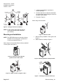
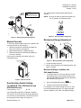
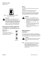
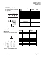
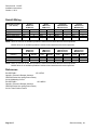
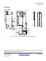
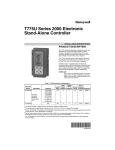
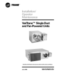
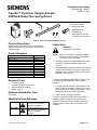
Installation Instructions
Document No. 129-367
October 1, 2013
OpenAir™ Electronic Damper Actuator
GDE/GLB Rotary Non-spring Return
c
e
90
45
EA0678R3
90
f
a
b
d
a.
b.
c.
d.
e.
f.
Actuator
Position indicator
Mounting bracket
Mounting screws
4 mm hex key
Shaft insert for use with
3/8-inch (8-10 mm) shafts
Figure 1. Parts of the GDE/GLB Rotary Actuator.
Product Description
Steps for direct-coupled mounting of the OpenAir
GDE/GLB Series non-spring return rotary electronic
damper actuator.
Product Numbers
GDE131.1U
GDE131.1U/B (24 pk)
GDE131.1P
GDE131.1P/B (24 pk)
GDE131.1Q/B 6-ft cable (12 pk)
GDE132.1P
GDE136.1P
GDE161.1P
GDE161.1P/B (24 pk)
GDE163.1P
GDE164.1P
GDE166.1P
GLB131.1P
GLB132.1P
GLB136.1P
GLB161.1P
GLB163.1P
GLB164.1P
GLB166.1P
Required Tools
•
•
•
•
4 mm hex wrench
4 mm (5/32-inch) drill bit and drill
Small flat-blade screwdriver
Marker or pencil
Estimated Installation Time
WARNING:
Do not open the actuator.
NOTE:
Place the actuator on the damper shaft so
that the front of the actuator is accessible.
The label is on the front side.
1. Determine whether the damper blades will rotate
clockwise or counterclockwise to open. See
Figure 2.
2. If the blades will rotate counterclockwise, slide the
manual override switch to manual, and move the
adjustment lever to the right. Return the switch to
automatic. See Figure 9.
To mount a (modulating) GDE/GLB16x, set the Dual
In-line Package (DIP) switches to the required
positions.
1. To access the DIP switches, raise the tab on the
lower left side of the actuator. See Figure 2. The
factory setting is clockwise (middle switch), with a
direct-acting feedback signal (right switch).
2. Close the tab over the DIP switches.
30 minutes
Warning/Caution Notations
WARNING
:
Personal injury/loss of life may
occur if you do not follow a
procedure as specified.
CAUTION:
Equipment damage or loss of
data may occur if you do not
follow a procedure as
specified.
Item Number: 129-367, Rev. DA
Instructions
To mount a (3-positon) GDE/GLB13x for counterclockwise rotation, follow the Counterclockwise
Damper Rotation instructions located in the Wiring
Diagrams section when wiring the actuator to the
controller.
Page 1 of 7
Document No. 129-367
Installation Instructions
October 1, 2013
1. A 3/8-inch shaft adapter is provided in
actuator package.
1
CLOCKWISE
TO OPEN
COUNTER
CLOCKWISE
TO OPEN
"0"
2. Hold the shaft insert so that the raised tabs
are inserted last when placing the insert into
the back of the actuator.
90
90
45
45
90
2
2’
90
self adapt
self adapt
0
self adapt
only for:
EA0680R2
When using a 5/8-inch shaft:
0
self adapt
GDE16...1P
GLB16...1P
MODULATING
3. Proceed to Figure 6.
only for:
0
3
0
GDE16...1P
GLB16...1P
MODULATING
3’
Figure 2. Setting the Direction of Rotation.
90
NOTE: For DIP switch setting options, see the
Technical Instructions EA GDE/GLB-1
(155-187P25).
Mounting and Installation
NOTE: The GDE/GLB actuator comes with a factory
installed 1/2-inch shaft guide. If shaft size is
1/2-inch, proceed with Figure 6.
45
EA01001R2
90
Figure 5. 5/8 Ø inch shaft.
1. Remove factory installed 1/2-inch guide. See
Figure 3.
2. Mount actuator to shaft per Figure 6.
When using a 3/8-inch shaft: Remove factory installed
1/2-inch guide. See Figure 3.
2
1
90
45
3
Figure 3. Removing 1/2-inch Ø shaft
guide for 3/8-in or 5/8-in shaft.
EA0532R2
EA0999R1
90
Figure 6. Mounting Actuator to Damper Shaft.
4 mm
60-90 lb-in
(7-10 Nm)
Torque
5
f
90
90
b
45
90
45
Mounting GDE/GLB on
~
~ 3/8-inch
8...10 mm shafts
Figure 4. 3/8 Ø inch shaft, see Figure 1 Item f.
4
EA0533R3
EA0679R3
90
Figure 7. Installing the Position Indicator (b).
Page 2 of 7
Siemens Industry, Inc.
Document No. 129-367
Installation Instructions
October 1, 2013
CAUTION:
THESE HOLES FOR USE WITH
ACCESSORY KITS ONLY. DO NOT
USE IN THE INSTALLATION OF
DIRECT-COUPLED APPLICATIONS
The auxiliary switch setting shafts rotate with the
actuator.
NOTE: The scale is valid only when the actuator is in
the "0" position on clockwise motion.
CENTER THE
MOUNTING BRACKET
IN THE SLOT
1/2
A
1/2
B
10 20
∅4 mm
5/32 in.
c
d
d
EA0786R4
EA0636R2
80 70 60 50
AUX SWITCH
ADJUSTMENT
Figure 10. Auxiliary Switch Setting Dial.
Figure 8. Attaching the Mounting Bracket.
Mechanical Range Adjustment
4 mm
To move the damper blades and lock the position with
no power present, do the following:
90¡
45
2
<90¡
2
90
EA0535R2
1. Slide the red manual override knob toward the
back of the actuator. See figure 9.
2. Make adjustments to the damper position.
3. Slide the red manual override knob toward the
front of the actuator.
Once power is restored, the actuator returns to
automated control.
1
45¡
90
EA0536R2
Manual Override
90¡
Figure 11. Moving the Mechanical Range Stop.
ADJUSTMENT
LEVER
1. Loosen the stop set screw.
2. Move it along the track to the desired position, and
fasten it in place.
90
45
90
MANUAL
Mechanical Range Limitation and
Self–adapt Feature
1.
To use the entire 0 to 10V input signal to control
the adjusted range, raise the tab located on the
lower left-hand side of the actuator and locate the
DIP switches. See Figure 12.
Dual Auxiliary Switch Setting
2.
Set the self-adapt DIP switch to
For GDE/GLB 136x, GDE/GLB164x and
GDE/GLB166x only.
3.
Close the tab over the DIP switches.
PL0013R2
1
AUTO
3
Figure 9. Manual Override.
Factory setting: A = 5°
B = 85°
(ON).
For example, if you set the locking screw at 70° and
turn the self-adapt switch ON, a 5V input signal will
drive the damper to 35° (50% of its adjusted range).
Use a flat-blade screwdriver to adjust the A switch.
The long arm of the † points to the setting. Manually
turn the red ring of the B switch. The narrower tab on
the ring points to the setting. See Figure 10.
Siemens Industry, Inc.
Page 3 of 7
Document No. 129-367
Installation Instructions
October 1, 2013
Wiring
All wiring must conform to NEC and local codes and
regulations.
self adapt
EA1108R1
Use earth ground isolating step-down Class 2
transformers. Do not use autotransformers.
Determine the supply transformer rating by summing
total VA of all actuators used. It is recommended that
one transformer power no more than 10 actuators.
0
Figure 12. Self-adapt Switch in the On Position.
Factory setting 0 (OFF)
WARNING:
CAUTION:
When turning the self-adaptive feature on, or
after software reset with the feature on, the
actuator will enter a five-minute calibration cycle
as the actuator adjusts to the rotation limits of
the system. The software reset happens after
power on, or may be caused by electrostatic
discharge (ESD) at levels of 2 kV and above.
Slope (span) and Offset adjustment
Installations requiring
Conformance
•
All wiring for CE rated actuators must only
be separated extra low voltage (SELV) or
protective extra low voltage (PELV) per
HD384-4-41.
•
Use safety-isolating transformers (Class
III transformer) per EN 61558. They must
be rated for 100% duty cycle.
•
Overcurrent protection for supply lines is
maximum 10A.
For GDE/GLB163x and GDE/GLB164x only
Factory setting:
Slope (span) ΔU ≈10
Offset Uo = 0
Use a flat-blade screwdriver to
make adjustments. The long arm of
the † points to the setting.
Ys
Uo
Wiring Diagrams
U V
SLOPE, U
2
10
16
30
GDE/GLB13x
Counterclockwise Damper Rotation of GDE/GLB13x
If the damper blades turn counterclockwise to open (CCW),
reverse the 6 (violet) and 7 (orange) wires at the controller.
24
OFFSET, Uo
0
1
EA0633R2
2
3
5
4
Figure 13.
CAUTION:
Do not wire different types of actuators (such as
GBB or GIB actuators) in parallel with these
models.
NOTE: (For GDE/GLB floating control actuator series
only) To prolong actuator life, use a controller
and/or software that provide a time-out
function. This function removes the actuator
drive signal after the signal has been on for a
predefined time.
Page 4 of 7
Siemens Industry, Inc.
Document No. 129-367
Installation Instructions
October 1, 2013
Table 1. 3-position Control 24 Vac.
GDE/GLB13x, Continued
Each wire has the standard symbol printed
on it. See Table 1.
Standard
Symbol
Supply (SP)
Control signal clockwise
Control signal
counterclockwise
G
Y1
Y2
S1
S2
S3
S4
S5
S6
P1
Switch A Common
Switch A N.C.
Switch A N.O.
Switch B Common
Switch B N.C.
Switch B N.O.
Feedback Potentiometer
0 to 100% P1 - P2
Feedback Potentiometer
Common
Feedback Potentiometer
100 to 0% P3 - P2
Q11
Q12
Q14
Q21
Q22
Q24
a
Gray/red
Gray/blue
Gray/pink
Black/red
Black/blue
Black/pink
White/red
b
White/blue
c
White/pink
7
EA0282R1
P1
P2
P3
S1
S4
A
M
S5 S6
1
7 (ORANGE)
6 (VIOLET)
1 (RED)
EARTH GROUND
ISOLATING CLASS 2
TRANSFORMER FOR
24 Vac POWER
24
Vac
NEUT
P2
P3
: SAFETY ISOLATING
TRANSFORMER
PER EN 60742
EA0635R2
Red
Violet
Orange
B
1000
S2 S3
Color
1
6
7
24 Vac Power Supply Floating Control.
6
Terminal
Designation
Function
120 Vac
Figure 14. Floating Control.
Each wire has the standard symbol printed
on it. See Table 2.
GDE/GLB16x
24 Vac Power Supply, Modulating Control
8
EA1092R1
M
Table 2. Modulating Control.
Standard
Symbol
1
Function
Terminal
Designation
Color
Supply (SP)
G
Red
2
Neutral (SN)
G0
Black
8
0 to 10V input signal
Y
Gray
9
Output for 0 to 10 Vdc
position indication
U
Pink
Factory installed options
1
2
S1
Switch A – Common
Q11
Black
S2
Switch A – N.C.
Q12
Black
S3
Switch A – N.O.
Q14
Black
S4
Switch B – Common
Q21
Black
S5
Switch B – N.C.
Q22
Black
S6
Switch B – N.O.
Q24
Black
Figure 15. 0 to 10 Vdc Modulating Control.
Siemens Industry, Inc.
Page 5 of 7
Document No. 129-367
Installation Instructions
October 1, 2013
Retrofit Wiring
Modulating Control
(0 to 10 Vdc)
Function
Supply 24V
Common
0(2) to 10 Vdc Input
0(2) to 10 Vdc
Feedback
Siemens
GDE Series
GLB Series
Color
Red
Black
Gray
Pink
Number
1
2
8
9
Belimo
LMB Series
NMB Series
Color
Red
Black
White
Orange
Number
2
1
3
5
Honeywell
MN7505 Series
MN7510 Series*
Color
Red
Black
Brown
Blue
Number
1
2
3
5
Johnson
M9104 Series
M9109 Series*
Color
Red
Black
Gray
Orange
Number
2
1
3
4
NOTE: MN7510 Series is not available precabled. Numbers listed associate with terminal positions.
M9109 Series is not available precabled. Numbers listed associate with terminal positions.
Floating Control
Function
Common
24V CW
24V CCW
Siemens
GDE Series
GLB Series
Color
Red
Violet
Orange
Number
1
6
7
Belimo
LMB Series
NMB Series
Color
Black
Red
White
Number
1
2
3
Honeywell
MN6105 Series
MN6110 Series*
Color
Black
Red
White
Number
2
3
4
Johnson
M9104 Series
M9109 Series*
Color
Black
Red
Orange
Number
1
2
3
NOTE: MN6110 Series is not available precabled. Numbers listed associate with terminal positions.
M9109 Series is not available precabled. Numbers listed associate with terminal positions.
References
EA GDE/GLB-1
155-187P25
OpenAir™ Electronic Damper Actuators
GDE/GLB Series Non-spring Return Rotary
24 Vac Modulating Control
EA GDE/GLB-2
155-188P25
OpenAir™ Electronic Damper Actuators
GDE/GLB Series Non-spring Return Rotary
24 Vac Three-Position Control
Page 6 of 7
Siemens Industry, Inc.
Document No. 129-367
Installation Instructions
October 1, 2013
Dimensions
7/16
(11)
90
min. 4 inch
100 mm
1/2
(12)
1/32
(0.8)
25/32
(20)
5-7/16
(137)
min. 8 inch
200 mm
6-5/8
(168)
3-7/16
(87)
5/32
(4)
15/16
(94)
7-1/16
(180)
EA0531R2
min. 1/4 inch
6 mm
min. 2-3/8 inch
60 mm
2-3/8
(60)
min. 1 inch
25 mm
min. 3/8 inch
10 mm
EA0530R3
13/16
(21)
2-3/4
(70)
Figure 16. Dimensions of the OpenAir GDE/GLB Actuator and Mounting Bracket.
Information in this publication is based on current specifications. The company reserves the right to make changes in specifications and models as
design improvements are introduced. OpenAir is a trademark of Siemens Schweiz, AG. Product or company names mentioned herein may be the
trademarks of their respective owners. © 2013 Siemens Industry, Inc.
Siemens Industry, Inc.
Building Technologies Division
1000 Deerfield Parkway
Buffalo Grove, IL 60089
USA
+ 1 847-215-1000
Your feedback is important to us. If you have
comments about this document, please send them
to [email protected]
Document No. 129-367
Printed in the USA
Page 7 of 7