1
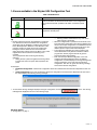
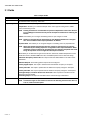
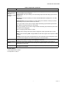
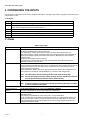
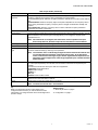
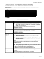
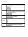
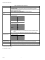
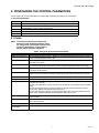
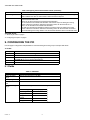
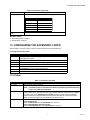
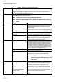
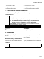
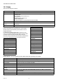
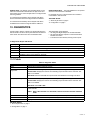
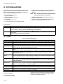
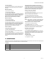
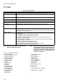
Stryker VAV User Guide
USER GUIDE
CONTENTS
1.
ABOUT STRYKER VAV............................................... 2
1.1
Overview ........................................................... 2
1.2
Features available in the Stryker VAV
Configuration Tool ............................................. 2
1.3
Acronyms and Definitions.................................. 2
1.4
Icons available in the Styker
Configuration Tool ............................................. 3
2.
CONFIGURATION ....................................................... 4
2.1
Adding a device................................................. 4
2.2
Configuring the Stryker VAV Device .................. 4
2.3
Fields................................................................. 4
3.
CONFIGURING THE OUTPUTS.................................. 5
3.1
Fields................................................................. 6
4.
CONFIGURING THE INPUTS...................................... 8
4.1
Fields................................................................. 8
5.
CONFIGURING THE SCHEDULE ..............................10
5.1
Fields................................................................ 10
6.
CONFIGURING THE TEMPERATURE SETPOINTS . 11
6.1
Fields................................................................ 11
7.
CONFIGURING THE FLOW SETPOINTS .................. 13
7.1
Procedure......................................................... 13
7.2
Fields................................................................ 13
8.
CONFIGURING THE CONTROL PARAMETERS.......15
8.1
Fields ................................................................15
9.
CONFIGURING THE PID ............................................16
9.1
Fields ............................................................... 16
10. CONFIGURING THE ACCESSORY LOOPS ..............17
10.1
Fields ................................................................17
11. CONFIGURING THE CUSTOM WIRING ....................19
11.1
Fields ................................................................19
12. ALARM VIEW..............................................................19
12.1
Fields ................................................................20
13. DIAGNOSTICS ........................................................... 21
13.1
Fields ................................................................21
14. FLOW BALANCING ....................................................22
14.1
Fields ................................................................22
15. MONITORING..............................................................23
15.1
Fields ................................................................24
16. SENSOR CALIBRATION ............................................25
16.1
Fields ................................................................25
17. SETTING TIME........................................................... 26
17.1
Fields ................................................................26
18.
ONLINE OPERATION .................................................26
62-2030-01
STRYKER VAV USER GUIDE
1. ABOUT STRYKER VAV
1.2 Features available in the Stryker
VAV Configuration Tool
1.1 Overview
You can perform the following operations using the tool:
— Set up the Stryker VAV controllers on the network
— Configure the Stryker VAV controller for the target
application
— Create applications to program the controller
— Download the configuration to the controller
— Calibrate inputs and check outputs in manual mode
— Set the time in the controllerMonitor errors and alarms
logged in the controller
— Perform online operations like sensor calibration, controller diagnostics, airflow balancing, and custom wiring.
The Honeywell Stryker VAV devices are configurable Lon
controllers that can be used to control VAV Zone terminal
boxes. These controllers also provide 2 freely configurable
PID loops to make use of any free pins in the controller. This
document describes how to configure and troubleshoot the
Stryker VAV devices using the AX Wizard. This includes
detailed descriptions of the various fields available in the
Wizard to configure an Stryker VAV controller and also a
description of the options available to check-out the points
after initial configuration.
1.3 Acronyms and Definitions
Table 1. Acronyms.
Acronym
VAV
Expansion
Variable Air Volume
NV
Lon Network Variable
PID
Proportional-Integral-Derivative (PID) values regulate an analog output based on two analog values
(one is a controlled variable; the other, a reference variable) and operating parameters.
JACE
Java Application Control Engine.
PWM
Pulse Width Modulation
DLC
Demand Limit Control
The purpose of DLC is controlling the demand so that it does not exceed the maximum contracted
demand limit.
OAT
Outdoor Air Temperature
K factor
Constant Factor
LED
Light Emitting Diode
Reheat
Reheat is used for heating purpose in case of single duct, and only in cold regions, where heating is
required.
Night Purge
During night time, the outside temperature is lower than supply air temperature. Night purge is a
process of flushing the building directly. In this process, outside dampers are opened and return air
dampers are closed and all exhaust fans are operated in full speed. It is used to save the Energy
saving and to improve the indoor air quality.
Emergency Purge
If high temperature relief is required, the Emergency purge relief is required in case of high
temperature relief, and it can be triggered by lowering the temperature or through lowering the
pressure.
62-2030—01
2
STRYKER VAV USER GUIDE
1.4 Icons available in the Stryker VAV Configuration Tool
Table 2. Available Icons.
Device Icon
Icon Status
Description
Download State
This icon indicates that the configuration from the station has been
written to the device via the Asc Download action or the configuration
from the device has been updated in the station via the Asc Upload
action.
Download Pending State
This is a download pending icon. It appears when the device is
dropped onto the Nav pane.
—
Entering numeric values that are very close to the
valid range for a given field.
• When the configuration is uploaded from the device, if the
input and output configuration in the device is different from
the input and output configuration in the database then the
user configured input and output names will be lost. The
default input and output names will be displayed.
• The progress bar indicates the current progress in the
wizard. Sometimes it may take few minutes to load the
progress bar, and the progress bar will not give the
accurate progress during loading.
• Each unit has a pre-defined configuration. If the user
configures the device different from the pre-defined
configuration, the wizard displays a warning message. The
warning message is just to notify the user about the
configuration. The user can ignore the warning message
and continue with the configuration.
Tip
• Numeric values are stored in the application in a defined
unit. When these values are loaded in the configuration
wizard they may be displayed in a different unit. Each unit
has a defined precision. Because of this difference in the
precision and the unit, there may be loss of data when
loading the numeric values into the wizard and when
saving the numeric values. This loss of data is of very small
magnitude and will not affect the functioning of the
controller.
You may experience this loss during the following
scenarios.
— Setting the unit system to English and entering values
in fields such as flow set points and temperature set
points.
For Example:
— Predefined configuration: A Series Fan configuration should be combined with the Pressure Independent air flow control.
— Actual Configuration: If the user combines the Series Fan configuration with the Pressure Dependent air flow control,
the wizard displays the following warning message.
• To view all the warning messages displayed during the configuration, click the
messages are displayed as shown in the following image.
button. The warning
RELATED TOPICS
“2. Configuration” on page 4
3
62-2030—01
STRYKER VAV USER GUIDE
2. CONFIGURATION
2.1 Adding a device
Use this page to add an Stryker VAV device to the LON network. You can add a device either in the online mode or the offline
mode.
To add an Stryker VAV device:
Step
1
2
3
4
Action
From the Lon Device Manager, click New. The New dialog box appears.
Select AscLonVAV Device from the Type to Add list.
Type one in the Number to Add box. Click Ok. The details of the device are displayed.
Enter information in the available fields.
Click Ok. You can view the newly added device under Local Lon Device items in the Nav palette.
Note: The other way to add a new device is by using the Lon Discover option.
5
2.2 Configuring the Stryker VAV Device
Use this page to configure an Stryker VAV device on the LON network. You can configure the device either in the online mode or
the offline mode.
To configure the Stryker VAV device:
Step
1
2
3
4
5
6
Action
From the Nav menu, choose Station > Driver > LON network > AscLonVAV device.
Double click AscLonVAVDevice. The VAV Configuration Wizard page appears.
Enter information in the available fields.
Click Next to display the Outputs page.
Click UndoAll to revert to the last saved settings.
Click Finish to save settings to station.
2.3 Fields
Table 3. Stryker VAV Device Fields.
Name
Definition
Controller Type
Displays the Controller Type such as With Actuator or Without Actuator.
Pressure Type
Displays the VAV Terminal Unit pressure control operation for this application. This selection defines
how the controller will operate the VAV Terminal Units damper. Valid selections for this field are:
Pressure Independent - The controller uses airflow as the primary means of controlling the VAV
Terminal Damper.
Pressure Dependent - The controller uses space temperature as the primary means of controlling
the VAV Terminal Damper.
Box Type
Displays the physical type of VAV Terminal. This selection determines what control options are
available for the VAV Terminal. Valid selections for this field are:
Single Duct: This VAV Terminal type consists of a single primary air supply inlet connection with or
without a primary flow sensor. This box type is primarily used for cooling only applications, cooling
with local reheat or dual temperature (central heating/cooling) systems.
62-2030—01
4
STRYKER VAV USER GUIDE
Table 3. Stryker VAV Device Fields. (Continued)
Name
Definition
Flow Type
Displays the control flow algorithm used by the controller. The selection available depends on the
Pressure Type and Box Type selected. Valid selections for this field are:
Flow Normal: The flow is controlled to satisfy the temperature control algorithm.
Flow Tracking: This VAV Terminal type consists of a single inlet air connection receiving its primary
source from the conditioned space. The outlet of the terminal is connected to a return air (or exhaust
air) system. The temperature control is turned off and the air flow is controlled to balance the flow
between several input vav boxes and one exhaust vav box in a room. This flow type is selectable
only when the Pressure Type is set to pressure independent.
Shared Wall Module: The temperature control loop is turned off and the flow is controlled by the
wall module at another master node. The NV nviShare of this controller must be bound to nvoShare
of the master node and the information received in nviShare is used to control the air flow. The
master node must have the temperature sensor connected to it and controls the space temperature
using its own damper and the other dampers of all nodes bound to it. This feature is used when only
one temperature sensor is used in a large area to control several boxes or when there is a need to
reprogram multiple satellite controllers based on flexible floor plans.
Wall Module Type
Displays the type of wall module to be used for this application. This selection determines the type of
control and options that are available from the wall module. Valid selections for this field are:
None: There is no physical wall module connection to this controller.
Conventional Wall Module: Select this when using the TR21, TR22 and TR23 series of wall
modules.
TR71/75 Wall Module: These wall modules provide access to configuration parameters and
schedule events.
Controller Power up
Disable Time
Enables you to set controller power disable time. The digital outputs of the controller are disabled for
this duration after power-up. This configuration is ignored by the controller when it is in emergency
mode.
Set Time During
Download
Enable this option to set the controller time during the download operation.
Daylight Savings
Settings
This feature enables you to select the Daylight Savings Settings. The available options enable you
to select Start Month, Start Day, End Month and End Day.
The tool validates the correct start and end date selection for day light savings. If the start and end
date configured is not valid then the tool displays an error and prevents the day light savings
configuration from being saved. Examples of invalid date are: February 30th, June 31st, September
31st.
RELATED TOPICS
“1. About Stryker VAV” on page 2
3. CONFIGURING THE OUTPUTS
Use this page to configure the outputs of the Stryker VAV device as well as the parameters used to control the outputs.
To configure outputs:
Step
Action
1
From the left pane of the VAV Configuration Wizard, select Outputs.
2
Enter information in the available fields.
3
Click Undo All to revert to the last saved settings.
4
Click Next to display the Inputs page.
5
Click Finish to save settings to station.
5
62-2030—01
STRYKER VAV USER GUIDE
3.1 Fields
Table 4. Output Fields.
Name
Definition
Output
Displays the list of Outputs that can be controlled such as: Damper motor, Reheat, Peripheral heat,
Fan and Wall module occupancy status LED.
Output Assignment
Displays the mode of output assignment for all output types.
Damper Motor: Enables you to select the damper motor control type as Analog Control, PWM
Control, and Floating Control.
NOTE: Floating actuators are recommended for pressure independent control since the Analog or PWM type of actuators do not provide the required resolution for achieving stable flow.
Reheat: This enables you to configure modulating reheat or upto 3 stages of reheat.
NOTE: Damper is controlled during reheat based on the 'Modulate Reheat Flow' configuration. This is available under 'Output parameters' for Reheat
Peripheral Heat: This enables you to configured staged or modulating control of peripheral heat.
NOTE: When both Reheat and peripheral heat are configured, the sequence of control is
determined by the 'Heating sequence' configuration under Output Parameters. When
modulating control is selected for peripheral heat, the minimum peripheral heat modulating valve position can be configured under Ouput Parameters.
Fan: Enables you to select the fan types such as No Fan, Series Fan, Parallel Temperature Control,
Parallel Flow Control, Parallel PWM Control fan, and Parallel speed control for float and analog.
Wallmodule Occupancy Status LED: This output controls the LED available on the TR21-series
wallmodules.
Additional Outputs: The following optional outputs can be configured:
Auxiliary Digital Output: This output is activated when the effective occupancy is 'Occupied'.
Auxiliary Pulse On: This output is pulsed when the effective occupancy changes to 'Occupied'.
Auxiliary Pulse Off: This output is pulsed when the effective occupancy changes to 'UnOccupied'.
Free Digital Output, Free Pulse On and Free Pulse Off: These outputs are controlled from the
network through nviFree1Dig.
Free Analog output: This output is controlled from the network through nviFree1Mod.
Output Name
Enables you to edit the default output name.
NOTE: A maximum length of 18 characters is allowed. The following characters are valid a-z,
A-Z, 0-9, under-score and space.
62-2030—01
6
STRYKER VAV USER GUIDE
Table 4. Output Fields. (Continued)
Name
Definition
Output Parameters
Damper Motor,
Reheat, Peripheral
Heat, Fan,
FreeAnalog and Wall
Mod LED
When these outputs are configured as Analog, PWM or floating outputs, the corresponding output
control parameters can be configured.
Analog Control: This option enables you to enter analog output mode and analog output control for
damper motor.
PWM Control: This option enables you to enter Pulse Width Modulation (PWM) period, zero scale
and full scale.
Floating Control: This option enables you to enter floating motor travel time, startup sync position,
startup delay, auto sync position and auto sync interval.
'Unocc sync Position' can be used to configure whether the floating output should be synchronized
when effective occupancy transitions to 'Unoccupied'.
'Network sync Position' can be used to configure whether the floating output should be synchronized
on an active nviFree1Dig signal.
Note on configuring reverse action for outputs:
Analog: Use the 'Analog Output control' field to configure the output ranges that map to 0-100%.
PWM: To get reverse acting PWM, configure PWM zero scale with a higher value compared to PWM
Full scale.
Floating: Use the 'Action' field to change direction of control. Alternately, the pins assigned to 'Open'
and 'Close' can be swapped in the custom wiring screen to reverse the action.
Modulate Reheat
Flow
Enables you to configure whether airflow and damper should be controlled (between minimum position
and fixed reheat position) according to the temperature control loop.
Peripheral minimum
position
This feature can be used to maintain flow in pipes that may otherwise freeze. If the outdoor air
temperature value is connected to the zone terminal, the minimum position is active when the outdoor
air temperature is below 40F.
Heating Sequence
When both reheat and peripheral heat are configured, this allows you to specify the sequence in which
these outputs are controlled.
RELATED TOPICS
“1. About Stryker VAV” on page 2
“2. Configuration” on page 4
7
62-2030—01
STRYKER VAV USER GUIDE
4. CONFIGURING THE INPUTS
Use this page to configure the inputs used by the Stryker VAV device. This page is also used to configure the optional 10-point
custom sensor curves.
To set inputs:
Step
Action
1
From the left pane of the VAV Configuration Wizard, select Inputs.
2
For configuring various inputs to be used by the controller, use the Inputs tab. The Custom Sensors tab
can be used to configure 10-point custom sensor curves.
3
Enter information in the available fields.
4
Click Undo All to revert to the last saved settings.
5
Click Next to display the Temperature Setpoints page.
6
Click Finish to save settings to station.
4.1 Fields
Table 5. Input Fields.
Name
Definition
Input
Displays the list of inputs that can be configured to be used by the controller.
The following modulating inputs can be configured:
Space temperature, outdoor air temperature, outdoor humidity, Airflow velocity pressure,
Wallmodule occupancy override, discharge temperature, supply temperature, space temperature
setpoint, space relative humidity, space CO2, static pressure, MonitorSensor and peripheral
minimum position
The following binary inputs can be configured:
Occupancy sensor, Window open sensor, heat cool changeover switch, MonitorSwitch and
Wallmodule occupancy override button.
Input Source
Enables you to select the Input Source based on input type. The input can be configured as a
sensor connected to the hardware input or as a Lon network input. Some of the inputs can also be
configured as Sylk bus inputs. If the Input source is selected as one of the following types, an
Analog or Digital pin is assigned:
20kntc, TR2x_20kntc, RH 0 to 10V dc, RH 2 to 10V dc, Pressure 0 to 5 in.Wc, Pressure 0 to 2.5
in.Wc, Pressure 0 to 0.25 in.Wc, CO2 0to2000 ppm or a generic 0-10V voltage sensor.
NOTE: You will be able to view and reassign the pins in the Custom wiring page.
NOTE: You can also configure the input source as a Sylk sensor. A maximum of 2 Sylk sensors can be connected (one TR71/T5 and one C7400S sensor).
Input Name
Using this field you can edit the default input name.
NOTE: A maximum length of 18 characters is allowed. The following characters are valid az, A-Z, 0-9, under-score and space.
Input Parameters
Space Temperature
Setpoint
The Set Point Knob Type can be configured as Absolute or Relative.
This option is applicable only when using a TR2x type of wallmodule
Zio Wall Module
Enables you to configure the clock format displayed by TR71/75 and the units used to display
temperature values.
These settings are applicable only when using a TR71 or TR75 wallmodule.
You can configure various parameters through Zio wall module. To configure the parameters you
need to go to contractor mode by entering the password in the Zio wall module. You can ignore
entering the password in the Zio wall module for every time by configuring the password in the
Contractor Mode Password field.
62-2030—01
8
STRYKER VAV USER GUIDE
Table 5. Input Fields. (Continued)
Name
Occupancy sensor
Operation
Definition
When an occupancy sensor is configured, this field enables you to configure the following control
operations to determine the behavior during scheduled unoccupied modes:
UnoccupiedCleaningCrew: Effective occupancy switches to standby for the comfort of the cleaning
crew.
ConferenceRoom: Effective occupancy stays unoccupied independent of the occupancy sensor
activity. During scheduled occupancy, occupancy sensor changes mode between standby and
occupied.
UnoccupiedTenant: When the occupancy sensor is active, effective occupancy switches to
occupied for the comfort of the tenant.
Custom Sensors
Sensor Name
You can configure custom sensor types when using third party sensors with the controller. You can
create a maximum of two sensor types. This page allows you to configure a 10-point sensor
characteristic curve.
NOTE: Once the sensor is configured, the same sensor name is updated in the Input
Source drop-down list. Go back to Input Source and select the Custom Sensor.
Sensor Type
Displays the sensor types such as Voltage, Resistive and Unconfigured.
Unit Measure
Displays all unit categories supported by the controller.
Specification Sheet Unit Allows you to select the unit used in the specification sheet of the sensor. This allows you to define
Type
the sensor characters easily by referring to the specsheet.
NOTE: The controller uses a 12-bit Analog-to-Digital converter. Please ensure that the sensor provides adequate resolution in the target control range. To get best performance, make sure that the target range of sensor signals that are important for the
application can be mapped to the entire range supported by the controller with adequate resolution.
Application Unit Type
This is the unit in which the sensor value will be read by the controller. To use the custom sensor for
any of the inputs expected by the controller, this unit needs to match the unit expected by the
controller.
These are the internal units used by the VAV control application:
Temperature: DegF Temperature
Setpoint: DDF or DegF
Humidity: %
CO2: ppm
Pressure: inches of water column
Import
Use this action to share/reuse custom sensor definitions. The user can import the custom sensor
definitions from other controllers or stations.
Export
Use this action to save the custom sensor in a text file.
NOTE: You must save the file with a .sen extension.
Tip
When you upload the input and output values of the
configured custom sensors, you will not obtain the exact
values which you configured earlier. There will be slight loss in
precision always.
Related Topics
“1. About Stryker VAV” on page 2
“2. Configuration” on page 4
9
62-2030—01
STRYKER VAV USER GUIDE
5. CONFIGURING THE SCHEDULE
Use this page to configure the schedule events and holidays to be used by the Stryker VAV device. You can also configure
occupancy override related parameters in this page.
To set schedule:
Step
Action
1
From the left pane of the VAV Configuration Wizard, select Schedule.
2
Select the Local Schedule Type from the drop-down list. The available options are Default Occupied, Default
unoccupied and Custom Schedule.
3
Select Custom Schedule to add events. You can add maximum four events in a day.
4
Click the Holiday tab to configure holidays.
5
Enter information in the available fields.
6
Click Next to display the PID page.
7
Click Undo All to revert to the last saved settings.
8
Click Finish to save settings to station.
5.1 Fields
Table 6. Schedule Fields.
Name
Definition
Local Schedule Type
The local schedule object present in the Stryker VAV device can be configured as one of three types
supported:
Default Occupied, Default Unoccupied or Custom Schedule.
Apply Event
Enables you to customize the schedule by adding or editing the events for the selected day. A
maximum of 4 events can be configured per day. Events can be configured as Occupied, Unoccupied,
No events or Standby.
Import Schedule
Enables you to import the schedule settings from external files. You can reuse the preconfigured
schedule settings.
Export Schedule
Enables you to export the schedule settings to external files.
Override Button
Behavior
Enables you to select the override behavior such as Not used, Connected with full use and Connected
for bypass options only.
NOTE: This field is configurable only when the Wall Module type selected is Conventional
wall module and the Override input is configured.
Override Duration
Enables you to enter the override duration. The time range is 0 to 1092 minutes.
Standby Mode
Operation
Enables you to select the standby mode operation such as Unoccupied for the fan and auxiliary output
and Occupied for the fan and auxiliary output.
Holiday Type
There are two types of holidays: Weekday/Month every year, and Specific date every year.
Configure Holiday
Enables you to configure holidays by setting months, weekdays and total duration of days. You can
add US, European, and Canadian holidays as well.
Holiday List
Displays the list of holidays after configuration. You can add upto 10 declared holidays in list.
Import Holiday
Enables you to import the holiday settings from an external file.
Export Holiday
Enables you to save the holiday settings in an external file.
RELATED TOPICS
“1. About Stryker VAV” on page 2
“2. Configuration” on page 4
62-2030—01
10
STRYKER VAV USER GUIDE
6. CONFIGURING THE TEMPERATURE SETPOINTS
Use this page to configure the temperature setpoints used by the Stryker VAV device and other parameters that affect
temperature control.
To configure temperature setpoints:
Step
Action
1
From the left pane of the VAV Configuration Wizard, select Temperature Setpoints.
2
Enter information in the available fields.
3
Click Undo All to revert to the last saved settings.
4
Click Next to display the Flow Setpoints page.
5
Click Finish to save settings to station.
6.1 Fields
Table 7. Temperature Setpoint Fields.
Name
Cooling Setpoint
Definition
Values for the occupied, standby, and unoccupied settings for the cooling setpoints.
NOTE: All set points must be between 50 Deg F to 90 Deg F or 10 Deg C to 32 Deg C.
Make sure that unoccupied heat < Standby heat < occupied heat < occupied cool <
Standby cool < unoccupied cool.
The following network variables are updated with the cooling set point values.
nciTempSetpoints.oocupiedCool
nciTempSetpoints.standbyCool
nciTempSerpoints.unoccupiedCool
Heating Setpoint
Values for the occupied, standby and unoccupied settings for the heating setpoints.
The following network variables are updated with the heating set point values.
nciTempSetpoints.oocupiedHeat
nciTempSetpoints.standbyHeeat
nciTempSerpoints.unoccupiedHeat
Wall Module Center
Setpoint Limits
Configuration
Configure the High and Low Setpoint Limits to be used on the wall module.
NOTE: The unit and range allowed will vary depending on the Setpoint knob type
selected in the Inputs page.
NOTE: These fields are enabled only when the wall module type is configured as "Conventional Wall Module" or "TR71/75 Wall Module" and the Space Temperature Setpoint input is configured.
The range of these fields depends on whether the wall module set point knob type is "absolute" or
"relative".
The following network variables are updated with the wall module center setpoint limits.
nciWallModCom.HighSetPt
nciWallModCom.LoeSetPt
NOTE: These nci fields are unit less since the center point value can be in Deg F, Deg C or
Delta Deg F depending on the wall module type.
Unit is Deg F for Conventional wall module with Absolute Setpoint knob
Unit is Delta Deg F for Conventional wall module with Relative Setpoint knob
Unit is Deg C for TR71/75
DLC and Setpoint
Recovery
Values for Demand limit shed setpoint shift. The space temperature cooling setpoint is shifted up
and the heating setpoint is shifted down by this value when a DLC shed command is received by
the controller.
The following network variables are updated with the DLC Setpoint Bump.
ncidlcShiftSpt.temp_diff_p
11
62-2030—01
STRYKER VAV USER GUIDE
Table 7. Temperature Setpoint Fields. (Continued)
Name
Setpoint Ramp
Definition
Values for cooling and heating setpoint ramp rates. The setpoint Ramp value ranges between 036 Deg F/Hour.
Ramp rates are used by adaptive recovery algorithm to recover heating and cooling setpoints
from their unoccupied values.
The Ramp Rate decides the rate at which the setpoint will transition from current state setpoint to
Occupied setpoint.
The following network variables are updated with the setpoint ramp.
nciRecovClg.MaxClRmp
nciRecovClg.MinClRmp
nciRecovHtg.MaxHtRmp
nciRecovHtg.MinHtRmp
OAT Ramp
Values of Outdoor Air Temperature at which the minimum and maximum setpoint ramp rates are
to be applied.
The setpoint point ramp rates are automatically calculated to be between the min and max ramp
rates as the OAT varies between min and max OAT.
The value ranges between -30 to 120 Deg F/Hour.
The following network variables are updated with the OAT ramp.
nciRecovClg.OTMxClRmp
nciRecovClg.OTMnClRmp
nciRecovHtg.OTMxHtRmp
nciRecovHtg.OTMnHtRmp
Occupancy Setpoint Limits Values for limiting the occupied heating and cooling setpoints. These are the range stops to limit
the occupied setpoint values.
Note that these range stops are also used by TR71/TR75.
The following network variables are updated with the Occupancy Setpoint Limits.
nciWallModCom.MinHtgSetPt
nciWallModCom.MaxClgSetPt
Space freeze protection
setpoint
Use wallmodule setpoint
for occupied mode
The space heating setpoint is shifted to this value when a window is opened.
The following network variable is updated with the Space freeze protection setpoint.
nciSpSpcFrz.tempP
This field can be used to configure whether the wallmodule setpoint input needs to be used or
ignored.
Note that the Wall Module setpoint is active only when the effective occupancy is Occupied or
Bypass.
The following network variable is updated with the Use wallmodule setpoint for occupied
mode.
nciWallModCom.UseWmStPt
Space temp alarm limits
Configure the high and low limits to be used to report a 'space temperature out-of-range' alarm.
The space temp alarm disable delay is the delay from a change to occupied mode.
The following network variables are updated with the Space temp alarm limits.
nciSpcTempAlm.HiLimit
nciSpcTempAlm.LoLimit
nciSpcTempAlm.Delay
RELATED TOPICS
“1. About Stryker VAV” on page 2
“2. Configuration” on page 4
62-2030—01
12
STRYKER VAV USER GUIDE
7. CONFIGURING THE FLOW SETPOINTS
Use this page to configure flow setpoints for an Stryker VAV device and other parameters that affect flow/damper control.
7.1Procedure
To set flow setpoints:
Step
Action
1
From the left pane of the VAV Configuration Wizard, select Flow Setpoints.
2
Enter information in the available fields.
3
Click Undo All to revert to the last saved settings.
4
Click Next to display the Control Parameters page.
5
Click Finish to save settings to station.
7.2 Fields
NOTE: Flow setpoints are enabled only if Pressure Type
is selected as Pressure Independent.
Table 8. Flow Setpoint Fields.
Name
Use Special SI Units
Definition
Enable this if you want to configure flow setpoints in m3/hr. This option is available only when the
workbench is configured to use metric unit system.
Setpoints
Maximum Flow Setpoint
Maximum cooling flow setpoint value.
Minimum Flow Setpoint
Minimum cooling flow setpoint during the occupied mode.
Standby Flow Setpoint
Minimum flow setpoint during the standby mode.
Maximum Reheat Setpoint Maximum reheat flow setpoint.
Note that the flow setpoints values must be configured in the order of
Minimum Flow Setpoint < Reheat Setpoint < Maximum Flow Setpoint.
Minimum Cooling Flow
Setpoint During
Unoccupied Mode
Minimum cooling flow setpoint during unoccupied mode.
Fan Flow Setpoint
Parallel fan starts after the threshold value. During the occupied mode, the fan is started when the
primary air as a percent of max flow is less than or equal to Fan Flow percent.
Duct Area
Diameter
The area of the cooling duct where the flow sensor is installed. Select Custom_Area if you want to
enter a specific value in the Area field. Duct area is calculated automatically if you select standard
duct sizes like 2_In_Round.
Area
Values for duct area in square feet. This value is calculated automatically if you select a different
diameter.
Room CO2 Level Settings (used for indoor air quality ventilation control)
Low Level
Low Room CO2 level associated with the minimum flow setpoint.
High Level
High Room CO2 level associated with the highest flow reset. When room CO2 levels vary between
the configured low and high CO2 level, the minimum air flow is adjusted proportionally.
Fraction of Maximum Air
Flow
This is the fraction of maximum airflow added to the minimum airflow setpoint while coordinating
CO2 with the effective airflow setpoint.
Set this value to zero to disable CO2 ventilation.
Others
Fresh Air Required
This is the amount of fresh air required for this zone during scheduled occupancy. This option is
enabled only if Pressure Independent type is configured.
13
62-2030—01
STRYKER VAV USER GUIDE
Table 8. Flow Setpoint Fields. (Continued)
Name
Definition
K factor
This is the VAV Box K-factor used to calculate the flow value.
IMPORTANT NOTES:
1. The K factor must be configured before starting the airflow balancing procedure.
2. The K factor must be obtained from specsheet of the terminal box manufacturer. If this is
not know, set the value to 1400.
3. Do not change the K value after the VAV box has been balanced.
4. Never set the K value to invalid or zero.
Flow Control Throttling
Range
The flow control throttling range is between 0-5000 FPM.
Flow Control Dead Band
The flow control dead band must be configured based on the damper motor speed.
For Floating actuators:
Motor Speed (sec)
Deadband (fpm)
15
125
30
65
60
30
90 to 420
20
For proportional actuators:
Model Number
Deadband (fpm)
ML7174
460
ML7287
260
ML7475
330
MN7505 or MN7510 45
NOTE: Proportional actuators are not recommended for pressure independent airflow
control.
NOTE: Set the Flow Control Dead Band to 30fpm when the airflow filter is enabled.
Maximum Analog Output
Change per second
The flow control maximum analog output change per second.This must be configured based on
the damper motor speed.
Motor Speed (sec)
maxAOchg per sec
15 to 90
1.1
180
0.56
420
0.24
Minimum Analog Output
Change per Second
This is the minimum amount the Analog Output will be changed per second for flow control.
Enable Low Flow Alarm
Enable this option, if you want the controller to track and report low air flow as an alarm.
Enable airflow filter
Enable this option to filter the air flowing inside the zone.
NOTE: Note: Set the Flow Control Dead Band to 30 fpm when the airflow filter is enabled.
RELATED TOPICS
“1. About Stryker VAV” on page 2
“2. Configuration” on page 4
62-2030—01
14
STRYKER VAV USER GUIDE
8. CONFIGURING THE CONTROL PARAMETERS
Use this page to set control parameters for an Stryker VAV device that are used to control the damper.
To set Control Parameters:
Step
Action
1
From the left pane of the VAV Configuration Wizard, select Control Parameters.
2
Enter information in the available fields.
3
Click Undo All to revert to the last saved settings.
4
Click Next to display the Schedule page.
5
Click Finish to save settings to station.
8.1 Fields
NOTE: The Pressurize, Depressurize, Night Purge,
Emergency Purge and Morning Warmup values
are configured as a percentage of maximum flow
(pressure independent) or as percentage of
damper position (Pressure dependant).
Table 9. Configuring the Control Parameter Fields.
Name
Definition
Maximum Flow Position
VAV Box Maximum damper position. Applies only to pressure dependent control mode or when a
pressure independent airflow sensor fails.
Standby Flow Position
VAV Box minimum damper position used during standby mode. Applies only to pressure
dependent control mode.
Minimum Flow Position
Zone terminal minimum cooling damper position during the occupied mode of operation. Applies
only to pressure dependent control mode or when a pressure independent airflow sensor fails.
Reheat Flow Position
VAV Box maximum damper position in Reheat mode. The cooling air damper will be at this position
at maximum reheat capacity.
Window Open
Window open damper position. When a window is open, air flow control is disabled and the flow
damper is set to this position until the space temperature drops below the temperature set point.
Night Purge
Night purge damper setting.
Morning Warmup
Warmup damper setting.
Morning Warmup Type
Enables you to select the morning warmup type to be used when a 'MorningWarmup' command is
received by the controller.
Mixed Air: The temperature control is turned off, and the damper is controlled as per the Warmup
setting.
Warm Air with Reheat: Warm air is being supplied via the duct and the temperature control is
reverse acting. ReHeat and peripheral may be turned on.
Warm Air without Reheat: Warm air is being supplied via the duct and the temperature control is
reverse acting. ReHeat is disabled however peripheral heat may be used.
Pressurize
Damper setting to be used when a Pressurize Command is received over the network for smoke
control operation.
Depressurize
Damper setting to be used when a De-Pressurize Command is received over the network for
smoke control operation.
Emergency Purge
Damper setting to be used when an Emergency Purge Command is received over the network.
Unoccupied Minimum
Flow Position
Minimum damper position to be used during unoccupied mode.
15
62-2030—01
STRYKER VAV USER GUIDE
Table 9. Configuring the Control Parameter Fields. (Continued)
Name
Flow Tracking Offset
Definition
Represents the flow tracking offset value used when FlowType is configured as FlowTracking. This
offset is added to the value of nviFlowTrack to determine the flow setpoint.
Terminal load calculation Enables you to perform the terminal load calculation. You have the option to select 0 or 1 in the
Terminal load calculation field.
Select 0 to use the conventional zone terminal load calculation.
The conventional zone terminal load calculation uses the PID output of heating and cooling
controls. When the controller is switched to the heating mode, the Terminal load is ? 0.
Select 1 to use the CZS zone terminal load calculation.
The CZS zone terminal load calculation uses the proportional output of heating and cooling
controls. When the controller is switched to the heating mode, the Terminal Load continues to
report both heating and cooling demand. The terminal load absolute value is truncated at 100%.
RELATED TOPICS
“1. About Stryker VAV” on page 2
“4. Configuring the Inputs” on page 8
9. CONFIGURING THE PID
Use this page to configure the PID parameters for both the heating and cooling loops in a Stryker VAV device.
To set PID:
Step
Action
1
From the left pane of the VAV Configuration Wizard, select PID.
2
Enter information in the available fields.
3
Click Next to display the Accessory Loops page.
4
Click Undo All to revert to the last saved settings.
5
Click Finish to save settings to station.
9.1 Fields
Table 10. PID Names.
Name
Definition
Cooling Throttling
Range
Value must be between 2 to 30 DDF.
Cooling Integral Time
Value must be between 0 to 9000 sec.
Cooling Derivative
Time
Value must be between 0 to 9000 sec.
Heating Throttling
Range
Value must be configured based on reheat configuration.
Reheat Type
62-2030—01
TR (DegF)
modulating
5
1 stage
3
2 stage
4
3 stage
7
4 stage
8
16
STRYKER VAV USER GUIDE
Table 10. PID Names. (Continued)
Name
Definition
Heating Integral Time
Value must be configured based on reheat configuration.
Reheat Type
Heating Derivative
Time
Integral Time (sec)
modulating
2400
1 stage
3100
2 stage
2500
3 stage
1650
4 stage
1200
Value must be between 0 to 9000 sec.
RELATED TOPICS
“1. About Stryker VAV” on page 2
“2. Configuration” on page 4
10. CONFIGURING THE ACCESSORY LOOPS
Use this page to configure accessory loops for Stryker VAV device on the LON network.
To configure Accessory Loops:
Step
Action
1
From the left pane of the VAV Configuration Wizard, select Accessory Loops.
The Loop1 page appears.
2
Enter information in the available fields.
3
From the menu bar, click Loop2. The Loop2 page appears.
4
Enter information in the available fields.
5
Click Next to display the Custom wiring page.
6
Click Undo All to revert to the last saved settings.
7
Click Finish to save settings to station.
10.1 Fields
Table 11. Accessory Loop Fields.
Name
Loop Name
Definition
Enter a custom name for the loop.
NOTE: A maximum length of 18 characters is allowed. The following characters are valid
a-z, A-Z, 0-9, under-score and space.
Outputs
Accessory loop can be configured to drive a modulating output, upto 3 staged outputs and an
auxiliary digital output. The outputs can be configured only when the required pins are available/
free. Please refer the "3. Configuring the Outputs" section to configure output parameters.
Staged Control action: Staged outputs can be configured with either as conventional staged
outputs or as staged outputs with thermostat using 3 Cycles per Hour.
Inputs
Please refer the "4. Configuring the Inputs" section.
To use shared inputs:
Select the Shared Input from the Input Name drop down list.
To use main application output as an input:
Select the Main Application from the Input name drop down list.
17
62-2030—01
STRYKER VAV USER GUIDE
Table 11. Accessory Loop Fields. (Continued)
Name
Definition
Setpoint
Configure the setpoints to be used by the loop in different occupancy modes. Configure the
minimum and maximum reset values to be used and the corresponding reset sensor values.
Reset value to be added to the setpoint is calculated by the controller as a value between min max
reset values in proportion to the reset sensor value.
Control Parameters
Parameters that affect the output and the loop behavior can be configured. Below are the
configurable parameters and its descriptions.
NOTE: If derivative time is set to zero, it disables derivative action.
NOTE: Modulating output threshold value for activating the Auxiliary output can be configured to control the auxiliary output based on the value of PID loops modulating
output.
Control Parameters
Control Parameters
Configurable Parameters
Description
Throttling range
This is the proportional change in the sensed variable
required to change the control output from 0 to 100 percent.
This needs to be configured in the engineering unit of the
main input sensor
Integral time
This determines the integral gain of the PID loop. The
greater the time in seconds, the less the integral change per
second. A setting of 0 eliminates the integral function.
Derivative time
Determines the derivative gain in a PID loop. The greater the
time in seconds, the greater the derivative effect per second
PID action
Direct Acting or Reverse Acting selection determines the
behavior of the loop output. In a direct acting control loop the
output increases as the input sensor value rises above the
setpoint. In a reverse acting control loop the output
increases as the input falls below the setpoint.
Aux DO action
This determines the Aux DO behavior. The Aux output can
be configured for either continuous or intermittent operation.
This selection applies to occupied and standby modes only.
Unoccupied is always intermittent. In continuous operation
the output is continuous, regardless of the operation of the
other outputs of the loop. In intermittent operation the output
is on only when the modulating output of the loop is greater
than 0 or at least one of the staged outputs is on.
Modulating control for Aux
This option allows the Aux DO to be controlled based on the
value of the loops modulating output.
Modulating output threshold for Aux Modulating output threshold value for controlling the
Auxiliary output. The Aux DO is activated if the PID
modulating output is greater than the threshold value
Aux output minimum off time
The auxiliary digital output minimum off time.
NOTE: When staged outputs are configured this value
must be configured to be less than (Cycler and
stager interstage minimum on time - Aux output
run on time).
Control Parameters
62-2030—01
Aux output run on time
The auxiliary digital output run-on time. A value of 0 disables
the run-on time. This is typically used when the AuxDo is
configured for intermittent operation.
For example, If the AuxDO is controlling the fan, this
parameter can be used to keep the fan running for certain
duration after the cooling or heating process has stopped.
Minimum off time
This is the minimum off time for the staged outputs
Cycler and stager interstage
minimum on time
This is minimum amount of time a lower numbered stage
must be on before the next stage can turn on.
Minimum on time
This is the minimum on time for the Aux DO and staged
outputs
18
STRYKER VAV USER GUIDE
Related Topics
“1. About Stryker VAV” on page 2
“4. Configuring the Inputs” on page 8
“2. Configuration” on page 4
“6. Configuring the Temperature Setpoints” on page 11
“3. Configuring the Outputs” on page 5
“8. Configuring the Control Parameters” on page 15
11. CONFIGURING THE CUSTOM WIRING
Use this page to customize the wiring/pin assignment of IOs for an Stryker VAV device on the LON network.
The custom wiring is allowed only for the inputs and outputs parameters that are configured.
To configure custom wiring:
Step
Action
1
From the left pane of the VAV Configuration Wizard, select Custom Wiring.
2
To reassign inputs or outputs to different pins, simply select the input/output in the relevant drop-down.
Click Terminal Overlay Diagram to generate the terminal overlay diagram.
NOTE: Note: The terminal overlay diagram is formatted to match the size of the terminal overlay
present on the controller. Only 6 characters will be displayed in the generated terminal overlay diagram.
This allows you to print the Terminal Overlay to use it on the relevant controller.
3
4
Click Wiring Diagram to see the wiring between inputs and outputs. This wiring diagram shows how the
controller is connected with the external inputs and outputs.
5
Click Undo All to revert to the last saved settings.
6
Click Finish to save settings to station.
11.1 Fields
RELATED TOPICS
“1. About Stryker VAV” on page 2
None
“2. Configuration” on page 4
12. ALARM VIEW
This means that several different errors of the same type will
be reported as a single alarm.
Use this page to view errors logged by the Stryker VAV device.
This action can be performed only when the device is in the
online mode.
For Example: Multiple sensors connected to the controller
may read invalid values and the controller will log individual
errors for each sensor.
The controller must be in a commissioned state.
NOTE: Note: The controller is capable of tracking and
reporting several types of errors.
However a single 'SensorFailure' alarm will be reported.
This page displays all the errors that are currently active and
reported by the controller.
Groups of errors of the same type are also reported as an
alarm by the controller using nvoAlarmH.
To view alarms:
Step
Action
1
From the Nav menu, choose Station > Driver > LON network > Stryker VAV device.
2
Right-click the device and choose Views > Alarms View from device items. The Alarm screen appears.
19
62-2030—01
STRYKER VAV USER GUIDE
12.1 Fields
There are five categories of alarms:
Name
Definition
Error
Displays the name of the error.
Type of error
Displays the type of the error. Errors could be one of the following types:
1. Sensor Error
2. Lon Network Communication Error
3. Control Error
4. Sylkbus communication error
5. Node disabled error
For more information, see the descriptions below this table.
Details
This is a description of the error.
Enable Auto Alarm
Refresh
When the Auto Refresh checkbox is selected, the alarms view/data refreshes automatically every
30 seconds.
Refresh
Click Refresh to refresh the error list manually and see the current errors.
Sensor Errors: These errors are generated for all the sensors
that are connected to the onboard UI pins in the controller.
Network Variable
nviOdTemp
All such sensors are monitored by the controller for out-ofrange/invalid values.
nviSetPoint
Lon Network Communication Errors: These errors can
occur for Lon NetworkVariable Inputs that are bound to other
controllers when the source controller fails to send the
data.The controller tracks and reports network communication
errors for the following list of NVs when they are bound:
nviSpaceCO2
nviShare
nviSpaceHum
nviSpaceTemp
nviSupplyTemp
nviTodEvent
Network Variable
nviBypass
nviWindow
nviApplicMode
nviFlowOverride
nviDlcShed
nviSupplyTemp
nviDschrgAirTemp
nviMonDig
nviFan
nviManOcc
nviFlowOffset
nviEmergCmd
nviFlowTrack
nviSetPointOvr
nviFree1Dig
nviSetPtOffset
nviFree1Mod
nviMonSensor
nviOccCmd
Control Alarms: These are application specific alarms tracked and reported by the controller.
Alarm Name
Alarm Description
Frost
The space temperature detected is below the freeze protect limit.
Invalid Set Point
One of the temperature set points is not in the valid range.
Flow Override
The air flow control loop has been overridden.
Emergency Override
An emergency override command has been received from the network.
Fan Override
The fan is in the manual override state.
Reheat or Peripheral Heat
Override
The reheat or peripheral heat outputs are overridden.
IAQ alarm
The indoor air quality sensor has detected that the indoor air quality is poorer than the
desired standard.
Occupied Space Temperature
The space temperature detected is out of range of the configured limits.
Low Air Flow
Air flow detected is too low to perform the flow control operation.
62-2030—01
20
STRYKER VAV USER GUIDE
Sylkbus Alarm: The Sylkbus communication alarm occurs
when the communication link between the Sylk sensor and
the controller is lost or when the Sylk sensor is configured with
the wrong address.
5Node disabled Error: The node disabled error is reported
when the control execution is disabled.
For example, this error is reported when the controller is
commanded to manual mode.
To communicate successfully with an Stryker VAV device,
TR71/TR75 devices must be configured with the address 1.
RELATED TOPICS
“1. About Stryker VAV” on page 2
To communicate successfully with an Stryker VAV device,
C7400S sensors must be configured with the address 8.
“2. Configuration” on page 4
13. DIAGNOSTICS
Use this page to test the outputs of an Stryker VAV device in
manual mode. This action can be performed with the device in
online mode. The device must be in downloaded state.
The Diagnostics screen displays:
• All configured Digital Outputs to command ON/OFF
• All configured Analog Outputs to command the values
between 0 to 100%
• The values that are sensed (currently) at the outputs
To diagnose an Stryker VAV device:
Step
Action
1
From the Nav menu, choose Station > Driver > LON network > AscLonVAV device.
2
Right-click the device and choose Views > Diagnostics from device items. The Diagnostics screen appears.
3
Enter information in the available fields.
4
Click Refresh to reset the settings.
5
Click Set to set the output values for diagnosis.
13.1 Fields
Table 12. Diagnostic Fields.
Name
Definition
Name
Displays the configured parameter names.
Modulating Output
Diagnostics
The number of Modulating Outputs depends on the outputs configured in the application.
Current Value: Displays the value of the modulating output as read from the controller. This
field is non-editable.
Edit Value: Enter the value that the output must be commanded to. The range is 0-100 %.
Binary Output Diagnostics
The number of Binary Outputs depends on the outputs configured in the application.
Current Value: Displays the value of the modulating output as read from the controller. This
field is non-editable.
Edit Value: Select ON or OFF.
Set
Click Set. The controller is set to 'Manual' control and the commanded output values are written
to the controller.
NOTE: Note: If the controller is in Auto mode, click Set to set the controller to Manual
mode.
Auto Refresh
Select the Auto Refresh checkbox to automatically refresh the output values every 30 seconds.
Refresh
Select the Refresh to refresh the output values, only when the device is in manual mode.
Current Mode
Displays the current mode of the device.
RELATED TOPICS
“1. About Stryker VAV” on page 2
“2. Configuration” on page 4
21
62-2030—01
STRYKER VAV USER GUIDE
14. FLOW BALANCING
• VAV Zone Terminal Single Duct must be selected as the
Application Type and Air Balance Supported must be
selected.
The flow balancing view is used to balance a controller that is
programmed with a standard VAV application. Based on the
version of the VAV application and its features, the following
operations can be performed on the view.
•
•
•
•
•
•
•
NOTE: Note: The selections must be done before downloading the program to the controller.
Flow pressure zero calibration
Two point calibration
K factor calibration
Heating coil water flow calibration.
Pre-requisites
The controller must be online.
The controller must be in a commissioned state.
• Select the Reheat Valve Override Supported option to
calibrate the reheat valve.
• Select the Peripheral Heat Valve Override Supported
option to calibrate the peripheral heat valve.
To flow balance:
Step
Action
1
On the Nav palette, browse to Station > Config > Drivers> LonNetwork > LonDevice.
or
Browse to Station > Config > Drivers> BacnetNetwork > BacnetDevice.
2
Right-click ControlProgram and select Views > Flow Balancing View. The Flow Balancing View appears on
the right pane.
You can type the values into the following fields.
14.1 Fields
Table 13. Flow Balancing Fields.
Name
Description
Actuator Travel Time The actuator travel time is the time required by the actuator to travel from 0% to 100% open or 100% to
0% open. This time interval depends on the actuator type and can vary from 0 to 500 seconds.
K Factor
This field allows you to manually change the K factor value from 0 to 10000.
Inlet Area
Displays the area of the duct. Either a standard diameter can be selected or a custom area can be
entered in this field. The inlet area ranges from 0 to 100 sq.ft.
Measured Flow
Displays the actual air flow when measured by the balancer using an accurate device. This field is
editable.
Maximum Flow
Setpoint
This field allows you to set the flow setpoint from 0 to 138850 cfm for maximum flow calibration and k
factor calibration. The controller seeks stable flow and when it is reached, it allows you to set the
calibration source value.
Minimum Flow
Setpoint
This field allows you to set the flow setpoint value from 0 to 138850 cfm. You must set the flow setpoint
less than the maximum value to obtain minimum flow calibration. The controller seeks stable flow and
when it is reached, it allows you to set the calibration source value.
Re-heat Valve
Override
This field allows to override the value of the reheat valve in an application built for the reheat valve. This
field is visible when the Reheat Valve Override Supported feature is selected in the Details View of
the Control Program.
Peripheral Heat
Valve Override
This field allows to override the value of the peripheral heat valve in an application built for the
peripheral heat valve. This field is visible when the Peripheral Heat Valve Override Supported feature
is selected in the Details View of the Control Program.
Device Mode
Displays the current device mode. This is a non-editable field.
Damper Position
Displays the current damper position. This is a non-editable field.
Sensed Flow
Displays the actual air flow that is measured by a pressure sensor. This field is non-editable.
Flow Pressure
Displays the current flow pressure. This field is non-editable.
Flow pressure zero calibration
The damper is completely closed. If any flow pressure is
detected, that value is considered to be the flow pressure
offset. After the completion of zero balancing, the device
mode is set to automatic operation.
To start zero balancing:
Click Start Zero Balancing.
62-2030—01
22
STRYKER VAV USER GUIDE
Two point calibration
After the measured flow is entered, the K factor value is
calculated by the tool and displayed. The tool prompts you to
write this value to the device. You can choose to calculate the
K factor without using the tool and set the calculated value in
the K factor field. The device remains in manual mode (Open
Maximum) after K factor balancing has been completed.
You can start either maximum or minimum balancing in any
order. The tool does not enforce any rules on the order of
balancing.
Maximum calibration
Heating coil water flow calibration
To start maximum calibration:
To override the reheat valve position:
Click Start Maximum Balancing.
Type the reheat value in percentage and click the Override
button next to Reheat Valve Override field.
The device adjusts the damper to try and attain the maximum
flow setpoint. After the setpoint is attained, the Measured Flow
field is enabled and the actual measured flow value can be
entered. The device remains in manual mode (Open
Maximum) after maximum balancing is complete.
To override the peripheral heat valve position:
Type the peripheral heat value in percentage and click the
Override button next to the Peripheral Heat Valve Override
field.
Minimum calibration
To start minimum calibration:
NOTE: Note: Click the Auto button to set the reheat and
peripheral heat valve into automatic operation.
Click Start Minimum Balancing.
Setting the device mode to automatic operation
The device adjusts the damper to try and attain the minimum
flow setpoint. After the set point is attained, the Measured
Flow field is enabled and you can enter the actual measured
flow value. The device remains in manual mode (Open
Minimum) after minimum balancing is complete.
To set the device to automatic operation:
Click Set Mode to Auto when it is enabled.
K Factor calibration
While exiting the view if the device is in manual mode, the tool
prompts you to change the mode to automatic operation.
To start K factor calibration method:
Restoring to factory defaults
Click Start K Factor Balancing.
To restore to factory defaults:
After a warning message, the two point calibration data is
returned to factory defaults.
Click the Restore to Factory Defaults button to restore the
default value of the Zero calibration values, K factor calibration
values, Minimum flow calibration values and Maximum flow
calibration values.
The device adjusts the damper to try and attain the maximum
flow setpoint. After the setpoint is attained, the Measured Flow
field is enabled and the actual measured flow value can be
entered.
RELATED TOPICS
“1. About Stryker VAV” on page 2
“2. Configuration” on page 4
15. MONITORING
Use this page to monitor the critical parameters for an Stryker VAV device on the LON network. This action can be performed with
the device in online mode. The controller must be in a commissioned state.
To monitor:
Step
Action
1
From the Nav menu, choose Station > Driver > LON network > AscLonVAV device.
2
Right-click the device and choose Views > Monitor from device items. The Monitor screen appears.
3
If required, you can enter the values in the editable fields.
4
Click Write to write edited values to the controller.
23
62-2030—01
STRYKER VAV USER GUIDE
15.1 Fields
Table 14. Monitoring Fields.
Name
Definition
Name
Displays the configured parameter names.
Read Value
Displays the current value read from the controller.
Write Value
Enables you to write the expected value to the controller.
Current Mode
Displays the current mode of the controller.
Units
Displays the respective units of the parameters.
Current Mode
This fields displays whether the controller is in manual control or in auto mode.
Temperature set point
You can temporarily change/override the setpoint using this field. Enter the setpoint value and
click the Write button at the bottom of the screen. To remove the temporary override, type 'Nan'
in this field and click the Write button.
Application Mode
This field can be used to switch between off, auto, heating and cooling. The following options
can be selected.
Auto - Enable this option for auto reheating and cooling
Heat - Enable this option to supply warm air and reheat
Morning warmup - Enable this option to supply warm air and to trigger reheat as per the
'Morning warmup type' configured.
Cool - Enable this option to supply cool air and lock reheat. Use this mode to disable reheat
when boiler hot water is unavailable.
Night purge - Enable this option to supply outdoor air.
Off - Enable this option to off fan, heating and cooling.
Fan only - Enable this option to enable only fan, no heating or cooling.
Note that all other options are ignored by the controller.
NOTE: Note: Only configurable parameters are displayed in the Monitoring screen.
NOTE: Note: For the Monitor Sensor input the value will
be displayed as reported from the controller even
if the value lies outside the range of the sensor
type that is configured. If the value reported from
the controller is +inf or –inf or NaN then the text
Invalid will be displayed.
The list of configurable parameters is
• Temporary set point
• Effective temperature set point
• Scheduled Occupancy
• Sensed Occupancy
• Effective Occupancy
• Manual Occupancy
• Application Mode
• Box Flow
• Damper Position
• Fan Speed
• Fan Status
• Heating Stages On
• Reheat percentage
• DLC shed status
• Space Temperature
• Supply Temperature
• Discharge Air
• Peripheral Heat
62-2030—01
•
•
•
•
•
•
•
•
•
•
Outdoor air temperature
Monitor Switch
Free Digital Output
Window Open
Heat Cool Switch
Auxiliary Digital Output
Free 1 Modulating
Monitor Sensor
Space CO2
Space Relative humidity
Related Topics
“1. About Stryker VAV” on page 2
“2. Configuration” on page 4
24
STRYKER VAV USER GUIDE
16. SENSOR CALIBRATION
Use this page for sensor calibration in an Stryker VAV device on the LON network. Using Sensor Calibration feature, you can
correct the input values to the controller. This action can be performed with the device in online mode. The controller must be in a
commissioned state. While performing Sensor Calibration, the device should not be used by another application. You can
calibrate only analog inputs to the controllers.
To calibrate:
Step
Action
1
From the Nav menu, choose Station > Driver > LON network > AscLonVAV device.
2
Right-click the device and choose Views > Sensor Calibration from device items. The Sensor
Calibration screen appears.
3
Enter information in the available fields.
4
Click Refresh to refresh the settings.
5
Click Calibrate to calibrate settings.
16.1 Fields
Table 15. Sensor Calibration Fields.
Name
Definition
Sensor Name
Displays the sensor names.
Actual Value
Displays the current value of the sensor as read by the controller.
Calibrated Value
Enter the calibrated value.
Offset Value
Once you click Calibrate, the offset value appears. Offset value is a difference between
Actual value and Calibrated value.
Tip
In this case
To clear the Offset value for any of the configured
sensors:
Calculate the calibrated value using the below formula, type it
in the Calibrated value field and click Calibrate.
The Actual value = -324.742
Old Offset value = 775.102
Calibrated Value = Actual Value - Old Offset Value
Calibrated Value = Actual Value - Old Offset Value
= -324.742-775.102
For Example:
= -1099.844 F
If the configured Sylk bus sensor reads the room temperature
as 79.88 F and you want to calibrate it to 85.5 F. By mistake if
you type the calibrated value as 855 F, the offset value will be
calculated as 775.102 F. This will display the Actual value as 324.742 which is abnormal.
If you type this value in the Calibrated Value field and click
Calibrate, the Offset value will be cleared.
RELATED TOPICS
“1. About Stryker VAV” on page 2
If you find any abnormal value like this and you want to clear
the offset value. Calculate the Calibrated value as shown
below and type the calculated value in the Calibrated Value
field.
“2. Configuration” on page 4
25
62-2030—01
STRYKER VAV USER GUIDE
17. SETTING TIME
Use this page to set time for an Stryker VAV device on the LON network. This action can be performed with the device in online
mode. The controller must be in a commissioned state. Using Set Time feature, you can specify time or use the computer's time
in the controller. While performing this online operation, the device should not be used by another application.
To set time parameters:
Step
Action
From the Nav menu, choose Station > Driver > LON network > AscLonVAV device.
1
2
Right-click the device and choose Views > Set Time from device items.
3
The Set Time screen appears.
4
Enter information in the available fields.
5
Click Apply to set date and time in device.
17.1 Fields
Table 16. Time Fields.
Name
Definition
Date
This option enables you to set date in the controller.
Time
This option enables you to set time in the controller.
RELATED TOPICS
“1. About Stryker VAV” on page 2
“2. Configuration” on page 4
18. ONLINE OPERATION
The online operations can be invoked on the Stryker VAV
device only if the device is not in use by another application.
You can perform following online operations:
1. Download - Perform this action to download the configuration from tool to controller.
2. Upload - Invoke this option to read configuration data
from the controller and update the same in the tool database.
3. Calibration - Use this option to calibrate the sensor
connected to the controller.
4. Diagnostics - Use this feature to command the device
to manual mode and to test the outputs.
5. Set Time - Use this option to set the date and time in
the controller.
6. Flow Balancing - The flow balancing feature allows
minimum balancing, maximum balancing, zero balancing and k factor balancing.
You can also balance the reheat and peripheral heat
62-2030—01
7.
8.
valves.
You can also reset the balancing values to factory
defaults.
Monitoring - Use the monitoring option to view key
parameters in the controller.
You can also temporarily override setpoints and occupancy status.
Alarms - Use the Alarms option to view the list of
alarms generated by the controller.
Related Topics
“13. Diagnostics” on page 21
“14. Flow Balancing” on page 22
“15. Monitoring” on page 23
“16. Sensor Calibration” on page 25
“17. Setting Time” on page 26
26
STRYKER VAV USER GUIDE
27
62-2030—01
STRYKER VAV USER GUIDE
Automation and Control Solutions
Honeywell International Inc.
1985 Douglas Drive North
Golden Valley, MN 55422
customer.honeywell.com
® U.S. Registered Trademark
© 2012 Honeywell International Inc.
62-2030—01 M.S.
05-12
Printed in United States