1
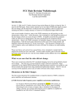
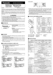
Amplifier Built-in Ultra-slim
Photoelectric sensor
EX-10 Series
USER’S MANUAL
WUME-EX10-4
2013.10
http://panasonic.net/id/pidsx/global
Contents
1. Safety precaution········································································ 3
2. Part Description·········································································· 4
3. Mounting······················································································ 6
3-1 Mounting of the sensor··························································· 6
3-2 Mounting interval···································································· 7
4. I/O Circuit Diagram··································································· 13
5. Stability Indicator······································································ 14
6. Beam alignment········································································ 14
7. Option························································································ 15
7-1 Slit Mask (optional)······························································· 15
7-2 Sensor mounting bracket (optional)······································ 15
8. Specifications············································································ 16
8-1 Standard-beam type····························································· 16
8-2 Narrow-beam type································································ 18
9. Dimentions················································································ 19
2
1. Safety precaution
WARNING
●● Never use this product as a sensing device for personnel protection.
●● In case of using devices for personnel protection, use products which meet laws and
standards, such as OSHA, ANSI or IEC etc., for personnel protection applicable in
each region or country.
●● This product has been developed / produced for industrial use only.
●● The narrow beam type EX-1□S□ emits a narrow light beam, so it is difficult to align the beam. Use
the instrument with the emitter and the receiver facing each other in a straight line. Note that if
screws or other parts become loose due to vibration, for example, the beam axis may drift.
●● Sensor mounting baracket (optional) MS-EX-10-□ is an object for satandard-beam type.
It cannot be used for narrow-beam type.
●● For the convergent reflective type EX-14□, if there is a reflective object (e.g., a conveyor, etc.) in
the background of the sensing object, since it may affect the sensing, use by keeping enough distance from the reflective object.
●● The thin cable 0.1mm2 is used for this product. Thus, take care that if the cable is pulled with excessive force, it may cause cable break.
●● Extension up to total 50m (each emitter and receiver of thru-beam type), or less, is possible with
0.3mm2, or more of conductor area cable. However,the extension of a power supply line and the
output line of less than 10m is acceptable in case using this product as conforming to S-mark.
●● Make sure that stress by forcible bend or pulling is not applied directly to the sensor cable joint.
●● Make sure to carry out wiring in the power supply off condition.
●● Take care that wrong wiring will damage the sensor.
●● Verify that the supply voltage variation is within the rating.
●● If power is supplied from a commercial switching regulator, ensure that the frame ground (F.G.)
terminal of the power supply is connected to an actual ground.
●● In case noise generating equipment (switching regulator, inverter motor, etc.) is used in the vicinity
of this product, connect the frame ground (F.G.) terminal of the equipment to an actual ground.
●● Do not run the wires together with high-voltage lines or power lines, or put them in the same raceway.
●● Take care that the sensor is not directly exposed to fluorescent lamp from a rapid-starter lamp, a
high frequency lighting device or sunlight etc., as it may affect the sensing performance.
●● Do not use during the initial transient time (EX-15□, EX-15E□, EX-17□, EX-17E□: 100ms / others:
50ms) after the power supply is switched ON.
●● This sensor is suitable for indoor use only.
●● Do not use this sensor in places having excessive vapor, dust, etc., or where it may come in contact with corrosive gas, etc.
●● Take care that the product does not come in contact with oil, grease, organic solvents such as
thinner, etc., strong acid or alkaline.
●● This product cannot be used in an environment containing inflammable or explosive gasses.
●● Never disassemble or modify the product.
●● Since the cable end is not waterproof, do not use the sensor in the application where water may
seep in from the cable end.
3
2. Part Description
Thru-beam front sensing type: EX-11□ , EX-13□ , EX-19□,
EX-11S□ , EX-13S□ , EX-19S□
Stability indicator
(Green)
Operation indicator
(Orange)
Mounting
hole
Beam
emitting
part
Beam
receiving
part
<Emitter>
Mounting hole
<Receiver>
Thru-beam side sensing type: EX-11E□ , EX-13E□ , EX-19E□
EX-11SE□ , EX-13SE□ ,
Stability indicator
(Green)
Operation indicator
(Orange)
Beam
receiving part
Mounting hole
Beam
emitting
part
<Receiver>
<Emitter>
Convergent reflective front sensing type: EX-14□
Beam emitting part
Stability indicator
(Green)
Operation indicator
(Orange)
Mounting hole
Beam receiving part
4
Mounting
hole
Thru-beam front sensing type with
operation mode switch on bifurcation:
EX-15, EX-17
<Emitter>
Mounting
hole
Thru-beam side sensing type with
operation mode switch on bifurcation:
EX-15E, EX-17E
<Receiver>
Stability indicator (Green)
Operation indicator(Orange)
Mounting
hole
Beam Beam
emitting receiving
part
part
Operation mode switch
Operation indicator
(Orange)
<Emitter>
Mounting
hole
<Receiver>
Beam
emitting
part
Beam
receiving
part
Mounting
hole
Stability indicator
(Green)
Operation indicator
(Orange)
Operation mode switch
Operation indicator
(Orange)
<Operation mode switch>
Operation mode switch
L: Light-ON
D: Dark-ON
Operation indicator (Orange)
Light up when the output is ON.
Switch position
Operation
Description
Light-ON
Light-ON mode is set when the switch is turned fully clockwise (L side).
Dark-ON
Dark-ON mode is set when the switch is turned fully counterclockwise
(D side).
5
3. Mounting
3-1 Mounting of the sensor
●● The tightening torque should be 0.2 N·m or less.
●● The narrow beam type EX-1□S□ emits a narrow light beam, so it is difficult to align the beam.
Note that if screws or other parts become loose due to vibration, for example, the beam axis may
drift.
●● In case of mounting on tapped holes (Unit: mm)
Front sensing
Side sensing
Sensing
direction
Sensing
direction
11
11
M2 × 0.4
tapped, 7 deep
M2 screw
[length 8(accessory)]
M2 screw
[length 10(accessory)]
●● In case of using attached screws and nuts (Unit: mm)
Front sensing
Side sensing
Spring washers
(accessory)
Nuts
(accessory)
Flat washers
(accessory)
Thickness of mounting
plate: 2.5 or less
Sensing
direction
Sensing
direction
11
11
M2 screw
[length 8(accessory)]
M2 screw
[length 10(accessory)]
M2 × 0.4
tapped, 6 deep
Spring washers
(accessory)
Nuts
(accessory)
Flat washers
(accessory)
Thickness of mounting
plate: 2 or less
●● In case of using mounting bracket (optional)
The sensor bracket is an object for satandard-beam type. It cannot be used for narrowbeam type.
MS-EX-10-1
MS-EX-10-2
MS-EX-10-3
Material: SPCC (Uni-chrome plated)
Two M2 (length 4 mm) pan
head screws (Accessory)
MS-EX-10-11
6
Material: SUS304
Two M2 (length 4 mm) pan
head screws (Accessory)
Material: SPCC (Uni-chrome plated)
Two M2 (length 8 mm) pan
head screws (Accessory)
MS-EX-10-12
Material: SUS304
Two M2 (length 8 mm) pan
head screws (Accessory)
Material: SPCC (Uni-chrome plated)
Two M2 (length 4 mm) pan head screws
Two M2 (length 8 mm) pan head screws
Accessory: 2 pan head screws each
MS-EX-10-13
Material: SUS304
Two M2 (length 4 mm) pan head screws SUS304
Two M2 (length 8 mm) pan head screws SUS304
Accessory: 2 pan head screws each
3-2 Mounting interval
●● This product does not incorporate auto interference function. In case mounting two sets
or more of the this product close together, please mount them as drawing below indicates (typical example)
●● Find out the operating point ℓ on the parallel deviation diagram for the setting distance L.
Separate sensors by 2 × ℓ or more.
Thru-beam type: EX-11□, EX-15□, parallel deviation diagram (typical)
Sensing distance L (mm)
200
<Installation interval for EX-11□, EX-15□>
In case using at sensing distance (L1) 150mm, the operation point (ℓ1) is approx. 23.4mm according to diagram above.
The installation interval is
Approx. 23.4mm × 2 = approx. 46.8mm
Thus, install approx.46.8mm or more away.
(L1)
150
100
(ℓ1)
50
0
100
150mm
50
0
50
100
Emitter
Right
Left
Center
Operating point ℓ (mm)
Receiver
EX-11□,EX-15□: Approx. 46.8mm or more
EX-11□,EX-15□: Approx. 46.8mm or more
Thru-beam type: EX-11E□, EX-15E□, parallel deviation diagram (typical)
Sensing distance L (mm)
200
150
<Installation interval for EX-11E□, EX-15E□>
In case using at sensing distance (L2) 150mm, the
operation point (ℓ2) is approx. 15mm according to diagram above.
The installation interval is
Approx. 15mm × 2 = approx. 30mm
Thus, install approx. 30mm or more away.
(L2)
100
50
0
100
(ℓ2)
50
0
50
100
Right
Left
Center
Operating point ℓ(mm)
150mm
Emitter
Receiver
EX-11E□,EX-15E□: Approx. 30mm or more
EX-11E□,EX-15E□: Approx. 30mm or more
7
Thru-beam type: EX-13□, EX-17□ parallel deviation diagram (typical)
Sensing distance L (mm)
800
600
(L3)
400
(ℓ3)
200
0
100
50
0
50
<Installation interval for EX-13□,EX-17□>
In case using at sensing distance (L3) 500mm, the
operation point (ℓ3) is approx. 76.6mm according to
diagram above.
The installation interval is
Approx. 76.6mm × 2 = approx. 153.2mm
Thus, install approx. 153.2mm or more away
500mm
100
Right
Left
Center
Operating point ℓ (mm)
Emitter
Receiver
EX-13□,EX-17□ approx. 153.2mm or more
EX-13□,EX-17□ approx. 153.2mm or more
Thru-beam type: EX-13E□, EX-17E□ parallel deviation diagram (typical)
Sensing distance L (mm)
800
600
(L4)
400
(ℓ4)
200
0
100
50
0
50
<Installation interval for EX-13E□,EX-17E□>
In case using at sensing distance (L4) 500mm, the
operation point (ℓ4) is approx. 50mm according to diagram above.
The installation interval is
Approx. 50mm × 2 = approx. 100mm
Thus, install approx. 100mm or more away.
100
Right
Left
Center
Operating point ℓ(mm)
500mm
Emitter
EX-13E□,EX-17E□: approx. 100mm or more
EX-13E□,EX-17E□: approx. 100mm or more
8
Receiver
Sensing distance L (m)
Thru-beam type: EX-19□, parallel deviation diagram (typical)
1
(L5)
(ℓ5)
0.5
0
<Installation interval for EX-19□>
In case using at sensing distance (L5) 1m,
the operation point (ℓ5) is approx. 128.6mm
according to diagram above.
The installation interval is
Approx. 128.6mm × 2 = approx. 257.2mm
Thus, install approx. 257.2 or more away.
200
100
0
100 200
Right
Left
Center
Operating point ℓ(mm)
1m
Emitter
Receiver
EX-19□: approx. 257.2mm or more
EX-19□: approx. 257.2mm or more
Sensing distance L (m)
Thru-beam type: EX-19E□, parallel deviation diagram (typical)
1
(L6)
0.5
0
<Installation interval for EX-19E□>
In case using at sensing distance (L6) 1m,
the operation point (ℓ6) is approx. 71.1mm
according to diagram above.
The installation interval is
Approx. 71.1mm × 2 = approx. 142.2mm
Thus, install approx.142.2 or more away.
200
(ℓ6)
100
0
100 200
Right
Left
Center
Operating point ℓ(mm)
1m
Emitter
Receiver
EX-19E□:approx.142.2mm or more
EX-19E□:approx.142.2mm or more
9
Thru-beam type: EX-11S□, parallel deviation diagram (typical)
<Installation interval for EX-11S□>
In case using at sensing distance (L7)
150mm, the operation point (ℓ7) is approx.
10.8mm according to diagram above.
The installation interval is
Approx. 10.8mm × 2 = approx. 21.6mm
Thus, install approx.21.6 or more away.
Sensing distance L (mm)
200
150
100
(L7)
(ℓ7)
50
0
50
25
0
25
50
Left
Center
Right
Operating point ℓ(mm)
150mm
Emitter
Receiver
EX-11S□: approx. 21.6mm or more
EX-11S□: approx. 21.6mm or more
Thru-beam type: EX-11SE□, parallel deviation diagram (typical)
Sensing distance L (mm)
200
150
100
<Installation interval for EX-11SE□>
In case using at sensing distance (L8)
150mm, the operation point (ℓ8) is approx.
6.2mm according to diagram above.
The installation interval is
Approx. 6.2mm × 2 = approx. 12.4mm
Thus, install approx.12.4 or more away.
(L8)
(ℓ8)
50
0
50
25
0
25
50
Left
Center
Right
Operating point ℓ(mm)
150mm
Emitter
EX-11SE□: approx. 12.4mm or more
EX-11SE□: approx. 12.4mm or more
10
Receiver
Thru-beam type: EX-13S□, parallel deviation diagram (typical)
<Installation interval for EX-13S□>
In case using at sensing distance (L9)
500mm, the operation point (ℓ9) is approx.
37.1mm according to diagram above.
The installation interval is
Approx. 37.1mm × 2 = approx. 74.2mm
Thus, install approx.74.2 or more away.
Sensing distance L (mm)
800
600
(L9)
400
200
0
100
(ℓ9)
50
0
50
100
Left
Center
Right
Operating point ℓ(mm)
500mm
Emitter
Receiver
EX-13S□: approx. 74.2mm or more
EX-13S□: approx. 74.2mm or more
Thru-beam type: EX-13SE□, parallel deviation diagram (typical)
Sensing distance L (mm)
800
<Installation interval for EX-13SE□>
In case using at sensing distance (L10)
500mm, the operation point (ℓ10) is approx.
29.2mm according to diagram above.
The installation interval is
Approx. 29.2mm × 2 = approx. 58.4mm
Thus, install approx.58.4 or more away.
600
(L10)
400
200
0
100
(ℓ10)
50
0
50
100
Left
Center
Right
Operating point ℓ(mm)
500mm
Emitter
Receiver
EX-13SE□: approx. 58.4mm or more
EX-13SE□: approx. 58.4mm or more
11
Sensing distance L (m)
Thru-beam type: EX-19S□, parallel deviation diagram (typical)
1
<Installation interval for EX-19S□>
In case using at sensing distance (L11)
1m, the operation point (ℓ11) is approx.
65.4mm according to diagram above.
The installation interval is
Approx. 65.4mm × 2 = approx. 130.8mm
Thus, install approx.130.8 or more away.
(L11)
(ℓ11)
0.5
0
200
0
100 200
100
Left
Center
Right
Operating point ℓ(mm)
1m
Emitter
EX-19S□: approx. 130.8mm or more
EX-19S□: approx. 130.8mm or more
12
Receiver
4. I/O Circuit Diagram
EX-11□, EX-13□, EX-19□, EX-14□
Color code
(Brown) +V
Sensor circuit
Load
+
(Black) Output
50mA max.
−
12 to 24V DC
±10%
(Blue) 0V
Internal circuit
Users’ circuit
Note: The thru-beam type sensor emitter does not incorporate the output..
EX-11□-PN, EX-13□-PN, EX-19□-PN, EX-14□-PN
Color code
Sensor circuit
(Brown) +V
50mA max.
(Black) Output
+
−
12 to 24V DC
±10%
Load
(Blue) 0V
Internal circuit
Users’ circuit
Note: The thru-beam type sensor emitter does not incorporate the output..
EX-15□, EX-17□
Color code
(Brown) +V
Sensor circuit
Load
(Black) Output
100mA max.
+
−
12 to 24V DC
±10%
(Blue) 0V
Internal circuit
Users’ circuit
13
5. Stability Indicator
●● The stability indicator (green) lights up when the incident light intensity has sufficient
margin with respect to the operation level.
Incident light intensity level is such that the stability indicator light up, stable sensing can
be done without the light received operation and the light interrupted operation being affected by a change in ambient temperature or supply voltage.
Operation of stability indicator
Light interruption margin
Light received
operation
100
0
Setting distance
Incident light intensity (%)
Output operation level
Approx.
15%
Approx.
25%
Light interrupted
operation
Incident light margin
Light up Light OFF Light up
Output operation
0
6. Beam alignment
Thru-beam type: EX-11□, EX-13□, EX-19□, EX-15□, EX-17□
EX-11S□, EX-13S□, EX-19S□
1. Place the emitter and the receiver face to face along
a straight line, move the emitter in the up, down, left
and right directions, in order to determine the range
of the light received condition with the help of the
operation indicator (orange). Then, set the emitter at
the center of this range.(Note 1)
2.Similarly, adjust for up, down, left and right angular
movement of the emitter.
3.Further, perform the angular adjustment for the
receiver also.
4. Check that the stability indicator (green) lights up.
(Note 2)
Stability indicator(green)
(Note1) : When using the narrow beam type EX-1□S□, if the beam axes are out of alignment, check to see if the
emitter and the receiver are facing each other in a straight line.
(Note2) : In case of EX-15 / 17, adjust the beam axis after turn the operation mode switch to “L-ON”.
After it, switch the operation mode by adopting the operation.
14
7. Option
7-1 Slit Mask (optional)
●● Apply the optional slit mask OS-EX10-□ when detecting small objects or for increasing
the accuracy of sensing position.
However, the sensing range is reduced when the slit mask is mounted.
Type
Model No.
Slit
Sensor
OS-EX10-12
Slit
Slit size
OS-EX10-15
OS-EX10E-12
EX-19□
EX-13□
EX-17□
EX-19□
EX-13□
EX-13E□
EX-17E□
OS-EX10-12
OS-EX10-15
Sensing distance
Minimal sensing object
Applying on Applying on Applying on Applying on
one side
both side
one side
both side
600mm
400mm
ø2mm
ø1.2mm
250mm
200mm
ø2mm
ø1.2mm
ø1.5mm
800mm
350mm
500mm
300mm
ø2mm
ø2mm
ø1.5mm
ø1.5mm
ø1.2mm
250mm
200mm
ø2mm
ø1.2mm
ø1.2mm
OS-EX10E-12
Mounting method
1. Insert the sensor into the slit.
2. Mount it to mounting plate. Make sure that the tightening
torque is 0.2N·m or less.
7-2 Sensor mounting bracket (optional)
Tightening together
with mounting plate
●● The sensor bracket is an object for satandard-beam type. It cannot be used for narrowbeam type.
Type
Model No.
MS-EX10-1
MS-EX10-2
Sensor
mounting
bracket
MS-EX10-3
MS-EX10-11
MS-EX10-12
MS-EX10-13
Description
For front sensing tipe(Thru-beam tipe needs 2 sets.)
Material:SPCC( Uni-chrome plated )・ Two M2 (length 4mm) pan head
screw are aattched.
For Side sensing tipe(Thru-beam tipe needs 2 sets.)
Material:SPCC( Uni-chrome plated )・ Two M2 (length 8mm) pan head
screw are aattched.
L-form mouting bracket(Thru-beam tipe needs 2 sets.)
Material:SPCC( Uni-chrome plated )・ Two M2 (length 4mm) and Two M2
(length 8mm)pan head screw are aattched.
For front sensing tipe(Thru-beam tipe needs 2 sets.)
Material:SUS304・ Two M2 (length 4mm) pan head screw are aattched.
For Side sensing tipe(Thru-beam tipe needs 2 sets.)
Material:SUS304・ Two M2 (length 8mm) pan head screw are aattched.
L-form mouting bracket(Thru-beam tipe needs 2 sets.)
Material:SUS304・ Two M2 (length 4mm) and Two M2 (length 8mm)pan
head screw are aattched.
(Note): Regarding the mounting image, refer to P6. Regarding the external dimensions, refer to P23 & 24.
15
8. Specifications
8-1 Standard-beam type
Convergent
reflective
(Diffused
beam type)
Thru-beam type
Type
Front sensing
Side sensing
Front sensing
Side sensing
Front sensing
Side sensing
Front sensing
Light-ON EX-11A(-PN)
EX-11EA(-PN)
EX-13A(-PN)
EX-13EA(-PN)
EX-19A(-PN)
EX-19EA(-PN)
EX-14A(-PN)
EX-11EB(-PN)
EX-13B(-PN)
EX-13EB(-PN)
EX-19B(-PN)
EX-19EB(-PN)
EX-14B(-PN)
Model No
(Note 2) Dark-ON EX-11B(-PN)
Sensing range
Minimum sensing
object
Hysteresis
150mm
500mm
1m
ø2mm opaque object
ø1mm opaque object
(Completely beam interrupted
(Completely beam interrupted
object)
object)
(Setting distance between emitter (Setting distance between emitter
and receiver: 500mm)
and receiver: 150mm)
ø2mm opaque object
(Completely beam interrupted object)
(Setting distance between emitter and
receiver: 1m)
Supply voltage
Current consumption
0.05mm or less
Short-circuit protection
Response time
Protection
0.1mm or less
12 to 24V DC ±10% Ripple P-P 10% or less
Emitter: 10mA or less, Receiver: 10mA or less
<NPN output type>
NPN open-collector transistor
●●Maximum sink current: 50mA
●● Applied voltage: 30 V DC or less (between output and 0V)
●● Residual voltage: 2V or less (at 50mA sink current)
1V or less (at 16mA sink current)
Output
ø0.1mm copper
wire
(Setting distance: 10mm)
15 % or less
of operation
distance
(Note 3)
-
Repeatability
(Perpendicular to
sensing axis)
2 to 25mm
(Note 3)
(Center 10mm)
13mA or less
<PNP output type>
PNP open-collector transistor
●●Maximum source current: 50mA
●● Applied voltage: 30 V DC or less (between output and +V)
●● Residual voltage: 2V or less (at 50mA source current)
1V or less (at 16mA source current)
Incorporated
0.5 ms or less
IP67 (IEC)
Ambient temperature
−25 to +55°C (No dew condensation or icing allowed), Storage: −30 to +70°C
Ambient humidity
35 to 85 % RH, Storage: 35 to 85% RH
Emitting element
Red LED (Peak emission wavelength : EX-19E=624nm, except EX-19E= 680nm, modulated)
Material
Enclosure: Polyalylate, Lens: Polyalylate
Cable (Note 4)
0.1mm2 3-core (thru-beam type emitter: 2-core) cabtyre cable, 2 m long
Net
weight
Emitter, receiver: Approx. 20 g each(-C5 type : Approx.50 g each)
Approx.20g
(-C5 type :
Approx 50g)
Gross
weight
Approx.50g(-C5 type : Approx.110 g)
Approx.30g
(-C5 type :
Approx 60g)
Weight
Accessories
16
Mounting screws: 1 set, Instruction Manual
Thru-beam · with operation mode switch on bifurcation
Type
Model No. (Note 2)
Sensing range
Minimum sensing
object
Hysteresis
Repeatability
Perpendicular to
sensing axis
Supply voltage
Current consumption
Front sensing
Side sensing
Front sensing
Side sensing
EX-15
(Note 5)
EX-15E
EX-17
EX-17E
150mm
500mm
ø1 mm opaque object
(Completely beam interrupted object)
(Setting distance between emitter and receiver: 150mm)
ø2 mm opaque object
(Completely beam interrupted object)
(Setting distance between emitter and receiver: 500mm)
-
0.05mm or less
12 to 24 V DC ±10 % Ripple P-P10 % or less
25mA or less
NPN open-collector transistor
●●Maximum sink current: 100 mA
●●Applied voltage: 30V DC or less (between output and 0 V)
Residual voltage: 2V or less (at 100mA sink current)
1V or less (at 16mA sink current)
Output
Short-circuit
protection
Incorporated
Response time
0.5ms or less
Protection
Ambient temperature
IP67 (IEC)
-25 to +55°C (No dew condensation or icing allowed), Storage: -30 to +70°C
Ambient humidity
35 to 85% RH, Storage: 35 to 85% RH
Emitting element
Red LED (Peak emission wavelength: 680nm, modulated)
Material
Enclosure: Polyethylene terephthalate, Lens: Polyalylate, Bifurcation: Polyalylate
0.2 mm2 3-core cabtyre cable, 2m long
(beyond bifurcation; from emitter / receiver to bifurcation: 0.5m long)
Cable
Wight
Net weight
55g approx
Gross
weight
80g approx.
Accessory
Mounting screws: 1 set, Adjusting screwdriver: 1 pc, Instruction Manual
17
8-2 Narrow-beam type
Type
Model No
(Note 2)
Thru-beam type
Front sensing
Side sensing
Front sensing
Side sensing
Front sensing
Light-ON
EX-11SA(-PN)
EX-11SEA(-PN)
EX-13SA(-PN)
EX-13SEA(-PN)
EX-19SA(-PN)
Dark-ON
EX-11SB(-PN)
EX-11SEB(-PN)
EX-13SB(-PN)
EX-13SEB(-PN)
EX-19SB(-PN)
Sensing range
Minimum sensing
object
150mm
ø0.5mm opaque
object
(Completely beam
interrupted object)
(Setting distance
between emitter and
receiver: 150mm
500mm
ø1mm opaque
object
(Completely beam
interrupted object)
(Setting distance
between emitter and
receiver: 150mm)
ø1mm opaque object
(Completely beam
interrupted object)
(Setting distance
between emitter and
receiver: 500mm)
Hysteresis
ø2mm opaque object
(Completely beam
interrupted object)
(Setting distance
between emitter and
receiver: 500mm)
Supply voltage
Current consumption
0.05mm or less
12 to 24V DC ±10% Ripple P-P 10% or less
Emitter: 10mA or less, Receiver: 10mA or less
<PNP output type>
PNP open-collector transistor
●●Maximum source current: 50mA
●● Applied voltage: 30 V DC or less (between output and +V)
●● Residual voltage: 2V or less (at 50mA source current)
1V or less (at 16mA source current)
<NPN output type>
NPN open-collector transistor
●●Maximum sink current: 50mA
●● Applied voltage: 30 V DC or less (between output and 0V)
●● Residual voltage: 2V or less (at 50mA sink current)
1V or less (at 16mA sink current)
Output
Short-circuit protection
Response time
Protection
Incorporated
0.5 ms or less
IP67 (IEC)
Ambient temperature
−25 to +55°C (No dew condensation or icing allowed), Storage: −30 to +70°C
Ambient humidity
35 to 85 % RH, Storage: 35 to 85% RH
Emitting element
Red LED (Peak emission wavelength:650nm, modulated)
Material
Enclosure: Polyalylate, Lens: Polyalylate
Cable (Note 4)
Net weight
Gross weight
Accessories
Notes:
18
ø2mm opaque object
(Completely beam
interrupted object)
(Setting distance
between emitter
and receiver: 1m)
-
Repeatability
(Perpendicular to
sensing axis)
Weight
1m
0.1mm2 3-core (thru-beam type emitter: 2-core) cabtyre cable, 2 m long
Emitter, receiver: Approx. 20 g each
Approx. 50g
Mounting screws: 1 set, Instruction Manual
1) Where measurement conditions have not been specified precisely, the conditions used were an ambient
temperature of +23°C.
2)The model No. with suffix “P” shown on the label affixed to the thru-beam type sensor is the emitter, “D”shown
on the label is the receiver.
(EX) Emitter of EX-11A: EX-11P, Receiver of EX-11A: EX-11AD
Model Nos. having suffix “-R” are inflection resistant cable type. (except PNP output type, Narrow-beam type
and Thru-beam type with operation mode switch on bifurcation EX-15□ / 17□)
(EX) EX-11A of inflection resistant cable type is “EX-11A-R”
Model Nos. having the suffix “-C5” are 5m cable length type. (except PNP output type, Narrow-beam type
and inflection resistant cable type)
(EX) EX-11A of 5m cable length type is “EX-11A-C5”
3) The sensing range and the hysteresis of convergent reflective type sensor are specified for white non-glossy
paper (50 × 50 mm) as the object.
4) The inflection resistant type (having suffix “-R” at end of model No.) has a 0.1mm2 3-core (thru-beam type
emitter: 2-core) inflection resistant cabtyre cable, 2m long.
5) Either Light-ON or Dark-ON can be selected by the operation mode switch (located on the bifurcation).
9. Dimentions
Thru-beam front sensing type: EX-11□, EX-13□, EX-19□,
EX-11S□,EX-13S□, EX-19S□
<Receiver>
<Emitter>
3.5
10
6.45
10
2.1
3.5
2.1
5.5
5.5
1.75
1.75
1.75
1.75 1.5
Beam
receiving
part
4
14.5 11
4.5
2 - ø2.2 mounting holes
(Unit: mm)
6.5
Beam
emitting
part
4
11 14.5
4.5
6.5
ø2.5 cable 2m long
2 - ø2.2 mounting holes
ø2.5 cable 2m long
Thru-beam side sensing type: EX-11E□, EX-13E□, EX-19E□
EX-11SE□, EX-13SE□
<Emitter>
<Receiver>
10
1.75
2.25
1.75
Beam
emitting
part
4
14.5 11
4.5
2 - ø2.2
mounting holes
10
6.45
1.75
4.5
4.5
(Unit: mm)
2.25
1.75 1.5
Beam
receiving
part
4
11 14.5
4.5
6.5
6.5
ø2.5 cable 2m long
4.2
4.2
2 - ø2.2
mounting holes
ø2.5 cable 2m long
19
Thru-beam front sensing type with operation mode switch on bifurcation: EX-15, EX-17
<Emitter>
<Receiver>
(Unit: mm)
10
5.5
6.45
5.5
1.75
1.75
3.5
2.1
14.5 11
4
Beam
emitting
part
10
1.75 1.75
4
Beam
receiving
part
4.5
3.5
2.1
1.5
11 14.5
4.5
2 - ø2.2 mounting holes
500
2 - ø2.2 mounting holes
ø2.5 cable
15.2 19.2
38
ø3.8 cable 2m long
7
20
1
8
Thru-beam side sensing type with operation mode switch on bifurcation: EX-15E, EX-17E
<Emitter>
<Receiver>
(Unit: mm)
10
10
4.5
1.75
1.75
4.5
2.25
2.25
Beam
emitting
part
14.5 11
Beam
receiving
part
6.45
1.75
1.75 1.5
4
11 14.5
4.5
4.5
4.2
4.2
2 - ø2.2 mounting holes
2 - ø2.2 mounting holes
500
ø2.5 cable
15.2
19.2
38
ø3.8 cable 2m long
7
1
8
21
Convergent reflective: EX-14□
(Unit: mm)
6.45
13
3.5
2.1
2.75
1.75
5
1.75 1.5
Beam
receiving
part
Beam
emitting
part
4.5
11 14.5
4.5
8
2 - ø2.2 mounting holes
ø2.5 cable 2m long
22
Mounting bracket: MS-EX10-1
(Unit: mm)
t1.2
7.6
3.7
4 - M2 × 0.4
thru-hole threads
6.5
20
8
3.5
2-ø3.4 mounting holes
11
8
15
Mounting bracket: MS-EX10-2
(Unit: mm)
t1.2
7.6
6.25
20
3.2
1.4
11
8
2 - M2 × 0.4
thru-hole threads
8
15
3.5
Mounting bracket: MS-EX10-3
(Unit: mm)
15
7
10.5
3.2
1.4
t1.2
8
10.8
4 - M2 × 0.4
thru-hole threads
6.5
2
11
(Note):The sensor bracket is an object for satandard-beam type. It cannot be used for narrow-beam type.
23
Mounting bracket: MS-EX10-11
(Unit: mm)
8.1
t1.2
3.7
20
4 - M2 × 0.4
thru-hole threads
6.5
3.5
8
3.2
1.4
11
8
3.2
15
1.4
Mounting bracket: MS-EX10-12
(Unit: mm)
8.1
t1.2
3.7
20
1.4 3.2
8
11
2 - M2 × 0.4
thru-hole threads
15
1.4
3.2
8
3.5
Mounting bracket: MS-EX10-13
(Unit: mm)
10.5
1.4 7
3.2
1.4
8
15
t1.2
10.8
3.2
4 - M2 × 0.4
thru-hole threads
6.5
11
2
(Note):The sensor bracket is an object for satandard-beam type. It cannot be used for narrow-beam type.
24
Please contact ..........
http://panasonic.net/id/pidsx/global
Overseas Sales Division (Head Office)
2431-1 Ushiyama-cho, Kasugai-shi, Aichi, 486-0901, Japan
Phone: +81-568-33-7861 FAX: +81-568-33-8591
About our sale network, please visit our website.
© Panasonic Industrial Devices SUNX Co., Ltd. 2013
October,2013 PRINTED IN JAPAN
WUME-EX10-4