1
University of Belgrade
Department of Electrical Engineering
Sensorless control of brushless DC
electromotor
Diploma thesis
Candidate: Milan Tomić
Mentor: prof. dr. Slobodan Vukosavić
Belgrade, February 2004.
Table of contents
Abstract ............................................................................................................................... 4
1. Introduction..................................................................................................................... 5
Brushless DC electromotor ............................................................................................. 5
Advantages and drawbacks of BLDC motor control...................................................... 6
2. Position sensing .............................................................................................................. 7
Types of position sensing................................................................................................ 7
Sensorless position detection .......................................................................................... 8
3. Sensorless position detection – TVF method................................................................ 11
Description.................................................................................................................... 11
Realization .................................................................................................................... 13
Practical realization....................................................................................................... 16
Method TVF phase delay problems.............................................................................. 20
4. IRADK motor drive ...................................................................................................... 24
Introduction................................................................................................................... 24
Power supply................................................................................................................. 24
IRAMS10UP60A power module.................................................................................. 27
Phase current and DC voltage sensing circuits ............................................................. 28
Protection circuit........................................................................................................... 30
RS232 serial link........................................................................................................... 34
Additional features........................................................................................................ 36
High voltage signals strip and power connections........................................................ 37
Microcontroller slot on IRADK.................................................................................... 38
IRADK modifications, position detecting circuit connection....................................... 39
5. PIC16F873 microcontroller .......................................................................................... 43
Introduction................................................................................................................... 43
Timers ........................................................................................................................... 44
Asynchronous communication module......................................................................... 47
Interrupt system, interrupt on button press ................................................................... 49
Microcontroller programming ...................................................................................... 49
MPLAB integrated development environment and HI tech C...................................... 50
6. Sensorless mechanism software resources.................................................................... 52
Introduction................................................................................................................... 52
Hi-tech C Vs regular PIC assembler programming ...................................................... 53
Serial link program on PC............................................................................................. 58
Serial link on microcontroller side................................................................................ 58
Button press functions................................................................................................... 59
Pulse Width Modulation............................................................................................... 60
Motor acceleration mode .............................................................................................. 61
External signals control mode....................................................................................... 65
7. Conclusion .................................................................................................................... 71
System performance...................................................................................................... 71
Possible system upgrades.............................................................................................. 71
Possible applications..................................................................................................... 72
Appendix A Source code .................................................................................................. 74
2
Appendix B Project making and compilation in Hi-tech C for PIC ................................. 77
References......................................................................................................................... 78
Contact .............................................................................................................................. 79
3
Abstract
In this paper one brushless DC electromotor control method without position
sensors on motor is considered. In first chapter we will be introduced to widely spread
brushless DC motors. We will take brief pros and cons analysis of brushless DC drive.
Later we will be introduced to the types of position sensing in one brushless DC drive –
explicit and implicit. Than we will do thorough analysis of our method. Calculation of
components and practical realization of position sensing circuit will be given. For a
practical realization of entire system IRDAK 10 motor drive (International rectifier) will
be used. It will be analyzed as well as microcontroller PIC16F873 (Microchip) which is
the brain of our system. Afterwards, we will take a look at the changes that have to be
done on IRDAK in order to connect our position detecting circuit on it. Software
resources will be described. Performance analysis will be done. Possible applications and
upgrades will be proposed.
4
Chapter 1 Introduction
1. Introduction
Brushless DC electromotor
Brushless DC (BLDC) electromotor is a name referred not only to a type of a motor
but to a type of control also. BLDC can be any electromotor with permanent magnets on
a rotor. Stator windings can be sinusoidaly distributed but it is not necessary, a simple
linear distribution which produces a trapezoidal back electromagnetic forces (BEMF) will
do the job. That is an advantage because motors with sinusoidaly distributed stator
windings make motor more expensive.
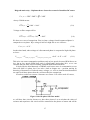
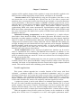
The idea of BLDC motors is to have one phase disconnected, while the current which
runs through the other two phases is controlled. This current causes torque which pulls
rotor. When rotor gets into the right position we should do the switch, that is, we should
disconnect one phase and turn on the one that was disconnected. The current will then
decay through the diode. It resembles a step motor with six steps. If we have three
phases, the steps are: A->B, A->C, B->C, B->A, C->A, C->B – meaning the current goes
from phase A to phase B, from phase A to phase C, etc.(take a look at Fig. 1) The
number of steps will be multiplied by a number of pairs of poles, but that will not have
influence on a control of our motor, and will be neglected at this point, that is we will
assume that motor has one pair of poles (2 poles)
Figure 1-1: Brusshless DC motor functioning
The name BLDC electromotor comes from the similarity of a transfer function of
this motor and a simple DC motor. If we connect our motor to a voltage it will react in
the same manner as a DC motor with independent supplies of armature and stator. In that
analogy permanent magnet plays the role of a stator in DC motor and stator plays a role
of windings. Our digital hardware will do the job of the commutation, one advantage
more we do not have brushes that would have to be changed occasionally.
5
Advantages and drawbacks of BLDC motor control
Hardware & software are more complex than in conventional DC motor control, but
the motor itself is smaller, more efficient, cheaper, lighter, more rugged and reliable. On
the other hand hardware and software are less complex than in regular synchronous
control drives. The fact that we have to control only one current instead of three and still
have, we can say vector control, makes BLDC a very desirable mode of control. We only
need one PWM module – disadvantage is that the mentioned module has to have access
to more pins, in our case six. Generally the processor which is used has less processing
power than the ones used for a regular control of synchronous drives, but at this point we
cannot do much generalization because required processor power depends on a peripheral
hardware: current sensors, position detector etc.
Disadvantage of BLDC control are torque peaks which will occur due to
commutations. These peaks are the consequence of a current decay and can not be
eliminated. I have to say here that for a majority of applications these peaks are
irrelevant. We cannot use brushless DC motor for a position control. In some cases we
can, but it will be poor quality control, as we do not control position continually, our
control is discrete.
At the end of this paragraph I would like to emphasize again, that in the BLDC
control mode we do not have complicated space vector modulation nor multiple current
sensing, that is, we only have to control one current with one PWM module. In spite of it
is simplicity we still have vector control, that is, direct control of the torque.
6
Belgrade university – Diploma theses- Sensorless control of brushless DC motor
2. Position sensing
Types of position sensing
In the machines with permanent magnets on rotor there are various types of
determining rotors position. We can divide them in explicit and implicit. Explicit are the
ones that are mounted on the rotor or inner side of the stator. They include: incremental
indicators (encoders), resolvers and Hall sensors. Implicit sensors extract commutation
information from phase voltages, and can be called sensorless. Probably the best ways of
a position sensing are optical encoders and synchronous resolvers.. They can give us a
very precise position of the rotor, and we can determine very precisely rotors speed by
differentiating their position. These types of position detectors can give us position of
rotor independently of a type of machine. Problems with these types of detectors are their
price and the fact that they have to be mounted on the shaft which complicates the whole
mechanism. In brushless DC motor there is no need for continuous position detection.
We only need to detect position on every 60 degrees, in order to commutate properly.
Low resolution sensors can be used; one optical sensor, for example. We must bear in
mind that dust may cause these sensors not to function. So in BLDC drives, normally, if
we want to control only speed, not position, optical encoders and synchronous resolvers
are not used.
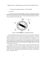
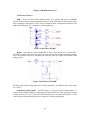
Most frequently used structure for position detection is the set of three Hall
sensors on stator. Principle of their functioning is based on the Hall effect. Current which
runs through the hall element in conjunction with magnetic field which we want to
measure causes potential difference on Hall sensor (due to magnetic force F=qv x B).
Sensors used in brushless DC motor are usually bipolar. On fig. 2-1 is one typical Hall
sensor structure.
Figure 2-1 Position sensing via hall element
Hall element is marked with X – which means that magnetic field is getting into it from
upper side of this paper. Block reg. provides constant current in Hall element. Potential
difference on ends of sensor is fed to an amplifier and than on hysteretic comparator.
When magnetic field is stronger than +threshold output is “1”, and when it is weaker than
7
Chapter 2 Position sensing
–threshold output is “0”. State between thresholds is undefined. Output signals from three
sensors are used as feedback in our control system. Disadvantage of this system is its
sensitivity to PWM. Noise generated by PWM may cause this system to trigger
incorrectly. The main problem here is high cost of Hall sensors and their mounting to the
inner side of stator. That is why we will try to detect rotors position implicitly, without
sensors.
Sensorless position detection
There are various types of position detection. All of them are based on extracting
Figure 2-2 Diagrams of back electromotor forces
8
Belgrade university – Diploma theses- Sensorless control of brushless DC motor
position information from terminal voltages and sometime currents. Position can be
detected through detection of saturation of phase inductance. The stator is saturated by
the magnetic field of the rotor in different axis, depending on the rotor position. The
saturation results in a reduction of the motor winding inductance. The variation of the
inductance can be detected with a high frequency voltage applied to the motor windings.
The resulting high frequency currents are modulated by the varying winding inductance.
If the machine is connected to a pulse width modulated frequency inverter the PWM
frequency works as a carrier frequency for the rotor position detection. This sensorless
method of detecting the rotor position works even in the standstill of the machine, which
as we will see will not be the case of other sensorless methods. Unfortunately this circuit
is quite complex and therefore expensive - in at least two of the three motor phases the
current has to be detected. Using this sensorless detecting on a motor with high power
efficiency will not work correctly, because there is very low saturation in the iron.
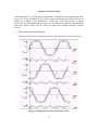
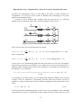
We can detect position of rotor by detecting harmonics of induced motor
voltages. The induced motor voltages show harmonics of odd ordinal number (i=3, 5,
7…), because the flux in the air gap has a rectangular distribution. Figure 2-2 shows
BEM forces broken down to harmonics. As we can see harmonic voltages with ordinal
numbers divisible by three (third harmonic on the picture) create zero phase-sequence
systems, which are not accessible by the connections of three phase conductors. We can
also see that commutation moments coincide with maximal amplitude of third harmonic.
All third harmonics are in the correct phase – they cancel each other out between the
three phase conductors and therefore cannot be detected from the three phases of the
motor in wye connection.
Figure 2-3 System for position derivation from third harmonic
If the wye connection of the motor is accessible, the zero phase-sequence systems can be
detected between this and a virtual wye connection, realized with three resistors. Fig.2-3
shows the corresponding circuit. The voltages are tapped off by potential dividers. The
reference potential of the sensing circuit may be anywhere between the positive or
9
Chapter 2 Position sensing
negative potential of the DC link. Problem with this method is that it cannot operate at
low speeds because BEM forces are weak- this will be problem with other sensorless
methods too. The other problem is that it will not work with motors that have sinusoidaly
distributed windings because there is no third harmonic in BEM forces.
There is a way of detecting commutation points by detecting current slope
variation. When current runs from one phase to another we have:
Vl = 2 RI + 2 L
dI
+ ( E ga − E gb )
dt
(2.1)
, where Vl is a voltage between active phases, as it is shown on the following figure.
Figure 2-4 Two connected phase model
If we assume that terms RI and Vl are constant we can determine zero crossing of BEMF
on a base of term 2L(dI/dt) which is proportional to slope variation. Although this type of
position sensing can provide very precise position detection it requires at least two
current sensors and a DSP with high processing power and fast A/D converters.
The method that will be presented in this paper will be the simplest of all methods.
It is based on analog filtration of phase voltages and their comparison. It will work with
both trapezoidal and sinusoidal BEMF, though this time better with sinusoidal. It will
have some disadvantages also, as we will see in the following chapters.
10
Belgrade university – Diploma theses- Sensorless control of brushless DC motor
3. Sensorless position detection – TVF method
Description
TVF stands for Terminal Voltage Filtration. We will use sensor here (do not let the
name sensorless trick you), but it will be simple circuit attached to the phases of motor. It
will have no mechanical parts, which would be attached to the body of motor, and that is
why we can call it sensorless. This “sensor” can be permanently attached to the drive, so
it can be considered as a part of the drive.
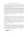
Figure 3-1 Brushless DC motor commutation positions
We want the angle between stator and rotor flux to be closest possible to 90 degrees
– torque is proportional to sin(angle). That is the way to obtain maximum possible torque
with constant current that is maximal electromechanical conversion – maximum
efficiency. On figure 2 we can see motor with rotor in position for commutation. A – F
are axis of possible stator flux. Angle between rotor flux and A axis (which is current
position of rotor flux) is 60 degrees and it is decreasing, and the angle between B and
rotor is 120 degrees, also decreasing getting nearer to ideal 90 degrees. It is obvious that
we should shift stators flux from axis A to axis B in this position. Angle between rotor
and stator flux will always be between 60 to 120 degrees, and that is the best we can gain
with any brushless DC motor.
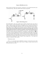
The other way to observe things is to take a look at the electrical model of our
system (Figure 3-2). Current “I” goes from phase A to phase B; In phase C there is no
current. BEM forces Ega, Egb, Egc are pulsating with frequency of rotors turning
multiplied by a number of pair of poles. Gained power of electromechanical conversion is
P=(Ega+Egb)*I. Lets suppose that the commutation that is to be done is from phase B to
phase C. Egc will be increasing in the direction marked on the figure. In one moment it
will become higher than Egb.
11
Chapter 3 Sensorless position detection – TVF method
Figure 3-2 Electrical model of three phase brushless DC motor
That is the moment in which the commutation should be done in order to maintain
the maximum torque. This type of examining is obviously equivalent to the first one
(figure 2) as it will provide the same moments for a commutation.
There is no easy way to measure BEM forces because they are “buried” inside the
motor, but there is a way to determine their values approximately as they are imaged in
phase voltages. In our case from figure 3, shifting of current from phase B to phase C
should occur when Egc becomes higher than Egb. Let us take a look at the phase
voltages.
Vb = Vs − E gb − L *
dI
− R * I , Vc = Vs − E gc
dt
(3.1)
Vs is wye voltage. We can suppose that motor speed is high enough to be Egxm>>R*I,
so we can neglect voltage on the resistor. If we could eliminate voltage on the inductance
we would have Vb’=Vs-Egb - > Vc-Vb=Egb-Egc. This means that one simple analog
comparator could indicate which BEMF is higher.
Figure 3-3 Position detector – first approximation
12
Belgrade university – Diploma theses- Sensorless control of brushless DC motor
As we will see voltage on the inductance can be eliminated by filtering of terminal
voltages. One low pass filter will provide us desired signals. Our system is shown on
figure 3-3. DCS stands for Digital Control System.
Realization
In order to realize described system, we will have to do a brief time and spectral
analysis of phase voltages. Phase that the current is coming from will be referred to as
high side while the other end will be referred to as a low side. We will suppose that PWM
is on the high side of the drive, similar result would be derived for low side. There are
two cases. First one is when voltage that is to be compared with floating voltage
(disconnected phase) is a high side PWM phase, and other when it is constant low side
0V. At this point we will suppose that BEM forces are trapezoidal. It will ease
calculations but the results are similar for sinusoidal BEM forces. We will also suppose
that current is constant, that is neglect current ripple, which is OK while our system is not
in the process of commutation. BEM forces time diagrams are shown on the diagram
(Figure 3-4)
Figure 3-4 BEM forces diagrams
Commutation points will be on crossings of BEM forces as previously defined. In the
time between two commutations, BEM forces are constant on connected phases. On
figure 3-5 we can see diagram of high side voltage.
Figure 3-5: High side voltage diagrams
13
Chapter 3 Sensorless position detection – TVF method
As PWM is applied voltage can be +Edc_bus or zero. Wye voltage Vs has the same as
high side voltage, but half of its amplitude +Edc_bus/2. Voltage of disconnected phase is
Vdp=Vs-Edp, where Edp is BEMF of disconnected phase. We will assume now that
spectral diagram of high side voltage is like the one presented on the following diagram.
Figure 3-6 High side voltage spectral diagram
It has a DC component as we assume that this voltage is slowly changing term and a high
frequency PWM terms. Spectral diagram of disconnected phase voltage will look like
this:
Figure 3-7 Disconnected phase voltage spectral diagram
Voltage on disconnected phase is Vdp=Vhs/2+Edf, so besides the PWM terms we have
low frequency BEMF terms which we can call signal while we will be referring to the
PWM terms as a noise. Term on frequency 3*f1 and higher terms, which are not on the
figure because their value is insignificant, thus will not exist if our motor has sinusoidaly
distributed windings. Now let us take a look at the voltage that we would like to compare
to zero:
Vcmp = Vb − Vc = − RI − L
dI
− E gb + E gc
dt
(3.2)
If we apply analog low pass filter that would cut PWM noise in Vb and Vc we will
eliminate the voltage on inductivity also because it is a high frequency signal, that is,
voltage on the inductivity is equal to zero due to volt second balance. We will neglect
voltage on the resistor as it is very small in comparison to BEMF. Now we have:
14
Belgrade university – Diploma theses- Sensorless control of brushless DC motor
Vcmp = Vb − Vc = − Egb + Egc
(3.3)
Now it is clear that zero crossing of this voltage is the right moment for a commutation.
In previous paragraph we assumed that filter will cut PWM noise and preserve
BEMF signal so one could suppose that one analog first order filter with a pole placed on
the frequency of highest possible BEMF frequency, let us call it Fh. In our system:
Fh =
ω nom
2*π
*p
(3.4)
, where ω is nominal speed, p is number of pairs of poles (not to be mixed with filter
poles). The problem that is neglected is the phase characteristic of our filter. If we place a
pole on frequency Fh it will shift phase of our signal and provoke phase delay, which
would result in delayed commutation that would degrade the performance of our system.
It is well known that phase characteristic starts to bend one decade behind the pole, so
placing a pole on frequency 10*Fh would be desirable. On the other hand, placing a pole
on 10*Fh frequency will decrease rejection.
Figure 3-8 LP filter amplitude characteristic
15
Chapter 3 Sensorless position detection – TVF method
Figure 3-9 LP filter phase characteristic
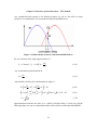
My project decision is to place double pole on frequency 10*Fh. Amplitude and phase
characteristics are shown on the previous figures (Bode approximation). As we can see
from diagrams BEMF components will be completely preserved, and their phase will not
be shifted. In order to analyze PWM noise rejection we will have to adopt PWM
frequency and Fh – highest frequency in BEMF spectrum.
Practical realization
In order to understand the functioning of this system it is best for the reader to take a
look at External signals control mode section at the end of this project (figures of six
states and transition conditions)
In this thesis we will use motor FAST K1 of moog. It is nominal speed is 3000 rpm.,
it has four poles = two pairs which means that our frequency Fh is 100Hz. PWM
frequency used in this work is 5000Hz. Rejection of PWM noise is:
⎛ f
A = −40 * log⎜⎜ PWM
⎝ 10 * Fh
⎞
⎟⎟ = −27.96dB
⎠
(3.5)
This is rejection of the first PWM harmonic, we will neglect existence of higher
harmonics as their rejection is very high (>40dB). We can now calculate ripple of voltage
on filter output. Ripple will be calculated for a duty ratio of 50% because that is the worst
case. Amplitude of the first harmonic of PWM on filter input is:
π
U PWMinput
1
2
= U DC_bus * * ∫ cos(θ )dθ = * U DC_bus
π 0
π
Our rectifier is connected to a regular power grid, so we have:
16
(3.6)
Belgrade university – Diploma theses- Sensorless control of brushless DC motor
U DC_bus = 220V / 240V * 2 < 340V
(3.7)
always. Which means:
max
U PWMinput
=
2
π
* 340V = 216V .
(3.8)
Voltage on filter output will be:
U
max
PWMoutput
=U
max
PWMinput
*10
−
A
20
= 8.6V .
(3.9)
We have two cases of comparison. First is when a voltage from disconnected phase is
compared to zero phase. Wye voltage is half of a high side so we will have:
U PWM_noise = 4.3V .
(3.10)
On the other hand, when voltage of a disconnected phase is compared to high side phase
we have:
U PWM_noise = U PWM_noise_highside − U PWM_noise_disconnecte_phase = 8.6V − 4.3V = 4.3V
(3.11)
This noise can cause commutation problems only at low speeds, because BEM forces are
low, but at low speeds PWM duty ratio is significantly lower than 50%, so we can
conclude that our filter will successfully eliminate undesired PWM noise.
It looks like the third harmonic of BEMF could cause errors in commutation, as our
filter will shift it is phase, but if we take a look at chapter one – position sensing by
detecting of harmonics of induced motor voltages, we will see that the third harmonics
are equal in all three phases thus they will not affect the comparison.
In order to realize our system, a structure on a figure 3-10 will be used. Of course,
Figure 3-10 One phase LP filter model
we will have three circuits, because we have three phases. Let us calculate the values of
resistors and capacitors. Our circuit will be connected to the phases of motor and will be
17
Chapter 3 Sensorless position detection – TVF method
supplied from voltage sources of 5V and 15V, which we have on IRDAK. Ground of
these voltages is common to ground of DC bus. Input voltage can be 380V, and voltage
range on comparator will be 15V because we will be supplying it with 15V DC. That
means:
R1
380
≈
.
R1 + R2 15
(3.12)
We will adopt values R1=27K, R2=680K. These high resistances will provide low
current sink. Voltage that capacitor “sees” is:
RC1sees = R1 || R2 || R3 ≈ R2 || R3
(3.13)
, as R1 has very high value, we can neglect it. If we choose R3 to much bigger than R2,
we could neglect R3, and determine system poles separately due to a principle of poles
separation. Lets say that R3 >> R1 , we have RC1sees = R2 . Now we can determine value of
first capacitor, as we know that poles frequency should be 1000Hz (=10*Fh, Fh=100Hz).
ω p = 2 * π *1000 Hz = 6283.18rad / s , ω p =
=> C1 =
1
RC1sees * C1
1
=5.9nF.
ω p * RC1sees
(3.14)
(3.15)
We will adopt value of 5.6nF, because that is a closest value commercially available,
C1 = 5.6nF .We will adopt R3 = 270 K , ten times bigger than R2 . We choose
C 2 = 680 pF . More accurate value would be 560pF, but since we chose lower value for
C1 , we are taking higher value of C 2 , in order to balance our system. All of this will not
affect significantly characteristic of our filter.
Since comparisons will be executed near ground voltage (half of them), we need to
place one zener diode between ground of our filter and a system ground, to avoid errors
during the comparison. One resistor is placed to provide diode polarization.
Figure 3-11 Zener diode circuit
Rectangle block is a filter from previous figure. Entire circuit is shown on the next page.
18
Belgrade university – Diploma theses- Sensorless control of brushless DC motor
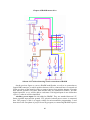
Scheme 3-1 Position detecting circuit
19
Chapter 3 Sensorless position detection – TVF method
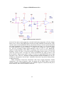
Zener diodes with 15V breakthrough voltage are used for protection. Standard
decoupling capacitor pair is placed between +15V and ground. A capacitor is placed in
parallel with zener diode in order to prevent eventual voltage drops, due to current
variations.
Standard LM339 chip with four comparator blocks is used for voltage comparison.
Comparator outputs are “open collector transistors” which means that we need pull-up
resistors. Pull-up resistors are connected to +5V, as IRDAK will require TTL compatible
levels. We use only three comparators, output of fourth is always logical “1” state, that is,
output transistor is turned off all the time. Besides lowering current sink, we are also
preventing noise generation that could occur due to oscillating of comparators output.
Standard DB9 connector will be used for a connecting of our circuit and IRDAK. On our
circuit side is the male connector because it does not generate voltages, it is completely
passive, it gets its voltages from IRDAK. I have to mention that voltages that come from
IRDAK are not isolated, that is, their potential to earth can be very high, so when
connected to IRDAK our circuit should not be touched!. Circuit inputs (phases) and
outputs are marked with colors. The same are the colors of the wires that are used to
make the circuit. The same are the colors of wires that are used on IRDAK female
connector. All of this is done in order to ease the connection and avoid errors. Color of
phase C input wire is white, I put a brown dash line so we can see it.
Picture 3-1 Position detecting circuit
Signals B>A, C>B, A>C are led to the pins of microcontroller 16F874, and can be
read in any moment by our program. In the following chapters IRDAK drive and
microcontroller will be described. Later we will get into the functioning of our circuit,
software and the whole drive together.
Method TVF phase delay problems
In previous sections, while we were analyzing our circuits function, voltage on
stator serial resistance was neglected, as our assumption was that it is very low, thus will
20
Belgrade university – Diploma theses- Sensorless control of brushless DC motor
not affect the commutation. Here we will analyze the effect of stator resistance on
commutation, we will see in some modes of brushless DC functioning it can cause
significant commutation delay.
In order to do an analysis more complete than the previous ones, we will take
another look at a following figure (there is the same figure in this section…)
Figure 3-12 Electrical model of brushless DC motor
There are two cases, one for each direction of rotation:
1) VCB = VC − VB = L
dI
+ RI + E gb − E gc , V B < VC , we are waiting until VB > VC , and
dt
than we commutate.
2) V AC = V A − V B = L
dI
+ RI + E ga − E gc , V A > VC , we are waiting until VC > V A
dt
In one case we are disconnecting high-side and in the other low side. We will analyze
only the first case because its situation is very similar to the second. As the same filter is
applied on both voltages that are about to be compared, we can apply low pass filter “on
the equation” 1), we will have:
VCB = VC,low_frequency_signal + VC, high_frequency_PWM_noise =V high_frequency_induction_noise+ RI + E gb − E gc
(3.16)
As analyzed in previous section, we can neglect high frequency PWM noise on phase
voltages. Noise on inductivity will actually decrease total noise because its sign is
opposite to a sign of phase noise, and its smaller in amplitude. That means that we can
write:
VC,signal = RI + E gb − Egc
(3.17)
Term RI will cause commutation delay, as there is no way to eliminate it. We could add
some elements in order to compensate for this voltage, but that would make our circuit
21
Chapter 3 Sensorless position detection – TVF method
very complicated and expensive. On following figures we can see the effect of stator
resistance on commutation, for sinusoidal and trapezoidal BEM forces.
Figure 3-12 Phase delay in motor with sinusoidal BEM force
We can calculate delay angle approximately. If
2π ⎞
⎛
E1 = E sin(ωt ) , E 2 = E sin ⎜ ωt −
⎟
3 ⎠
⎝
(3.18)
, one commutation point should be at
ωt =
5π
6
(3.19)
, but term RI will delay the commutation for angle θ :
⎛ ⎛π
⎞
⎛ 5π
⎞⎞
E * ⎜⎜ sin ⎜ + θ ⎟ − sin ⎜ + θ ⎟ ⎟⎟ = RI
⎠
⎝ 6
⎠⎠
⎝ ⎝6
⎛
⎛ 2π ⎞ ⎛ π
⎞⎞
E ⎜⎜ 2 * sin ⎜ −
⎟ cos⎜ + θ ⎟ ⎟⎟ ≅ E * 3 sin θ ≅ 3 * θ * E = RI
⎝ 3 ⎠ ⎝2
⎠⎠
⎝
RI
θ=
3 *E
(3.20)
(3.21)
(3.22)
approximations used here are sin( θ ) ≅ θ , which is all right when θ is near zero. On the
following figure we can see commutation delay effect at motor with trapezoidal BEMF.
22
Belgrade university – Diploma theses- Sensorless control of brushless DC motor
Figure 3-14 Phase delay in motor with trapezoidal BEM force
It is easy to calculate that
θ=
RIπ
6E
(3.23)
which is very similar to the first result. That was expected, since higher harmonics will
not affect significantly the comparison.
In both cases, commutation delay is proportional to a term:
μ=
RI
E
(3.24)
This term will be referred to as a phase distortion coefficient. It should be as lower as
possible. That means that we should keep I low and E high. I is proportional to load
torque, and E is proportional to speed. We conclude that undesired mode of function is at
low speeds with high load torque – elevator applications.
23
Chapter 4 IRADK motor drive
4. IRADK motor drive
Introduction
IRADK is a three phase, variable speed motor drive for appliances and light
industrial applications. It has 230V input in order to be supplied from standard European
power grid. It has optically-isolated RS232 serial link interface to PC. Fault protection for
over-current and over-temperature is provided also. There is a slot for standard 8-bit
microcontroller. Using an adapter we can place a high processing power DSP. Auxiliary
power supplies, 15V and 5V are integrated on IRADK. There is AC input EMI filter,
which eliminates higher harmonics from the input current. On/off switch is placed on the
phase of input voltage.
IRAMS 10UP60A plug and play power module is used as inverter. It is made in
600V NPT IGBT technology. It has current rating of 5A at temperature 100 O C. It has
cross-conduction prevention logic. Reduced Emi is provided by optimized gate drive.
Drive circuit will be analyzed hare part by part. IRADK circuit contains the
following sub circuits:
1.
2.
3.
4.
5.
6.
7.
8.
Power supply
IRAMS power module circuit
Phase current and DC bus voltage sensing circuits
Over current protection
Serial link galvanic isolation circuit
Additional features (LED, button, additional inputs – analog and digital)
28 pin microcontroller slot
Connection strips
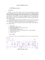
Power supply
High voltage rectifier circuit from IRADK is shown on the following figure.
Figure 4-1 Rectifier circuit
24
Belgrade university – Diploma theses- Sensorless control of brushless DC motor
Variable resistors R45 and R55 serve to limit input current during initialization. That is
when we plug in our IRADK, it has a tendency to drain high current from power grid, as
electrolytic capacitors C37, C42 are completely empty. Capacitors C40 and C41 in
conjunction with EMI inductances block higher harmonics of input current (EMI filter).
Element RV1 serves to limit voltage on its connections, as it will start to conduct thus
will lower the voltage when it gets too high (275V). Capacitor C46 is placed between
ground and zero connection, its purpose is to collect static electricity from our device
case, when ground is accidentally disconnected. Selector S3 is not placed in its position,
that is, it is always in the position on the picture, thus this IRADK can only be used in
Europe. We could place S3 on the board, but as it is highly unlikely that we will use this
circuit both in Europe and United States, and it is very possible that we will destroy
IRADK by toggling the switch accidentally, for that reason we did not put it. Resistors
R51 and R53 are used in order to balance the voltages on electrolytic capacitors, as
tolerance in electrolytic capacitors values is very high ( ± 20% at 120Hz, 20 O C).
On following figures we can see switching power supply which provides us 15V
source.
Figure 4-2 Switcher circuit
Figure 4-3 Internal structure of switching power supply control chip
25
Chapter 4 IRADK motor drive
MOSFET Q2, inductance L1 and diode D13 compose buck converter. It is a very
frequently used structure for lowering the voltage. Purpose of UC3842D chip is to
provide us control of output voltage, through “current mode” control. Internal structure of
the chip is shown in the second figure. Values of capacitance C33 and resistance R33 will
determine the frequency of internal oscillator that is PWM controller frequency. Current
is measured on shunt resistor R41 and fed back to a controlling chip. Resistor-capacitor
pair R39, C36 will filter the information from shunt resistor. Output signal will toggle
on/off our transistor as it will pass to the output voltages on pins 11 and 8 respectively.
We will not need high-side drivers to toggle transistor because entire circuit is “floating”,
that is entire circuit is on the high-side. Circuit power supply is provided through resistors
R30-32. We may wish to supply entire IRADK with lower voltage in that case we will
have to short-circuit one or two of these resistors in order to provide sufficient current.
Circuit on the left side of the control chip serves to provide voltage sensing. When
transistor is off, diodes D8, D9, D12 and D13 conduct the current proving us information
about output voltage. The rest of this circuit filters this information. Compensation is
done by a local feedback through compensation pin 1, it serves to provide stability of our
control loop. D10 and D14 are protection diodes.
Output of our power supply is fed to a 15V linear regulator. Stabilized 15V source
is used as a supply of certain blocks on IRADK as well as input of a 5V linear regulator –
following figure.
Figure 4-4 Stabilizing circuits on IRADK
5V source is used as a microcontroller supply, it also servers as a supply for some blocks.
On the figure we can also see a 3V source. It is made using potential divider and
capacitor, which is fine if we bear in mind low current capacity that will be required of
this source. It will serve us as a reference source for microcontrollers A/D converters as
well as a reference in protection circuit.
26
Belgrade university – Diploma theses- Sensorless control of brushless DC motor
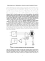
IRAMS10UP60A power module
Utilization of this chip will provide extremely simple and compact solution.
.
Figure 4-5 IRAMS inverter connection on IRADK
It is one modern inverter. It has integrated gate drivers and bootstrap diodes. It has
temperature monitor as well as temperature and over current shutdown. Package is fully
isolated. It has matched propagation delays for all channels, 5V input Schmitt trigger
inputs, cross-conduction prevention logic, isolation up to 2500Vac/min. Inverter power
rating is 0,4KW at input voltage 100-253V. More information can be found on internet
(pdf files related to IRADK 10). On the figure we can see IRAMS connection to IRADK.
Purpose of capacitor C13 and resistor R14 is to delay DC bus voltage appearance, as it
needs to be delayed to the occurrence of 15V voltage, if we want our circuit to function
correctly. Power supply for hi side drivers is ensured through electrolytic capacitors C1,
C5, C11 and their bipolar capacitor pairs. For all phases of inverter, these capacitors are
27
Chapter 4 IRADK motor drive
filled when lower transistor is turned on, so they could supply power when high side
transistor is on – figure (simplified scheme).
Figure 4-6 Simplified functioning of bootstrap diodes in IRAMS
When we turn off lower transistor, diode turns off also, leaving the capacitor with
floating voltage, which can power up a driver circuit. This is the cheapest way to realize
high side power supply. Other types of supply would include transformer for a galvanic
separation, and that is expensive. Disadvantage is that we cannot hold upper transistor
turned on all the time. We have to turn it off in order to refill capacitors. It is
recommended that upper side transistors be off at least 10% of time. That is the reason
why I chose PWM to be on upper transistors – high side. The PWM side transistors will
conduct less time than the ones on the non-PWM side. One might think that this
disadvantage may stop us from holding motors shaft fixed position as we need to have
one upper side transistor turned on all the time, but it is possible. When capacitors gets
empty transistor will turn off, but current from the motor inductance will turn on lowers
IGBT diode, capacitor will refill, also from the inductance current, and upper transistor
will start to conduct again. Of course it will not be conducting all the time.
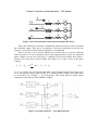
Signals A_HI, B_HI, C_HI, A_LO, B_LO, C_LO are the ones that control states of
transistors in IRAMS. They are TTL compatible, 0-5V, so they can be connected directly
to the pins of microcontroller. They work in negative logic. When one of them is on low
level (0V), target transistor will be turned on, and vice versa. We must take care not to
turn on 2 transistors from the same phase at the same time. That can damage our inverter,
although it has protections – integrated and in our case outside protection also (protection
circuit). We have to take special care while writing software.
ITRIP is the signal from the protection circuit which will be discussed in one of the
next sections. When it is “on” due to a high current, control signals will be ignored and
all transistors will be turned off.
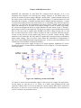
Phase current and DC voltage sensing circuits
In order to provide a high-quality torque and speed control we need to control
current in motor. To control it, we need to measure it. Beside the information about the
current we also need the information about the voltage on DC-link. On the following
28
Belgrade university – Diploma theses- Sensorless control of brushless DC motor
scheme we can see the part of IRADK circuit which is in charge of voltage and current
sensing.
Figure 4-7 Phase current and DC bus voltage measuring circuits
As we can see it leans on the circuit of rectifier from the first section of this chapter.
Voltage measurement is realized on upper part of the image. AN1 presents analog input
of our microcontroller. Voltage on it will be proportional to the voltage of DC bus. For a
DC bus voltage of 385V, voltage on AN1 will be 3V, which is maximum input to A/D
converter as the A/D reference voltage is also 3V. This result is marked with gray color
on the figure. It can be calculated easily as the resistors placed between DC bus, AN1 and
ground are a simple voltage divider. Capacitors serve for noise rejection.
Current sensing problem is more complicated. Circuit dedicated to it is on the lower
part of figure. We are measuring current in DC link Current from electrolytic capacitors
supplies motor through inverter, as well as other parts of IRADK. Assumption is that all
current taken from this source is negligible in comparison to the current that goes to
motor. This is all right because the current that goes to IRADK is “seen” as current that
goes out of DC link multiplied with factor f:
f=
15V
DC _ bus _ voltage
(4.1)
due to switcher function. So we can say that the current which runs through the shunt
resistor R58 is approximately equal to the phase current of the motor. Since we are
working with brushless DC motor, one phase will always be disconnected, so voltage on
shunt resistor will all the time be proportional to the only current that runs in our motor.
29
Chapter 4 IRADK motor drive
When working with other types of motors, currents have to be calculated from this piece
of information only. That can be difficult and sometimes impossible.
Figure 4-8 Switching process
The problem that we have here (which will be problem with other motor types also) is
that we will have current information on shunt resistor only while current runs from one
phase to another through upper transistor. In PWM interval in which upper transistor is
off, current will run through the diode and will not close through shunt resistor (figure).
Shunt signal is fed to a filter that will cut higher frequencies. Its poles are placed at about
1500Hz. That means that PWM component of our signal will be significantly rejected. In
order to measure the current we will have to multiply a value that A/D converter gives us
with PWM duty ratio factor in order to obtain the correct value. This multiplication has to
be done in software and can be problematic. We could use a peak detector to hold the
value that is measured during the first interval of PWM period (when high side transistor
is on, current runs trough the shunt). It would consist of diode and capacitor, and perhaps
operational amplifier. Analog voltage values on AN0 pin of microcontroller obtained by
measuring the current are marked on figure with gray color. They are valid for the case of
current that runs through the shunt resistance long enough that we can neglect the
existence of capacitors on the scheme.
Protection circuit
This is a very important feature of IRADK. Its purpose is to block the inverter when
phase current gets too high. Input in this circuit is voltage on shunt resistor that was
discussed in previous section.
30
Belgrade university – Diploma theses- Sensorless control of brushless DC motor
Figure 4-9 Protection circuit 1/3 (part 1 of 3)
The first part of the circuit is shown on the figure 4-9. In the whole circuit there are four
comparators, chip LM339, the same that I use for a position detecting circuit, only this
one is SMD. In normal functioning mode output of the first comparator will be logical
“1”. Output transistor of the open collector comparator will be turned off. Rising of
current will be followed by falling of voltage on shunt connection (which is the same one
from the previous section). At the current of 10.7A – temporary value, comparator will
change its state. Output transistor turns on. Second comparator in the chain changes its
state (figure below – second part of the circuit, point A is the one from the first part of the
circuit).
31
Chapter 4 IRADK motor drive
Figure 4-10 Protection circuit 2/3
After the first and second comparator, the third and fourth comparator will also change
states (as we will see) and ITRIP signal will become high, IRAMS will shut down. If the
current returns to normal IRAMS will stay shut down, because current overload is latched
on second comparator. If we examine circuit from the last figure, we will see that it has
two stable states due to positive feedback. 1) Output is low {voltage on + pin 5V, voltage
on – pin 3V) 2) Output is high, output transistor is ON {V+=0V, V-=3V}. RESETSC
signal is in high impedance state. When everything is fine, and our circuit is functioning
normally, circuit is in state 1). Current overload will change circuit is state to 2). We can
return our system to state 1) if apply low voltage at RESETSC pin. That is what we will
do in software. When system gets to state 1) we have to return RESETSC pin to high
impedance state, otherwise, current overload protection will be disabled, this must be
avoided, as consequences can be fatal – transistors from active leg can be destroyed due
to high dissipation.
Third comparator inverts the comparison value from second comparator. Fourth
comparator is one form of logical or gate. Its output will set ITRIP signal if occurred
current overload, or if ENABLE signal is zero. ENABLE signal is connected to the pin of
microcontroller, thus can be modified in software.
32
Belgrade university – Diploma theses- Sensorless control of brushless DC motor
Figure 4-11 Protection circuit 3/3
Figure 4-12 Microcontroller input
When current overload occurs or when ENABLE signal changes it state to logical “0”
output transistor of fourth comparator will turn off. ITRIP signal will rise very rapidly,
time constant value is
T=
R50 || R6 * C 25
≅ 160μs
2 *π
(4.2)
approximately. ITRIP will rise until it reaches 5V, because in that moment, protection
diode of input port pin SHORT_CIRCUIT will start to conduct and limit pins voltage to
33
Chapter 4 IRADK motor drive
5V – shown on the second figure. This will happen in about 50 μs from triggering of the
fourth comparator. ITRIP will stay at 5V until ENABLE signal becomes high or until
software reset is applied, depending on what was the cause of ITRIP in the first place.
Diode D18 turns off, C25 starts emptying. After a time interval of something like 200 μs
logical level of ITRIP will be “0”, since time constant in this case is approximately
double than the one in the first case, and exponential streaming to the final voltage, which
s 0V is much slower than in the first case, when it was practically linear. When ITRIP
befalls logical “0”, IRAMS will be operating again. Holdup of 200 microseconds in
IRAMS turn off will grant us additional safety. Transition process can be observed in
software, by reading the value of voltage converted on pit AN2 (figure {}).
RS232 serial link
With intention to connect our IRADK to PC standard RS232 serial link is used.
While IRADK is functioning diverse information will be exchanged between PC and
microcontroller on IRADK. From PC to microcontroller we can transfer speed,
torque/current or voltage/PWM command, as well as any other command, and from
microcontroller to PC we can transfer various bits of information that will allow us to
monitor execution of microcontrollers program and debug. In addition we can observe all
the values that A/D converters have captured: motor current, DC bus voltage etc. Baud
rate of our serial link can go up to 2400 baud/s. This is usually sufficient for the
communication between microcontroller and PC.
The problem that arose here is galvanic isolation of serial link. As we have seen in
previous section, our power supply is not isolated from power grid reference, since we
used buck converter that has no transformer in its structure. Voltage on the ground of
IRADK, the one marked as a ground on all schemes will be hovering between 0 and
something like 300V comparatively to the ground voltage of power grid, while the
ground of
serial link cable is the same as grids. That is why we will have to apply
circuit for signal separation. IRADK solution is application of two opto-transistors, one
for each transfer direction. On the subsequent figure is a part of IRADK circuit
responsible for information transfer between PC and microcontroller.
34
Belgrade university – Diploma theses- Sensorless control of brushless DC motor
Figure 4-13 Serial link galvanic isolation circuit
TxD and RxD are transfer and receive pins of microcontroller, correspondingly. Power to
left part of this circuit is supplied through pins 4 – DTR (Data terminal ready) and 7 –
RTS (Request to send) of RS232 bus. For data signals (the ones we are transmitting and
receiving) the "on" state occurs when the received signal voltage is more negative than -3
volts, while the "off" state occurs for voltages more positive than 3 volts. For control
signals (DTR and RTS in our case) the "on" state occurs when the received signal voltage
is more positive than 3 volts, while the "off" state occurs for voltages more negative than
-3 volts. The voltage between -3 volts and +3 volts is considered to be the transition
region, and the signal state is undefined. DTR signal must be “on” if we want our
communication to function. It is desirable that RTS signal be set to “off”.
Communication will function with RTS set to “on”, but if a cable that connects IRADK
to PC is longer we could have faults, due to noise induced in cable. Values of control
signals are set in PC program responsible for PC-IRADK communication.
I personally used DOS program, written in Borland turbo C because that was the
simplest way to ensure data transfer which in my case was not a problem, considering
low data amount that needed to be transferred. For more advanced use it is
recommendable that we use GUI (graphical user interface) that is provided with IRADK
system.
Our serial communication can work with speeds up to 2400 baud/sec. That is 2400
baud/sec is a highest standard baud rate communication that will function (next one is at
9600). We can have a higher receive rate, but we cannot have higher transmit rate
because of resistor R20 and capacitor C17 which will damage higher frequencies of our
data signal. Problem could be solved by lowering the values of these components, though
they are SMD.
35
Chapter 4 IRADK motor drive
Additional features
LED – There are three light emitting diodes: red, yellow and green on IRADK
which can be used for various signaling purposes. Red could indicate some fault, green
that everything is all right etc. They are in a common anode configuration therefore will
light up when logical “0” is applied to corresponding pin.
Figure 4-14 LED on IRADK
Button – One button is sited on IRADK. It can be very useful as we will see later.
Pressing of button will cause low logical level on related pin, which is normally on high
level. This button needs to be debounced in software, since pin signal will oscillate after
being pressed.
Figure 4-15 Button on IRADK
Working with button in interrupt mode can be unreliable, nevertheless that is the mode
we will use.
Additional analog input – Via this feature we can pass one external signal or a
voltage from variable resistor to analog input of microcontroller. This is done by putting
a drop of tin on a G1 or G2 tin slots. We should not put it at both slots because we can
cause short circuit and damage the device that we are taking signal from.
36
Belgrade university – Diploma theses- Sensorless control of brushless DC motor
Figure 4-16 Strip1
Passing a voltage from variable resistor can be very useful in situations when we want
our IRADK to function without PC command. This could be the way to apply speed
command, for example.
Additional digital inputs (SP1,2 stands for spare input) are shown on the same
figure as analog (above). External digital signal should be TTL compatible. Resistors R43
and zener diodes D15 and D16 are placed with the aim of protection.
Both analog and digital inputs will be passed to microcontroller via strip. Using the
same strip output PWM signals and ITRIP can be transferred to outside of IRADK. This
is useful if we want to observe wave diagrams of this signal on oscilloscope.
High voltage signals strip and power connections
Figure 4-17 High voltage signals strip and power connection
37
Chapter 4 IRADK motor drive
High voltage signals are present on strip2 of IRADK (figure, left image). They can
be passed to various analog circuits that can extract information from them. Our
information will contain rotor position of brushless DC electromotor.
Power connections of IRADK are shown on the figure (right image). Voltage from
the power grid should be connected to the first three pins of CON2. Special care has to be
taken when connecting IRADK to European power grid as its connections are not
polarized that is we cannot tell the difference between phase and neutral connections.
IRADK would function either way but with phase voltage connected to neutral
connection, we would have high voltage on IRADK even when switch is shut down. To
prevent this I suggest that we connect it randomly and than measure voltage between
power grid ground and stabilizer cooler while switch is off. If there is voltage, we should
swap neutral and phase connections.
I should emphasize again that IRADK has no galvanic isolation, hence should not
be touched while in function. This may be problem during the phase of development of
our project. But when project is done (hardware and software) we can place IRADK in a
box which will be connected to the ground thus completely harmless.
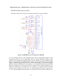
Microcontroller slot on IRADK
IRADK is supposed to work 8-bit microcontroller. On the following figure we can
see slot with microcontroller PIC16C72. We will be using PIC16F873 microcontroller in
this project which is pin compatible to this one. In this section possibilities for connecting
other microcontrollers to IRADK will be considered as well. If we have needs for higher
processing powers we could use DSP that would be connected to IRADK by the use of an
adapter. Task of adapter task would be to bypass required pins of DSP to matching pins
of microcontroller slot.
Figure 4-18 Microcontroller slot on IRADK
38
Belgrade university – Diploma theses- Sensorless control of brushless DC motor
On the figure we can see the microcontroller connections to the circuits from previous
sections. Analog input AN2 is connected to analog signal from ITRIP circuit – take a
look at protection circuit section. Quartz crystal is connected to its corresponding pins in
order to provide oscillating frequency of 20MHz. If we use DSP or some other
microcontroller that is connected to IRADK via adapter it is most probable that it will use
its own oscillator so the structure on the picture is only for PIC16C872 pin compatible
microcontrollers. MCLR – Master clear pin is also only for PIC – when 12V is on it will
be in programming mode, when 5V is on it will be in operating mode. 5V power is
supplied to the slot as its most common power supply for microcontrollers. 3V supply is
used as A/D converter reference, when using non PIC microcontroller this voltage can be
used only for reference functions as its current capacity is very low. All other pins are
connected to input or output ports of PIC thus when using non PIC microcontroller
should be connected to its ports via adapter.
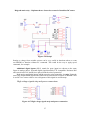
IRADK modifications, position detecting circuit connection
In order to connect position detection circuit we will need three digital inputs. Only
two are available. One of the two available digital inputs is connected to RC1 pin, which
is connected to PWM block, thus will have to be output pin thus can not be input pin.
Since LED are not very important, we will take out two diodes and put two digital input
wires in their place.
39
Chapter 4 IRADK motor drive
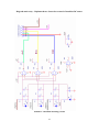
Scheme 4-1 Position detecting circuit connection to IRADK
On the previous figure we can see IRADK modification, as well as its connection to
female DB9 connector, to which position detector will be connected later. Green and red
LEDs are taken of the board in order to connect inputs from position detector (X marks
their anterior location). We chose them because they are connected to PORTC, just like
digital input SP2, so we will be able to read states of all digital inputs in one instruction
cycle (i.e. software will be simplified).
Auxiliary power inputs are also added to IRADK. They are attached between 15V
linear regulator input and the ground. 25V galvanic isolated power source is connected
here. The purpose of this is to supply voltage for microcontroller programming. I used
them also in the first phase of project to test my program, as connecting IRADK to power
40
Belgrade university – Diploma theses- Sensorless control of brushless DC motor
grid voltage can be problematic, an error in software can damage IRADK, while it
probably will not damage it if it is connected to 25V. In addition there is a wire added
that can connect via connector auxiliary input source (25V) directly to DC bus, since we
need a source that will supply motor. This wire has to be disconnected when connecting
IRADK to power grid, in order to avoid short circuit that could cause severe damage to
IRADK.
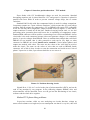
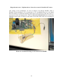
Picture 4-1 Position detecting circuit connected to IRADK
41
Chapter 4 IRADK motor drive
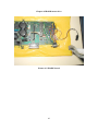
Picture 4-2 IRADK board
42
Belgrade university – Diploma theses- Sensorless control of brushless DC motor
5. PIC16F873 microcontroller
Introduction
PIC16F873 is a 28-Pin 8-Bit CMOS FLASH general purpose microcontroller. It has
4Kb of flash memory. In subsequent sections most important features of PIC will be
discussed. More information can be found on internet, in file:
http://www.microchip.com/download/lit/pline/picmicro/families/16f87x/30292c.pdf
Ports
PIC has three input/output ports: PORTA (6 bit), PORTB (8b) and PORTC (8b).
Every port has some special features adjoined.
PORTA is a six-bit wide, bidirectional port. Pins of this port are passed to the input
of A/D multiplexer Corresponding data direction register is TRISA. Setting a TRISA bit
(= 1) will make the corresponding PORTA pin an input (i.e., put the corresponding
output driver in a Hi-Impedance mode). Clearing a TRISA bit (= 0) will make the
corresponding PORTA pin an output (i.e., put the contents of the output latch on the
selected pin).
Reading the PORTA register reads the status of the pins, whereas writing to it will
write to the port latch. All write operations are read-modify-write operations. Therefore, a
write to a port implies that the port pins are read, the value is modified and then written to
the port data latch. Pin RA4 is multiplexed with the Timer0 module clock input to
become the RA4/T0CKI pin. The RA4/T0CKI pin is a Schmitt Trigger input and an open
drain output. All other PORTA pins have TTL input levels and full CMOS output drivers.
Other PORTA pins are multiplexed with analog inputs and analog VREF input. The
operation of each pin is selected by clearing/setting the control bits in the ADCON1
register (A/D Control Register1). The TRISA register controls the direction of the RA
pins, even when they are being used as analog inputs. The user must ensure the bits in the
TRISA register are maintained set when using them as analog inputs.
PORTB is an 8-bit wide, bi-directional port. The corresponding data direction
register is TRISB. It works the same way as TRISA. Three pins of PORTB are
multiplexed with the Low Voltage Programming function: RB3/ PGM, RB6/PGC and
RB7/PGD. Microcontroller can be programmed with 5V voltage, by using this function.
Furthermore we can program our controller using only boot loader, a small program in
microcontroller memory that would accept data via serial bus and place it in adequate
locations of program memory. Of course boot loader would previously have to be
programmed to microcontroller by a real programmer.
Each of the PORTB pins has a weak internal pull-up. A single control bit can turn
on all the pull-ups. This is performed by clearing bit RBPU of OPTION register.
Four of the PORTB pins, RB7:RB4, have an interrupt-on-change feature. This
interrupt can wake the device from SLEEP.
RB0/INT is an external interrupt input pin and is configured using the INTEDG bit
(OPTION_REG<6>).
43
Chapter 5 PIC16F873 microcontroller
In this project, IRAMS control signals are attached to PORTB (7..2). ENABLE
control signal is attached to RB1. Button is attached to RB0/INT, and it works with
interrupt.
PORTC is an 8-bit wide, bidirectional port. TRISC register functions in the same
manner as TRISB and TRISA. PORTC is multiplexed with several peripheral functions.
PORTC pins have Schmitt Trigger input buffers. When enabling peripheral functions,
care should be taken in defining TRIS bits for each PORTC pin. On the following table
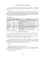
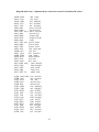
we can see what can be functions of each and every pin.
Table 5-1 PORTC functions
As we can see all communication to the outside world would go through PORTC, since
all communication modules are attached to it. Modes that can be used are: I 2 C, SPI and
USART.
Capture/Compare/PWM functions also use PORTC. In addition we can pass Timer1
clock input to this port as well as make Timer1 oscillator output of it.
In this project we will use some pins of PORTC as digital inputs – from position
detecting circuit. Pins RC6 and RC7 will be used for asynchronous communication with
PC. PWM feature will be used also, but only as a reference, to put it more precisely,
PWM signal will be copied to desired PORTB pin by software.
Timers
Our microcontroller has three programmable timers.
Timer0 timer/counter module can be found in all PIC devices. Interrupt control bits
of this timer are in INTCON register, as it is not considered as peripheral of our
microcontroller. It has the following features:
• 8-bit timer/counter
44
Belgrade university – Diploma theses- Sensorless control of brushless DC motor
• Readable and writable
• 8-bit software programmable prescaler
• Internal or external clock select
• Interrupt on overflow from FFh to 00h
• Edge select for external clock
Timer0 module functioning is defined through OPTION register. Timer mode is
selected by clearing bit T0CS (OPTION_REG<5>). In Timer mode, the Timer0 module
will increment every instruction cycle (without prescaler). If the TMR0 register is
written, the increment is inhibited for the following two instruction cycles. The user can
work around this by writing an adjusted value to the TMR0 register
There is only one prescaler available, which is mutually exclusive shared between
the Timer0 module and the Watchdog Timer. A prescaler assignment for the Timer0
module means that there is no prescaler for the Watchdog Timer, and vice-versa.
Prescaler assignment is defined in PSA (OPTION_REG<5>). If PSA is 0 prescaler is
assigned to the timer0 module, otherwise it is assigned to the watchdog timer. Prescaler
value is defined by three least significant bits of OPTION_REG <PS2..PS0> using the
following table:
Table 5-2 Prescaler value table
Timer0 interrupt control functions via two bits of INTCON register, T0IE – Timer0
interrupt enable, and T0IF – Timer0 interrupt flag. When timer0 wraps over (FFh->00h)
T0IF will be set, in the same moment if T0IE is set interrupt procedure will be called.
T0IF is indication that timer0 interrupt occurred, and should be cleared at the end of
timer0 interrupt procedure.
In this project timer0 will be used a reference time base source of our system.
Timer1 module is a 16-bit timer/counter consisting of two 8-bit registers (TMR1H
and TMR1L), which are readable and writable. The TMR1 Register pair
(TMR1H:TMR1L) increments from 0000h to FFFFh and rolls over to 0000h. Flag pair
TMR1IF (PIR1<0>) and TMR1IE (PIE1<0>) functions in the same manner as timer0
flag pair, only here this flags are bits of peripheral interrupt flag/enable registers
respectively. Timer1 operation is defined by Timer1 control register (t1con).
Timer1 can operate in one of two modes, as a timer and as a counter. The operating
mode is determined by the clock select bit, TMR1CS (T1CON<1>). When in timer
mode, Timer1 increments on every instruction cycle. In counter mode, it increments on
every rising edge of the external clock input. When the Timer1 oscillator is enabled
(T1OSCEN is set), the RC1/T1OSI/CCP2 and RC0/T1OSO/T1CKI pins become inputs.
That is, the TRISC<1:0> value is ignored, and these pins read as ‘0’.
45
Chapter 5 PIC16F873 microcontroller
Bits T1CON<5,4> are prescale bits. By choosing them to be 00, 01, 10, 11, we will
get prescale values 1:1, 1:2, 1:4, and 1:8 correspondingly.
Timer1 can be enabled/disabled by setting/clearing control bit TMR1ON
(T1CON<0>).
In this project Timer1 will be used in accelerating of Brushless DC motor, since
position detecting circuit will not work if rotor is not moving or if it moves slowly.
Timer2 is an 8-bit timer with a prescaler and a postscaler. It can be used as the PWM
time-base for the PWM mode of the CCP module(s). The TMR2 register is readable and
writable, and is cleared on any device RESET. T2CON is the register that determines its
operation. The input clock (FOSC/4) has a prescale option of 1:1, 1:4, or 1:16, selected
by control bits T2CKPS1:T2CKPS0 (T2CON<1:0>). The Timer2 module has an 8-bit
period register, PR2. Timer2 increments from 00h until it matches PR2 and then resets to
00h on the next increment cycle. PR2 is a readable and writable register. The PR2
register is initialized to FFh upon RESET. The match output of TMR2 goes through a 4bit postscaler (which gives a 1:1 to 1:16 scaling inclusive) to generate a TMR2 interrupt
(latched in flag bit TMR2IF, (PIR1<1>)). Timer2 can be shut-off by clearing control bit
TMR2ON (T2CON<2>), to minimize power consumption. Timer2 scheme is revealed on
the following figure.
Figure 5-1 Timer2 block diagram
In this project Timer2 will be used in CAPTURE/COMPARE/PWM module in
order to provide reference PWM signal. Block scheme of mentioned module (when it
functions as PWM) can be seen on subsequent figure. Registers related to this module are
CCP1CON and CCP2CON (2 modules). In Pulse Width Modulation mode, the CCPx pin
(RC2) produces up to a 10-bit resolution PWM output. Since the CCP1 pin is multiplexed
with the PORTC data latch, the TRISC<2> bit must be cleared to make the CCP1 pin an
output. If we want our module to function as PWM, bits <3..2> of CCP1CON register
have to be set. PWM period is defined be PR1 register of Timer2 by formula: PWM
period = [(PR2) + 1] • 4 • TOSC • (TMR2 prescale value).
46
Belgrade university – Diploma theses- Sensorless control of brushless DC motor
Figure 5-2 PWM mechanism
The PWM duty cycle is specified by writing to the CCPR1L register and to the
CCP1CON<5:4> bits. Up to 10-bit resolution is available. The CCPR1L contains the
eight MSbs and the CCP1CON<5:4> contains the two LSbs. This 10-bit value is
represented by CPR1L:CCP1CON<5:4>. The following equation is used to calculate the
PWM duty cycle in time:
PWM duty cycle =(CCPR1L:CCP1CON<5:4>) •TOSC • (TMR2 prescale value)
CCPR1L and CCP1CON<5:4> can be written to at any time, but the duty cycle value is
not latched into CCPR1H until after a match between PR2 and TMR2 occurs (i.e., the
period is complete). In PWM mode, CCPR1H is a read-only register. The CCPR1H
register and a 2-bit internal latch are used to double buffer the PWM duty cycle. This
double buffering is essential for glitch-free PWM operation.
Asynchronous communication module
PIC has integrated USART (Universal synchronous asynchronous receiver
transmitter) module. Here will be discussed aspects of asynchronous communication (full
47
Chapter 5 PIC16F873 microcontroller
duplex), as it is the one used in the project. In addition, it is the most frequently used
form of communication. Full duplex means that both communication entities transmit
data via one line and receive via the other. Data that is being transferred has a ten bit
format. While idle, communication lines are in high state (logical “1”). Device begins
transfer with start bit. This is a bit with logical level “0”. By changing the state of
communication bus, it is “informing” the other device that information is about to be
sent. Then it sends eight data bits – one byte and finishes with stop bit, which is “1” of
course.
Parameters of data transmission are defined in register TXSTA (Transfer status and
control) register. Relevant bits of this register are:
-TX9, nine bit transmit enable bit – enable=1, bit 7
-TXEN, transmit enable bit – enable=1, bit 6
-SYNC, synchronous/asynchronous mode select, synchronous=1, bit
-BRGH, high baud rate select bit, high baud rate=1
-TX9D, value of ninth bit in nine bit communication, can be parity bit
Data reception parameters are located in register RCSTA. Relevant ones are:
-SPEN, Serial Port Enable bit, should be set, bit 7
-RX9, toggles 9/8 bit transfer modes, set for 9 bit communication, bit 6
-CREN, continuous receive enable, bit 4
-ADDEN, Address Detect Enable bit, enable=1, bit 3
-FERR, Framing Error bit, if set, framing error can be updated by reading RCREG
register and receive next valid byte, bit 2
-OERR, Overrun error bit, overrun error=1 (can be cleared by clearing CREN bit), bit 1
-RX9D: 9th bit of Received Data (can be parity bit, but must be calculated by user
firmware), bit 0
Both devices have to be set at the same communication baud rate. Baud rate is
determined by SPBRG register of Baud rate generator. It can be calculated from the
equation: Baud Rate = FOSC/(16(X+1)) if BRGH=1, or Baud Rate = FOSC/(64(X+1)),
if BRGH=0, where BRGH is a bit of transmit status register, X is a value of SPBRG
register (0..255).
Communication registers are RCREG and TXREG. RCREG receives incoming data.
Data that we want to send should be written to TXREG, transfer will start as soon as data
is written.
There are two interrupts that can be adjoined to asynchronous communication:
receive and transmit interrupt. Flag pair that serves receive interrupt is RCIE, RCIF from
registers PIE1 and PIR1 respectively. RCIF is set when byte is received, and is cleared
when RCREG is read.
If we need to send large amount of data, we will use transmit interrupt. Interrupt flag
pair will be TXIE, TXIF from registers PIE1 and PIR1 respectively. TXIF is set when
transfer is over, and can be cleared only by writing new value to TXREG. This will
48
Belgrade university – Diploma theses- Sensorless control of brushless DC motor
maximize our transfer rate, as our software will enable us that new byte is written as soon
as anterior one is sent.
In this project we will use asynchronous communication via receive interrupt.
Interrupt system, interrupt on button press
PIC16F873 has a non-vectored interrupt system. That way, every interrupt that occurs
will cause the execution of the same interrupt procedure. Determining which interrupt
occurred is a task for interrupt procedure. Procedure will poll interrupt flags in order to
determine interrupt cause. Every interrupt has two flags. One for enabling it, and other
which is set whenever interrupt occurs (this one is polled in the procedure), as we have
already seen (timer0 – section 2).
Beside the timer and USART interrupt in this project interrupt from the button is
used also. Button is attached to RB0 bit of PORTB. This interrupt flags are INTE and
INTF (external interrupt). Both are the bits of INTCON register. Interrupt will occur on
rising or falling edge of the signal on RB0 pin, depending of the state of INTEDG flag of
OPTION register.
Microcontroller programming
Programming of PIC microcontroller can be done by a programmer device. In that
case we would place our microcontroller in the programmer, program it, and then get it
out of the programmer and place it in IRADK (or any other device). This technique has
great drawbacks. It takes a lot of time to move microcontroller from one slot to another,
and if we do it many times, it is very probable that we will damage pins of our
microcontroller, which would make it unusable. Solution of these problems can be found
in in-circuit programming, that programming without getting our microcontroller out of
IRADK.
In-circuit programming can be applied by the use of boot loader. It is a small
program that is programmed in high program locations of the microcontroller by a
regular programmer. Afterwards, that program will receive program via serial bus and
place it in microcontroller memory. This is known as programming via change of
configuration. In order to function this programming method, low voltage programming
has to be enabled when programming boot loader, as our microcontroller functions with
5V voltage. There is a PIC downloader program on PC side that is responsible for the
communication with boot loader that is microcontroller. When reset, microcontroller will
wait some time (0.2s for example) to receive program from PIC. If this fails to occur it
will start with execution of program. The disadvantage of this method is use of higher
memory locations of microcontroller, less resources. Besides, it is possible to write
program over a boot loader by mistake. In that case, boot loader would have to be
programmed again, and then we must have the programmer.
The other form of in-circuit programming is to add an adapter to microcontroller slot
on IRADK and place a microcontroller in it. In programming mode we will connect
programmer cable to it and program. In program execution mode we will place one
jumper on a programmer connection. This is the method I used. The only difference is
that I used ICD (In Circuit Debugger) instead of programmer. It is a device that can do
49
Chapter 5 PIC16F873 microcontroller
everything that programmer can do, plus it can be connected via serial bus to
microcontroller, while it is functioning, and then it could read the states of
microcontroller registers, display them on the screen, change them, etc. These features
will not be used in the project.
If we want our ICD to function we have to connect it to pins RB6, RB7, MCLR,
+5V, GND to it. Communication will be realized via serial link through pins RB6 and
RB7. ICD will get a power supply from +5V and ground pins. This voltage will be used
for ICD functioning, as well as for a conversion to 12V via boost converter that is
integrated on ICD. 12V supply is sent back to controller via MCLR pin for programming
purposes. In programming mode RB6, RB7, MCLR pins of microcontroller will be
disconnected from their corresponding pins on IRADK microcontroller slot, while in
functioning mode these pin would connect via jumper.
5V voltage source mentioned in previous paragraph is provided through IRADK
circuitry. 25V voltage source is connected at input of 15V stabilizer. The switcher is
turned off. 25V voltage is supplied from a small isolated transformer. We cannot use
voltage from switcher i.e. power grid, neither from non isolated transformer (auto
transformer, for example), since ICD has its own reference that could be fatal to it.
MPLAB integrated development environment and HI tech C
MPLAB is microchip development environment which is used with all PIC
microcontroller types. It is a user friendly program. It has built in assembler compiler and
linker. Programmer support is also provided, as well as ICD software, so we can program
the chip and debug directly from MPLAB. Program that is written can be simulated in the
simulator. Simulator executes program line by line, while values of registers and other
variables are monitored in watches. External interrupts can be simulated by using a pin
stimulus. Serial communication can not be simulated.
Hi-tech C for PIC programming is user friendly tool that can be added to MPLAB
development environment, so programs can be written and compiled without changing
working environment. Hi-tech C for PIC microcontroller family is completely compatible
with regular ANSI C, from the programming point of view. All statements, commands
and syntax are the same. Even include libraries are the same (they have the same
functions implemented). Since interrupt system is not vectored, that, there is only one
interrupt procedure, we can define only one function that will be interrupt adjoined:
interrupt void isr() {…}. Values of microcontroller registers are accessed by their name,
for example PORTB, TMR1H, etc. To them we can access from any part of program.
This method of programming is very simple, as there is not much new for an engineer to
learn in order to start programming PIC. There are also specialized functions that are
used to modify and read values of microcontroller registers. These functions will enable
more organized program development, but will not affect program function (these
functions are not used in this project). Mathematical operations of multiply, divide, and
even more complicated like log, sin etc. (from math.h include file) should be used
carefully or avoided. Time of their execution can be very long, so they are not suitable for
real time, or any other time critical applications. In this project they are avoided. Majority
of variables that are used in this project are 8 bit variables. There is only one 16 bit
variable. It is natural to use 8 bit variables when working with 8 bit microcontroller.
50
Belgrade university – Diploma theses- Sensorless control of brushless DC motor
Regards on simulation are the same, whether we are using assembler or Hi-tech C. The
difference is only at the beginning of program execution, there is a code inserted by
linker that has to be executed prior to our program.
51
Chapter 6 Sensorless mechanism software resources
6. Sensorless mechanism software resources
Introduction
In chapter 2, position detecting circuit was presented. At the end of the third chapter
circuit connection to IRADK was depicted (IRADK modification section). The theme of
this chapter is software integration of our system. Software resources located on PC will
be described here also (this is referring to serial communication program). There are
several functions that microcontroller software has to implement.
Our motor needs to be accelerated to some speed in order to produce BEM forces
sufficient for position detector functioning. Brushless DC acceleration is achieved though
open loop control, i.e. timer determines commutation moments.
When accelerated, motor should commutate on regular angle intervals, thus signals
from position detecting circuit should be read, and depending of their values
commutation moments should be determined. I can say that this is the most important
software function, although other software functions are indispensable.
Each one of two previously mentioned functions has a mode of functioning that is
adjoined to it. On the following block diagram we can see association of those two
modes. When functioning, our system is always in one of these two modes.
Figure 6-1 Software resources block diagram
52
Belgrade university – Diploma theses- Sensorless control of brushless DC motor
STC stands for State Transition Condition. Blocks on the diagram will be coded in
interrupt service routine and their execution will be invoked by timer interrupt.
Pulse Width Modulation has to be implemented, as our desire is to control values of
phase voltages.
One part of software has to be dedicated to the reset of IRADK. When IRADK signal
ITRIP becomes high, due to high current or on startup, it need to be reset to low level if
we want IRADK to function. This function is implemented on the button press interrupt.
Change of direction of motor rotation is also implemented on button interrupt. When
motor is not blocked (ITRIP=0), button press will cause change of rotation direction,
otherwise it will unblock the motor.
One part of program is in charge of communication with PC, as voltage command
has to be accepted from PC, and current position has to be sent in the other direction in
order to monitor program execution. Microcontroller communicates with PC at the rate of
2400 baud/sec. When byte is received from PC, interrupt will occur.
All previously defined functions are realized in interrupt service routines, except
PWM. It is normal to realize PWM via interrupt, but this is not the case in this project,
since there are some efficiency reasons that will be discussed later. Beside PWM, main
program is also in charge of variable initialization just like in all microcontroller systems.
In this chapter all previously mentioned software functions will be discussed in
subsequent sections, thus program will be analyzed part by part. In appendix A entire
program can be found. But before we get to the analysis of microcontroller program we
will take a brief look at the advantages and drawbacks of C/ASM programming, and also
serial link program on PC side.
Hi-tech C Vs regular PIC assembler programming
It is well known that advantages of comfort program writing in C are followed by
sluggish execution of program, and we know that speed is crucial to real time
applications. In this section we will see that C program execution is sufficiently fast for
this application by comparing one simple program written in C and assembler.
Following program has interrupt routine that toggles the value of Boolean variable
<var> In the main program a value of PORTB bit 0 is toggled (oscillator on RB0). There
are three listings: C code, assembler code produced by program in C and then
independently written assembler code that has the same function.
C program:
#include <pic1687x.h>
interrupt void isr() {
static int var;
if (T0IF)
{if (var) var=0;
53
Chapter 6 Sensorless mechanism software resources
else var=1;
}
T0IF=0;
}
main() {
TRISB=0;
// PORTB is output
OPTION=0X11;
T0IE=1;
GIE=1;
// Global interrupt enable
while (1) if (RB0) RB0=0;
else RB0=1;
};
Compiled C program:
0000 0183 poweru clrf 0x3
0001 3000
movlw 0x0
0002 008A
movwf 0xA
0003 2827
goto exit
0004 00FF intlev movwf 0x7F
0005 0803
movf 0x3,W
0006 0183
clrf 0x3
0007 00A2
movwf 0x22
0008 080A
movf 0xA,W
0009 00A3
movwf 0x23
000A 018A
clrf 0xA
000B 1D0B int_fu btfss 0xB,0x2
000C 280E
goto 0xE
000D 280F
goto 0xF
000E 281D
goto 0x1D
000F 0821
movf 0x21,W
0010 0420
iorwf 0x20,W
0011 1903
btfsc 0x3,0x2
0012 2814
goto 0x14
0013 2815
goto 0x15
0014 2818
goto 0x18
0015 01A0
clrf 0x20
0016 01A1
clrf 0x21
0017 281D
goto 0x1D
0018 1283
bcf 0x3,0x5
0019 1303
bcf 0x3,0x6
001A 01A0
clrf 0x20
54
Belgrade university – Diploma theses- Sensorless control of brushless DC motor
001B 0AA0
incf 0x20
001C 01A1
clrf 0x21
001D 110B
bcf 0xB,0x2
001E 1303
bcf 0x3,0x6
001F 1283
bcf 0x3,0x5
0020 0823
movf 0x23,W
0021 008A
movwf 0xA
0022 0822 int_re movf 0x22,W
0023 0083
movwf 0x3
0024 0EFF
swapf 0x7F
0025 0E7F
swapf 0x7F,W
0026 0009
retfie
0027 3020 exit movlw 0x20
0028 0084
movwf 0x4
0029 3022
movlw 0x22
002A 2031
call clear_ram
002B 0183
clrf 0x3
002C 118A
bcf 0xA,0x3
002D 2FEA
goto main
002E 0604
xorwf 0x4,W
002F 0180
clrf 0x0
0030 0A84
incf 0x4
0031 0604 clear_ xorwf 0x4,W
0032 1D03
btfss 0x3,0x2
0033 282E
goto 0x2E
0034 3400
retlw 0x0
0035 3FFF isr
addlw 0xff
07EA 1683 main bsf 0x3,0x5
07EB 1303
bcf 0x3,0x6
07EC 0186
clrf 0x6
07ED 3011
movlw 0x11
07EE 0081
movwf 0x1
07EF 168B
bsf 0xB,0x5
07F0 178B
bsf 0xB,0x7
07F1 2FFD
goto 0x7FD
07F2 1283
bcf 0x3,0x5
07F3 1303
bcf 0x3,0x6
07F4 1C06
btfss 0x6,0x0
07F5 2FF7
goto 0x7F7
07F6 2FF8
goto 0x7F8
07F7 2FFA
goto 0x7FA
07F8 1006
bcf 0x6,0x0
07F9 2FFD
goto 0x7FD
07FA 1283
bcf 0x3,0x5
07FB 1303
bcf 0x3,0x6
55
Chapter 6 Sensorless mechanism software resources
07FC 1406
07FD 2FF2
07FE 118A
07FF 2827
0800 3FFF
07FC 1406
07FD 2FF2
07FE 118A
bsf 0x6,0x0
goto 0x7F2
bcf 0xA,0x3
goto exit
addlw 0xff
bsf 0x6,0x0
goto 0x7F2
bcf 0xA,0x3
Assembler program:
#include "p16f873.inc"
__CONFIG _CP_OFF & _WDT_OFF & _PWRTE_ON & _XT_OSC
org 0x00
goto Main
org 0x04
goto ISR
Cblock 0x0C
var
w_temp
status_temp
pclath_temp
endc
bank1 macro
bsf STATUS,RP0
endm
bank0 macro
bcf STATUS,RP0
endm
Main
bank1
movlw 0
movwf TRISB
movlw b'00010001'
movwf OPTION_REG
bsf INTCON,T0IE
bsf INTCON,GIE
56
Belgrade university – Diploma theses- Sensorless control of brushless DC motor
bank0
lo btfss PORTB,0
goto loi
bcf PORTB,0
goto lo
loi bsf PORTB,0
goto lo
ISR
movwf w_temp ;
swapf STATUS,w ;
clrf STATUS ;
movwf status_temp ;
movf PCLATH, w ;
movwf pclath_temp ;
clrf PCLATH ;
decfsz var
goto ilo
movlw 0
movwf var
goto ied
ilo movlw 1
movwf var
ied movf pclath_temp, w ;
movwf PCLATH ;
swapf status_temp,w ;
movwf STATUS ;
swapf w_temp,f ;
swapf w_temp,w ;
retfie
end
In the third program (assembler original) the entire context is saved upon entering in
interrupt service routine. C program automatically saves the context. We can see that
program written in C is similar to its assembler equivalent thus in many cases will not
produce holdup in execution. Context saving, as well as some other processes may be
unnecessary, in that case we may choose to write our program in assembler or add some
lines of assembler code in C. In high speed real time systems it is recommendable to
write interrupts in assembler while specific routines called from interrupt can be easily
written in C.
We can insert assembler code lines into C program by using directives #asm and
#endasm:
57
Chapter 6 Sensorless mechanism software resources
#asm
code
#endasm
In code section we can use all variables active in that part of C program. We can also use
predefined variable _RETURN_ to store C function result in it.
Serial link program on PC
Serial communication program on PC side that is used in this project is written in
ansi C. This program will not be listed here as it is unnecessary. This program is adjoined
to this project. It consists of two ansi C files: DOSP.C and DOSF.C (dos is because they
work in dos). In DOSF.C all constants are defined, and usartcomm function is
implemented. DOSP.C is a user of DOSF program. In it we can change parameters of
asynchronous communication: parity bits, baud rate, communication port (COMM1,
COMM2…), etc. Compilation of this program will produce executable program version
that can be transferred to every computer. It is important to have source code of this
program so we can change parameters and recompile it when needed.
When started, this program will automatically write on the screen all values received
from the microcontroller. Write is accomplished by typing a number we want to send to
microcontroller while holding ALT.
This is DOS program, so it may not work in windows NT, and later DOS
independent operating systems. It is the simplest form of PC communication program,
but its performances are sufficient.
Serial link on microcontroller side
Main program initializes serial communication through the following code lines:
TXSTA=0X23; // Serial link configuration
RCSTA=0X90;
SPBRG=129;
RCIE=1;
PEIE=1;
CREN=0;
CREN=1;
(*)
(**)
(***)
(****)
Non-parity, one start, one stop bit, asynchronous, non-addressing communication is the
meaning of first two lines. Communication baud rate is set at 2400 baud/sec (*). Receive
interrupt is enabled (**, ***). Lines (****) clear the OERR flag, that may be set due to
previous overrun error occurrence. Next code lines will enable PWM duty ratio
modification via serial link:
if (RCIF) {
dutyR=RCREG;
58
Belgrade university – Diploma theses- Sensorless control of brushless DC motor
TXREG=dutyR;
CCPR1L=dutyR; }
When a value is received from PC, it is automatically placed in CCPR1L register, echo is
returned to PC. During the program analysis and debug, in some places of program, some
values are sent to PC. All this is accomplished by a simple write to TXREG.
Button press functions
IRADK button is used for two purposes: reset of IRADK over current protection latch
and changing of motor direction. When button is pressed interrupt is generated. Button is
not debounced, so it may happen that one button press causes two interrupts.
Debouncing is avoided because it would use a timer, and would be too complicated, and
as we will see it will not be necessary. Following part of interrupt service routine is
meant to work with button:
if (INTF) {
if (RC4) {temp=TRISC;
TRISC=TRISC & 0xdf;
RC5=1;
TRISC=temp;}
else if (inc) inc=0;else inc=1;
INTF=0;
}
(*)
(**)
(***)
(****)
(*****)
When button is pressed INTF flag is set. Pin RC5 is connected to reset of protection
circuit. Information of this circuit state is on the pin RC4. If over current protection latch
is set RC4 is on high logical level. In order to reset a latch RC5 is made an output, and
logical “1” is placed on it for a short amount of time, roughly 1us (*, **, ***). Then a
circuit is returned to its previous state (****) – RC5 is an input, thus has no effect on
protection circuit functioning. If interrupt occurs more than once, due to fault of
undebounced button, everything will work normally, since there is no big difference if
signal is set at logical “1” 1 or 2 microseconds.
Changing of motor direction is accomplished by changing a value of interrupt service
routine variable <inc>. If a protection latch is not set, than a user must have been pressed
a button because he wants to change a direction of motor rotation. Value of <inc>
variable is complemented (*****). Following section will reveal functioning of our
program with this variable. INTF flag is reset at the end of the procedure for the reason
mentioned in previous chapter. Due to the fault of undebounced button, it may happen
that our motor does not change direction – if interrupt occurs twice or any even number
of times nothing will happen. In that case we should press it again. This poses little
inconvenience. Its solution would be far too complicated, so I decided simply not to solve
it.
Init of this interrupt is done in main() program. Interrupt on rising edge of the RB0
signal is set and enabled. We could work with falling edge, there would be no difference.
59
Chapter 6 Sensorless mechanism software resources
Pulse Width Modulation
Beside PWM this section will deal with toggling on/off of inverter switches
generally. PWM is realized on high side switches of our IRAMS inverter for the reasons
mentioned in previous chapters. There are six states of inverter: 1) C->A 2) B->A 3) B>C 4) A->C 5) A->B 6) C->B. Since there are three phases, A, B and C, letter on the left
side of the arrow is the phase that the current is running into, and a letter on the right side
is the phase that current is running from. Bits 7..2 are in charge of toggling on/off inverter
switches, so a simple write to PORTB will turn on/off desired transistors.
PORTB<7..2>=A#hi, B#hi, C#hi, A#low, B#low, C#low. Pin 1 is ENABLE, “1” should
be written to it. Pin 0 of PORTB is input, thus values that are written to it are ignored.
Every state has two assigned vectors – one for impulse and one for pause of PWM
period. They are defined by following tables:
const unsigned TableOn [7] = {0xff, 0xce, 0xae, 0xba, 0x7a, 0x76, 0xd6};
const unsigned TableOff[7] = {0xff, 0xee, 0xee, 0xfa, 0xfa, 0xf6, 0xf6};
First hexadecimal number in parenthesis is never used, as it has index zero, and there is
no state zero. It is there because an array in C has to start with index zero. Value of state
zero vectors is FF, which guarantee that all switches will be off if this state occurs.
When written to PORTB, value from TableOn will turn on two- switches of inverter,
one on the high side, and one on the low side. Corresponding TableOff vector will turn
off high side switch.
During state change, values of new state vectors are written in variables OnVector
and OffVector:
OnVector=TableOn[state];
OffVector=TableOff[state];
These code lines are repeated two times throughout the program, since there are two
modes of function, thus two modes of state changing. Switch toggling, i.e. PWM, is
realized by consecutive forwarding of On/OffVector values to PORTB.
PWM module of our microcontroller has its output on RC2 pin of PORTC. This
module is used here indirectly. RC2 output is read by software (and only by software),
and then depending of its value, OnVector or OffVector is forwarded to PORTB:
if (RC2) PORTB=OnVector;
else PORTB=OffVector;
These lines should be executed as often as possible in order to have high quality PWM,
especially if impulses are narrow. In our program they are in main(), and in some parts of
interrupt service routine, thus will be executed whenever there is no interrupt, and in
some parts of interrupt procedure. Main program (without initializations) looks like this:
while (1) if (RC2) PORTB=OnVector;
else PORTB=OffVector;
60
Belgrade university – Diploma theses- Sensorless control of brushless DC motor
As we can see main program only executes PWM while waiting for interrupts to occur.
This is not the usual way of PWM realization, but it has some important advantages. The
other way would be to use timer and interrupts, but then we would have to calculate
pause period (or impulse period, if pause is defined). More important, some parts of
interrupt service routine of this project can take a lot of processor time, halting that way
our PWM.
At the end of this section, we are dealing with necessary program fraction,
initialization (PORTB and PWM). PORTB pins 7..1 have to be outputs, and pin 0 input:
TRISB=0X03;
PORTB=0XFF;
TRISB=0X01;
PORTB=0XFC;
These may look complicated as there is a simpler way to initialize PORTB, but it will
provide additional security, as we must not allow two transistors from the same phase to
be turned on. First two lines will ensure that all transistors are off, and ENABLE signal is
an input, thus inverter is out of function. Last two lines will make ENABLE signal an
output on high logical level (i.e. enable).
PWM init is done through the following lines:
TRISC=0XBB;
. . .
PR2=0XFF;
CCPR1L=5;
T2CON=0X05;
CCP1CON=0X0F;
First line configures pins of PORTC, at this point, important is that it configures RC2 to
be an output, otherwise PWM would not function. Lines that follow are not written as
their purpose is not related to PWM (three dots). Lines that follow those lines configure
period register at maximum value (FF=255), and set initial value of PWM impulse at 5 –
it is a low level that will not cause high current protection reaction. PWM impulse width
can be increased/decreased by a data received from serial bus (this will be discussed
later). Last two lines configure a timer2 to work adjoined to PWM module, as well as a
frequency of a clock that drives it. Frequency of a clock is set to 1.25Mh (= Foscillator / 16 ).
One quarter of processor clock is prescaled by a factor 4. PWM frequency is
FPWM = 1.25MHz / 256 = 4882 Hz . Resolution of PWM is 8 bits, two additional PWM
bits (located in CCPRL1 register) are not used.
Motor acceleration mode
As it is already mentioned, motor has to be accelerated to a speed at which BEM
forces will be strong enough that motor position can be extracted from their values. In
order to accelerate motor, commutation moments will be determined by timer. To put it
61
Chapter 6 Sensorless mechanism software resources
briefly, value written in timer register will increase until it reaches maximum. When it
reaches maximum interrupt will occur. Commutation will be executed through interrupt
procedure. Then, new value is written into timer register and so on. Values that will be
written to timer register should increase. That way period of commutation will decrease
and frequency i.e. motor speed will rise.
In this mode of control there is absolutely no feedback, so we will not know the angle
between rotor and stator flu. The idea is to let a high current through motor windings
(higher than nominal), that will produce high electromagnetic torque, which will force
rotor to follow stator field, i.e. angle between stator and rotor flux will be small. High
current and torque guarantee that our motor will move. Current in motor windings will
be: I=U/2R-2E, where U is phase voltage (produced by PWM), R is resistance of one
phase of motor and E is BEMF of one phase of motor. This expression is approximate, as
we neglected existence of inductivity and transient processes, but it is sufficiently precise,
since we do not practically want to control current here – we only want to limit it. In
addition, we can not measure current during the motor startup, since PWM impulses are
very narrow.
Acceleration rate has to be limited. As we know:
M = J *α
M is resultant torque, α is acceleration and J is polar moment of inertia. Resultant torque
is available electromagnetic torque diminished by the value of load torque. If our
acceleration is too high, term on the right side of the equation can get higher than the one
on the left which will cause our motor to block, thus value of acceleration should be
chosen to be reasonable.
In order to implement the acceleration of motor Timer1 timer/counter module is
used. I chose this module because it has two 8 bit registers (tmr1h, tmr1l), when used
with prescaler it can provide longer periods, i.e. lower speeds which are necessary for
acceleration. In addition, resolution is higher, and it is possible to accomplish linear speed
augment more easily. The following portion of software will configure Timer1:
T1CON=0X31; // TMR1 configuring
TMR1IE=1;
First line places hexadecimal value 31 in T1CON register, 0X31=00110001. Bits 7, 6 and
2 are irrelevant. Bits 5 and 4 (11) define prescale value at 1:8 (maximal value). Bit 3
shuts-off oscillator, since we are using internal clock. Bit 1 selects internal clock. Bit 0
enables timer1. Second line of code enables interrupt on timer1. This initialization is
placed in the main procedure, like the most of initializations, though there is a portion of
code in interrupt procedure that will reconfigure this timer when needed. Maximum
period of timer1 configured in manner described above is:
T=
8 * 216
Foscillator / 4
=0.104s (~9.53Hz),
(6.1)
62
Belgrade university – Diploma theses- Sensorless control of brushless DC motor
Frequency of oscillator is 20Mhz. Frequency in parenthesis is the minimal frequency
of state shifting. Divided by 12 it gives us a number of rotations per second – 0.79Hz
(case of 4 pole motor), as we can see it is sufficiently low frequency, that is, speed.
Subsequent block of code is the one in charge of motor acceleration. 16 bit variable
t1Control contains the number that is written to timer1 registers at the end of interrupt
procedure. Increasing of this variable in every cycle (i.e. interrupt occurrence) obviously
accelerates the motor.
interrupt void isr() {
static unsigned state=1;
static unsigned dutyR=0;
static unsigned int tStep=637;
static unsigned int t1Control=0;
static signed direction=1;
static unsigned inc=0;
// Variable definitions;
static unsigned sending=0;
;
. . .
if (TMR1IF)
{state+=direction;
// changing of state
if (state==0) state=6;else if (state>6) state=1; // state overflow ctrl
OnVector=TableOn[state]; //
OffVector=TableOff[state]; //
if (!inc) {t1Control+=tStep;
tStep-=5;}
else {t1Control-=tStep;
tStep+=5;}
if (t1Control<637) {inc=0;
if (direction==1) direction=-1;else direction=1;
tStep=637;
TXREG=100;}
if (t1Control>40000) {OPTION=0X11;
// (**)
T0IE=1;
if (state && 0x01) test=0; else test=1;
if (direction) testVector=testTable1[state];
else testVector=testTable_1[state];
TMR1ON=0;
TMR1IE=0;}
if (tStep<10) tStep=10;
TMR1H=t1Control>>8;
TMR1L=t1Control;
// (***)
// (***)
63
(*)
Chapter 6 Sensorless mechanism software resources
TMR1IF=0;
sending=PORTC & 0x0B;
TXREG=sending;
};
Let us suppose now that we want to move motor that is standing still. Initial value of
variable t1Control is 0, which means that initial speed of our motor will be 0.79 rounds
per second (as discussed above). On every interrupt occurrence state will
increase/decrease (*) depending on the variable direction (+/-1). Motor will start to move
in desired direction.
When the motor is starting to move, interrupts (i.e. state changes) are less frequent,
therefore step should be smaller in order to obtain linear speed augmentation. Current
step value is contained in variable tStep. Now let us take a look at the program presented
above supposing that value of variable inc is zero (inc=0;) and t1Control is less than
40000. As we can see, on every interrupt come to pass following events: state changes in
desired direction, tStep decreases by a fixed value, previous value of t1Control is
increased by tStep value, t1Control is written to timer1 registers (TMR1H, TMR1L).
tStep value is decreased by 5 in every cycle, its initial value is 637. Motor accelerates
until t1Control value reaches 40000. These values (5, 637, 40000) are more or less
empirical, that is, they are the result of testing, not a precise calculation. The calculation
that is used was only approximate, and it only yielded the first results, that I changed later
through experimenting. Though, the motor will not be accelerating ideally linear. In the
following graph we can see the acceleration characteristic.
Figure 6-2 Acceleration characteristic
64
Belgrade university – Diploma theses- Sensorless control of brushless DC motor
Although we do not have linear speed augmentation, this type of acceleration will
preserve a processor time and resources significantly. Any other, more linear type would
have to use one more timer and/or operations like getting a square root, reciprocal value,
multiplication etc., and their execution is very slow.
When t1Control value reaches 40000 our system shifts to the other mode of control –
control by digital input signals. Value of 40000 written to TMR1H: TMR1L register pair
is correlated to motor speed of 2.3 rpm-for a 4 pole motor (4.6 for 2 pole motor). When
motor gets to revolve at this speed, we are changing a control mode. Change of control
mode is done by stopping a timer1 and turning on timer0 (**). More comprehensive
control mode change discussion is in next section.
Variable <inc> serves for a direction change. <inc> is “0” in normal circumstances.
When we press the button <inc> will become “1”, motor will start to slow down
following the same steps that are followed when it was accelerating, i.e. tStep value will
be increasing. When t1Control drops below 637 – maximal step value, direction is
changing, <inc> is back at “0” and motor starts to accelerate again (in opposite direction
of course).
Value from t1Control is written to timer1 registers in two lines (***), since t1Control
is a 16 bit variable – there is an eight bit shift that allows us to write higher byte of
t1Control to TMR1H. Last two lines of code presented in this section are for debugging
purposes, they have no effect on program execution.
External signals control mode
When motor reaches certain speed (anterior section), BEM forces become
significant, as a result position can be detected via position detecting circuit. As it is
discussed in the second chapter, in order to provide high quality torque and speed control,
motor has to be commutated at precise positions. Motor position is reflected in BEM
forces. On subsequent images we can see motor circuit circumstances throughout six
commutation states (states are defined in PWM section of this chapter).
Figure 6-3 State 1 electric model
External signals condition: B>A=1, C>B=1, A>C=0
Transition to state 2 should occur when C>B becomes “0” – positive direction.
65
Chapter 6 Sensorless mechanism software resources
Transition to state 6 should occur when B>A becomes “0” – negative direction.
Figure 6-4 State2 electric model
External signals condition: B>A=1, C>B=0, A>C=0
Transition to state 3 should occur when A>C becomes “1” – positive direction.
Transition to state 1 should occur when C>B becomes “1” – negative direction.
Figure 6-5 State 3 model
External signals condition: B>A=1, C>B=0, A>C=1
Transition to state 4 should occur when B>A becomes “0” – positive direction.
Transition to state 2 should occur when A>C becomes “0” – negative direction.
66
Belgrade university – Diploma theses- Sensorless control of brushless DC motor
Figure 6-6 State 4 model
External signals condition: B>A=0, C>B=0, A>C=1
Transition to state 5 should occur when A>C becomes “1” – positive direction.
Transition to state 3 should occur when C>B becomes “1” – negative direction.
Figure 6-7 State 5 model
External signals condition: B>A=0, C>B=1, A>C=1
Transition to state 6 should occur when A>C becomes “1” – positive direction.
Transition to state 4 should occur when C>B becomes “1” – negative direction.
67
Chapter 6 Sensorless mechanism software resources
Figure 6-8 State 6 model
External signals condition: B>A=0, C>B=1 , A>C=0
Transition to state 1 should occur when B>A becomes “1” – positive direction.
Transition to state 5 should occur when A>C becomes “1” – negative direction.
Position detecting circuit which produces digital signals is discussed in section
Practical realization Summary of external signal values and transition conditions through
states is presented in the following table (6-1, next page). Our program task is to read
external signals (B>A, C>B, A>C) on distinct time intervals, that are much shorter than
duration of one state, and execute state change when a preferred external signal changes
its state. Timer0 is configured to generate interrupts on every ~200us (4882Hz). This
configuration is done upon entering in this control mode – in interrupt procedure of
timer1 (code from previous section, when t1Control variable gets higher than 40000,
marked with (**)). Timer1 oscillator is shut down and timer0 interrupt is enabled,
simultaneously.
STATE
1
2
3
4
5
6
B>A
C>B
A>C
1
1
1
0
0
0
1
0
0
0
1
1
0
0
1
1
1
0
Positive
direction
condition
(C>B)=0
(A>C)=1
(B>A)=0
(C>B)=1
(A>C)=0
(B>A)=1
Negative
direction
condition
(B>A)=0
(C>B)=1
(A>C)=0
(B>A)=1
(C>B)=0
(A>C)=1
Table 6-1 External signals and state transition conditions through states
Next block of code will be executing on timer0 interrupt occurrence.
interrupt void isr() {
. . .
static unsigned test=0;
68
Belgrade university – Diploma theses- Sensorless control of brushless DC motor
static unsigned testVector=0;
static unsigned waitState=3;
static unsigned temp
. . .
if (T0IF)
{if (waitState>0) waitState--;
if (RC2) PORTB=OnVector;
else PORTB=OffVector;
if (waitState==0)
// (*)
if (((testVector & PORTC)!=0 && (test)) ||
// (**)
((testVector & PORTC)==0 && !(test)))
{state+=direction;
// (***)
if (state>6) state=1;else if (state<1) state=6;
OnVector=TableOn[state];
OffVector=TableOff[state];
if (state & 0x01) test=0; else test=1;
//
(****)
if (direction==1) testVector=testTable1[state];else //
(*****)
testVector=testTable_1[state];
waitState=3;
// (******)
}
T0IF=0;
TXREG=state;}
}
External signals A>C, C>B and B>A are connected to PORTC pins 3, 2 and 0
respectively. Their values are determined by a logical AND test. Bits that are to be tested
are determined by a two tables, one for each direction:
const unsigned testTable_1 [7] = {0, 2, 1, 8, 2, 1, 8};
const unsigned testTable1 [7] = {0, 1, 8, 2, 1, 8, 2};
Values 8, 2, 1 correspond to bits RC3, RC1, RC0 (8=00001000 – RC3, 2=00000010 –
RC1, 1=00000001 – RC0). Values 0 from the table are never used. Table testTable1
refers to positive direction of rotation, while testTable_1 refers to negative direction. If
we take a look at the Table 6-1 which summarizes signals that should be tested for every
state, we can notice that it corresponds to a definition of these two tables. During the
commutation adequate value from these tables is placed in variable testVector - code line
(*****).
Variable <test> contains anticipated value of external signal, that is, when external
signal which is monitored becomes equal to test value, commutation should be executed.
Code line (****) calculates the value of test. If state is even test is 0, if state is odd test is
1. This can also be explained by Table 6-1.
Condition check is done by a code line (**). This is the most important code line of
this part of program. One should note that both logical and bitwise AND operations are
69
Chapter 6 Sensorless mechanism software resources
used here. Lines that follow are a commutation execution. Line (***) and following are
the same as for the acceleration mode (previous section). Lines (****) and (*****)
calculate test and testVector values respectively.
Variable waitState is introduced in order to prevent untimely commutation. When a
commutation is executed, it is necessary to wait until a current from the phase that is
detached decays through diode, as external signals may have incorrect values during this
decay. This effect is notable only at low speeds, since BEMF is small and PWM impulse
is narrow. Also, problem exists only if decay is realized through diodes on inverters low
side. If PWM impulses are narrow, we can suppose that the situation is like the one in the
following image.
Figure 6-9 Current decay from disconnected phase
V is voltage in the wye. It is near to zero volts, as BEM forces are low and voltage is zero
on both connected phases (PWM pause). For those reasons, voltage on inductivity will be
low, and current will decay vary slowly. If we analyze decay throughout states, we can
notice that this type of decay will occur in following state transitions: 2->3, 4->5, 6->1
for positive direction, and 3->2, 5->4, 1->6 for negative direction of rotation. This will
cause states 1, 3 and 5 to be skipped at positive direction, and states 2, 4 and 6 at negative
direction. In chapter 3 when filter was presented it was supposed that decay is
instantaneous. This only refers to low speeds and PWM periods (there is a correlation
between these two entities). Variable waitState will solve this problem.
Value of waitState variable determines how many idle cycles after commutation there
should be. Evidently this will cause a limit in maximum speed that we can obtain, as it
will limit the rate of state shifting. In our case this maximum speed will be higher than
nominal, so it is not really a limitation. On every commutation, i.e. state change,
waitState is set to 3 (******). On every next interrupt this value is decreased by 1. Only
when this value reaches 0 (*) our program will start to read external signals and decide
whether or not a commutation should be executed.
I will mention here that when analyzing a filter function in chapter 3, decay is
supposed to be instantaneous. From the point of view of filter analysis this approximation
is fine, considering that current decay time is only a fraction of one state duration time.
At the beginning of this routine we can see two lines that refresh PWM state. These
lines are here in order to prevent harming of PWM quality, since procedure that follows
can take to much time to execute. Last line of code will write a current state number on
PC screen, enabling us to monitor a program execution. Naturally it will not affect a
program execution.
70
Belgrade university – Diploma theses- Sensorless control of brushless DC motor
7. Conclusion
System performance
In order to test the quality of this drive, two brushless motors connected to the same
shaft are used. Both motors are of Italian company moog. First is FAST K2, nominal
speed 3000 rpm, with 2 pair of poles. Second is FAST T1, with 3 pairs of poles, nominal
speed is 4500 rpm. Our drive can work with both motors, though significantly better with
the first one, as BEMF to winding resistance ratio is much higher, for the same load
(chapter 3). While one of these motors is connected to the drive, the other is connected to
variable resistors. By decreasing the resistance we are increasing the load and vice versa.
Loading motor can be connected to one resistor via 3 phase Graz junction. This is much
simpler than using three variable resistors.
When working with a bigger motor (FAST K2), maximum load that it can support
at speeds lower than 2000 rpm is higher than the maximum that we can apply (short
circuit). At this speed BEMF effective value of the other motor is around 38V. When we
apply maximum load at this speed, speed drops to 1660 rpm. One phase current through
short circuit of other motor is 3,8A. Power conversion is:
Pconv = 3 * 3Ω * (3.8 A) 2 =130W.
(7.1)
Three ohms is resistance of one phase. 130W corresponds to loading torque M=0.77Nm
There is a limitation in PWM duty ratio change dynamic. At low speeds PWM
duty ratio has to be changed gradually, otherwise motor will block. This occurs because
sudden rise of PWM impulse causes noise in our system that prevents our position
detection circuit to work properly. As speed gets higher BEM forces rise and this noise
becomes insignificant. Practical results show that the following sequence of duty ratio
command is the most rapid that does not block the rotor: 5, 12, 20, 50,…(of 255). To
those who work with this system this may seem a very serious restriction because the
only way to control PWM duty ratio is by a serial link, and they have to type every single
value from the array (5,6...). But if we have the software that will smartly
increase/decrease duty ratio, this limitation would be practically insignificant. In addition,
this testing is done on very light shaft with practically no inertia. If we had some weight
added to the shaft a rotation would be more stabile and PWM ratio change dynamic
would be more liberated.
Possible system upgrades
Speed control is a logical upgrade to this system. In order to implement speed
control we have to measure speed. Speed measurement will be implemented in software,
as any other type of measurement would be impractical – it would demand mounting of
sensor on the shaft, and all this work is about avoiding that. Speed would be measured by
measuring time between two consecutive state shifts – for lower speeds, or by counting
state shifts in a determined amount of time – for higher speeds. If a precision of speed
measurement is unsatisfying, a software observer can be implemented. PI type of speed
71
Chapter 7 Conclusion
regulator will be applied. Output of this regulator is torque that should be applied to the
shaft. In order to obtain high quality torque control, current has to be controlled.
Current control can be implemented by using one PI regulator, since there is only
one current that we are controlling here. Special care has to be taken a propos state
transition, since current peaks in these time intervals are inevitable. Current measurement
can be problematic, as discussed in chapter 4 (IRADK). Hardware peak detector can be
added in order to obtain current value that is valid during the entire PWM period. Current
measured this way would have a PWM ripple. This problem could be solved by
synchronizing PWM with current measurement. Synchronization usually requires both
PWM and current measurement to have the same timer reference. Hence PWM would
have to be on interrupt, this implies lower quality of PWM. Some hybrid solution would
probably be the best.
Dynamical breaking (recuperation) can be implemented by a simple software
intervention. States should be shifted in the manner that stator flux follows rotor flux.
Practically two tables similar to testTable_1 and testTable1 (previous chapter) should be
added. Two tables for PWM should be added also. While breaking dynamically DC link
voltage has to be measured, since voltage of the link will rise. When DC link voltage gets
too high, breaking has to be halted otherwise link capacitors can be damaged. Dynamical
breaking probably would not have any practical value – in fact it would only serve us if
there is a high inertia on the shaft, but we must bear in mind that its implementation
demands only some software interventions.
Serial communication can be improved. Graphical user interface can be used in
order to communicate more comfort with IRADK microcontroller. In addition we can
assign an address to our microcontroller, so it can serve as a part of a complex system
which is controlled using one central PC. In that case software has to be changed, both on
PC and microcontroller side.
Manual control can be implemented if we want our system to perform simple tasks.
Variable resistor can be placed on IRADK. Voltage from this resistor can be our speed
command. On button we can implement direction control and/or toggle computer/manual
control. This could be useful when validating system functioning.
Possible applications
This system, without upgrades has a transfer function of DC motor with fixed
excitation – permanent magnet. It has no mechanical commutator, and it is a great
advantage because there are no parts that could wear out, there is no speed limit and it is
more ecological – since mechanical commutator usually contains lead that is very hard to
dispose. Brushless DC motors also have better power to volume ratio. It is possible that
in near future brushless DC motors will completely substitute regular DC motors.
A propos our system, it can be used whenever a continual speed change is required.
We can use scalar controlled asynchronous motor as a cheap solution, but if we need
quicker response, this system is superior. Disadvantage is its use in systems that require
frequent direction change, since every direction change implies mode change i.e. time. I
suppose here that we have a simple speed control implemented – without current sensing.
With the upgrades from previous section our system can be considered as a high
quality drive. In this case it is competitive to a drive with regular synchronous motor.
72
Belgrade university – Diploma theses- Sensorless control of brushless DC motor
Brushless DC can not reach the speed of synchronous motor because the gradient of
current slope is higher at the same speed, and it has a problem of current peaks through
commutation, but price of this drive will always be significantly lower. We also must
bear in mind that motor price will be also lower, as sinusoidal distributed winding motors
that are required for a regular drives with synchronous electromotor and they are more
expensive than the ones with linear distribution (i.e. trapezoidal BEMF)
73
Appendixes
Appendix A Source code
#include <pic1687x.h>
unsigned OnVector=0xce;
unsigned OffVector=0xee;
const unsigned TableOn [7] = {0xce, 0xce, 0xae, 0xba, 0x7a, 0x76, 0xd6};
const unsigned TableOff [7] = {0xee, 0xee, 0xee, 0xfa, 0xfa, 0xf6, 0xf6};
const unsigned testTable_1 [7] = {0, 2, 1, 8, 2, 1, 8};
const unsigned testTable1 [7] = {0, 1, 8, 2, 1, 8, 2};
interrupt void isr() {
static unsigned state=1;
static unsigned dutyR=0;
static unsigned int tStep=637;
static unsigned int t1Control=0;
static signed direction=1;
static unsigned inc=0;
static unsigned test=0;
static unsigned testVector=0;
static unsigned waitState=3;
static unsigned sending=0;
static unsigned temp;
if (INTF) {
if (RC4) {temp=TRISC;
TRISC=TRISC & 0xdf;
RC5=1;
TRISC=temp;}
else if (inc) inc=0;else inc=1;
INTF=0;
}
if (RCIF) {
dutyR=RCREG;
TXREG=dutyR;
CCPR1L=dutyR;
}
if (TMR1IF)
{state+=direction;
if (state==0) state=6;else if (state>6) state=1;
OnVector=TableOn[state];
OffVector=TableOff[state];
if (!inc) {t1Control+=tStep;
74
Belgrade university – Diploma theses- Sensorless control of brushless DC motor
tStep-=5;}
else {t1Control-=tStep;
tStep+=5;}
if (t1Control<637) {inc=0;
if (direction==1) direction=-1;else direction=1;
tStep=637;
TXREG=100;}
if (t1Control>55000) {OPTION=0X11;
T0IE=1;
if (state && 0x01) test=0; else test=1;
if (direction) testVector=testTable1[state];
else testVector=testTable_1[state];
TMR1ON=0;
TMR1IE=0;}
if (tStep<10) tStep=10;
TMR1H=t1Control>>8;
TMR1L=t1Control;
TMR1IF=0;
sending=PORTC & 0x0B;
TXREG=sending;
};
if (T0IF)
{
if (waitState>0) waitState--;
if (RC2) PORTB=OnVector;
else PORTB=OffVector;
if (waitState==0)
if (((testVector & PORTC)!=0 && (test)) ||
((testVector & PORTC)==0 && !(test)))
{state+=direction;
if (state>6) state=1;else if (state<1) state=6;
OnVector=TableOn[state];
OffVector=TableOff[state];
if (state & 0x01) test=0; else test=1;
if (direction==1) testVector=testTable1[state];else
testVector=testTable_1[state];
waitState=3;
}
T0IF=0;
TXREG=state;}
75
Appendixes
}
main() {
TRISB=0X03; // PORTB setup
PORTB=0XFF; //
TRISB=0X01; //
PORTB=0XFC; //
TRISC=0XBB; // C register is used for serial communication
T1CON=0X31; // TMR1 configuring
TMR1IE=1;
INTE=1;
// Interrupt enable on button press
TXSTA=0X23; // Serial link configuration
RCSTA=0X90;
SPBRG=129;
RCIE=1;
PEIE=1;
PR2=0XFF;
CCPR1L=5;
T2CON=0X05;
CCP1CON=0X0F;
GIE=1;
//
Global interrupt enable
CREN=0;
CREN=1;
//
OERR reset
while (1) if (RC2) PORTB=OnVector;
else PORTB=OffVector;
};
76
Appendixes
Appendix B Project making and compilation in Hi-tech C for PIC
Every program (i.e. file) written in Hi-tech C for PIC has to adjoined to some project
in order to function. A simple one file project creation and compilation. will be described
here. On Mp-lab menu project we chose the new project. We chose some name for
project – testing, for example. Then we go to edit project option and set a tool HI-TECH,
we also set desired microcontroller type.
Then we should click at testing.hex, when it gets blue (after a click) we should click edit.
Following options should be set:
Language tool: PIC C linker
Info messages: quite (desirable)
Hex format: Intel
Compile for Mp-lab: enabled (checked)
All other options should be unchecked
Then we should return to previous menu and click add node. Testing.c file should be
added (name should match to hex file name) with following settings:
Language tool: PIC C compiler
Generate debug info (desirable)
Floating point: 24 bit
Error file (desirable)
Assembler list – checked
Retain local symbol – checked
Next step - click at Build project (project menu). Errors that occur will be reported in dos
window. If there is no errors object file will be built, and linker will automatically
produce hex file from it. It may occur that linker does not start automatically as compiler
window (One that is finished) needs to be closed manually.
Hex file can be programmed to microcontroller by using programmer. There is enable
programmer option – Pic Start Plus menu. I used ICD instead of programmer. It can do
all that programmer can do and more. In order to program microcontroller with ICD,
development mode has to be changed to ICD (options menu). Upon mode changing ICD
control box will appear. On this box options menu microcontroller and crystal types (xt in
our case) should be set. All other options should be disabled. Program button will
program our microcontroller.
References
[1] Speed controlled single spindle drives for textile machines
http://www.s-line.de/homepages/bosch/sensorless/
[2] PIC 16F87X user manual
http://www.microchip.com/download/lit/pline/picmicro/families/16f87x/302
92c.pdf
[3] Position estimator and simplified control strategy for brushless DC
motors using DSP technology
http://www2.ing.puc.cl/power/paperspdf/dixon/55a.pdf
[4] IRADK 10 Motor drive reference design kit
www.irf.com/technical-info/refdesigns/iradk10.pdf
78
Belgrade university – Diploma theses- Sensorless control of brushless DC motor
Contact
Phone: 011/367-16-07
Cellular phone: 063/587-192
E-mail: [email protected]
E-mail/chat: [email protected]
79