1
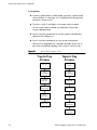
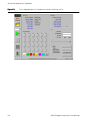
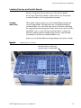
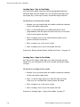
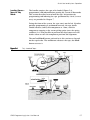
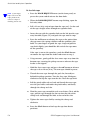
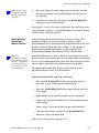
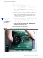
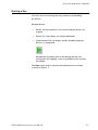
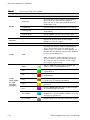
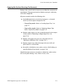
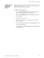
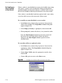
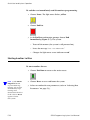
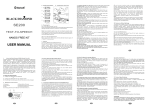
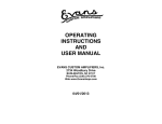
5
A CC E S S L EVE L
1 or higher
Quick Start and
System Operation
This chapter provides instructions to quickly set up and use
the SE200.
Over view
The quick start tasks are as follows (Figure 5-1):
1.
Log onto system (see “To log onto the system” on page 4-8).
2.
Select run parameters.
3.
Load input trays.
4.
Place a reject tray and cover trays.
5.
Load a tape (Tape-to-Tray mode only).
6.
Place master devices into programmer sockets and verify
pin 1 orientation.
7.
Run device lots.
8.
Log off when finished using the system (see “To log off from
the system” on page 4-8).
SE200 Programming System User Manual
5-1
Quick Start and System Operation
Assumptions
■
System is powered on, in Idle mode (paused), and the main
screen (Figure 4-3 on page 4-4) is displayed on the operator
interface (“warm start”)
■
User has a level 1 (or higher) user name and password
(if user name and password are unknown, contact the
system administrator).
■
Level 2 user has previously set up the process information
(discussed in Chapter 6)
■
Level 3 user has previously set up system teach points
(discussed in Appendix D)—should it become necessary to
fine tune teach points during a run, contact a level 3 user
Figure 5-1
Quick Start Process Flow
Tray-to-Tray
Process
Tape-to-Tray
Process
Log on
Log on
Select
Run Parameters
Select
Run Parameters
Load Full
Input Trays
Load Empty
Input Trays
Place Reject
and Cover Trays
Place Reject
and Cover Trays
Place
Master Devices
Load Tape
Run
Device Lots
Place
Master Devices
Run
Device Lots
5-2
SE200 Programming System User Manual
Quick Start and System Operation
Selecting Run Parameters
Use suction
cups appropriate to
device size being
programmed (smaller
than device body
dimensions).
N OT E
After logon, select the parameters for the device lot to be processed.
At this point, the process information should already have been set
up by a level 2 user.
To select Run parameters
1.
Choose Run from the main screen. The Run screen appears
(Figure 5-2), defaulted to the process information used for the
most recent lot run.
2.
Select the process to use. Use the information from the
most recent lot run if it is valid for the current lot, or open
a new process.
To open a new process, select a process from
the Open Process drop-down list, or choose
Open Process to locate and open a process file
(C:\Program Files\Se200\Process\processname.prc).
3.
Enter the lot job number (information representative of the
lot, such as, the job ticket number).
4.
Enter the lot size, then select the appropriate lot type:
– Input—Select this option if it is necessary to process
all devices in the lot (enter the number of devices per
tray, multiplied by the number of trays; for partial
trays, subtract the number of empty pockets)
– Output—Select this option if it is necessary to output
a specific quantity of devices
Leave the Run screen open, and proceed to the next section,
“Loading Input Trays.”
SE200 Programming System User Manual
5-3
Quick Start and System Operation
Figure 5-2
5-4
Enter Appropriate Run Parameters before Starting a Run
SE200 Programming System User Manual
Quick Start and System Operation
Loading Devices and Socket Boards
Devices are input to the system in trays (Tray-to-Tray mode)
or in a tape (Tape-to-Tray mode). Master devices are also placed
in socket boards at the 24 programmer locations.
Loading
Input Trays
The handler requires input trays to be loaded before putting the
system in Run mode. The input elevator is shaped for industrystandard JEDEC trays (the back right corner is beveled, indicating
the expected location of the pin 1 index mark), but can be used for
non-JEDEC trays as well. The input elevator moves a single tray
into the handler, from the bottom of the elevator, and can hold
a maximum of 50 industry-standard JEDEC trays.
Input trays are loaded differently, depending on the process mode.
Figure 5-3
Loading Input Elevator
Beveled corner, indicating
expected pin 1 orientation
SE200 Programming System User Manual
5-5
Quick Start and System Operation
Loading Trays—Tray-to-Tray Mode
For Tray-to-Tray mode, load trays full of unprogrammed devices
onto the input elevator. Empty trays are also placed on top of the
final input tray, at the reject station, and on the output elevator.
To load trays in Tray-to-Tray mode
1.
Remove any trays from inside the handler (within the confines
of the safety doors and panels).
2.
Place a stack of full input trays (filled with devices to be
programmed) onto the input elevator. If the trays are secured
with a band, remove the band.
3.
Place an empty cover tray on top of the final input tray to
protect the devices beneath it.
4.
Place an empty tray at the reject station.
5.
Place an empty cover tray on the output elevator.
Proceed to “Placing Socket Boards and Master Devices” on page 5-9.
Loading Trays—Tape-to-Tray Mode
For Tape-to-Tray mode, load empty trays onto the input elevator.
Empty trays are also placed at the reject station and on the output
elevator.
To load trays in Tape-to-Tray mode
1.
Remove any trays from inside the handler (within the confines
of the safety doors and panels).
2.
Place a stack of empty input trays onto the input elevator.
If the trays are secured with a band, remove the band.
3.
Place an empty tray at the reject station.
4.
Place an empty cover tray on the output elevator.
Proceed to “Loading Tapes—Tape-to-Tray Mode” on page 5-7.
5-6
SE200 Programming System User Manual
Quick Start and System Operation
Loading Tapes—
Tape-to-Tray
Mode
The handler requires the tape to be loaded (Figure 5-4),
programmed, and indexed before putting the system in Run mode.
This section describes how to load the tape. Instructions for
programming and indexing the tape (performed by a level 3 access
user) are provided in Chapter 7.
Facing the front of the system, the tape arm is on the left. If pocket
position programming is performed correctly, the tape feeder
should advance (index) one component at a time, with the
component stopping at the sensor pickup point (over the spring
stabilizer). It is also possible to position the chip camera over the
feeder sensor to view the component position and alignment.
The red and black buttons referred to in this section are located
on the tape feeder. The red button advances the tape; the black
button reverses it.
Figure 5-4
Fully Loaded Tape
SE200 Programming System User Manual
5-7
Quick Start and System Operation
To load the tape
If an empty
tape reel is on the
tape feeder arm,
remove it before
loading a new one.
N OT E
1.
Press the DOOR REQUEST button (on the front panel) to
pause the system and deactivate the door locks.
2.
When the DOOR REQUEST button stops flashing, open the
left safety door.
3.
Pull a 21 cm (8 in) strip of tape from the tape reel. Cut the end
of the tape straight across through one sprocket hole.
4.
Insert the tape with the sprocket hole on the left into the tape
entry location (Figure 5-4) and push the tape until it stops.
5.
Press the red button to advance the tape to the point where
the tape meets the spring stabilizer and the sprockets take
hold. Use your fingers to guide the tape. Stop and pull the
tape back slightly (you should be able to feel the tape move
on the sprocket).
If the tape is not on the sprockets, push the black button
to remove the tape from the feeder and return to step 3.
5-8
6.
Using tweezers, gently pull the clear cover tape away from the
bottom tape, ensuring the pickup sensor to advance the tape
feeder is not tripped.
7.
Hold the clear cover tape and press the red button to advance
the tape at least 16 cm (6 in). The two tapes should separate.
8.
Thread the cover tape through the peel slot, located just
behind the pickup position. Turn the clear tape 90 degrees
clockwise and slip the tape into the slot. Turn the tape back.
9.
Pull the pinch roller release back and thread the cover tape
over the peel roller and under the pinch roller, and finally
through the takeup reel slot.
10.
Wind the cover tape around the reel several times. To tie off the
tape, pull the tape through the slot cut into the side of the
takeup reel and through the hole at the end of the slot.
11.
Tighten the cover tape slack by turning the takeup reel
clockwise.
12.
Press the black button to back up the tape four device
positions.
SE200 Programming System User Manual
Quick Start and System Operation
At this point,
do not use the red
button to advance
the tape.
N OT E
13.
Pass your finger over the pickup sensor to advance the tape
one device position, thus positioning the tape correctly on
the sprocket.
14.
Close the left safety door, then press the DOOR REQUEST
button to activate the door locks.
At this point, a level 3 user must program the tape pocket position
and tape index (Chapter 7). Once programmed, proceed to “Placing
Socket Boards and Master Devices.”
Placing Socket
Boards and
Master Devices
Some socket boards have both master and slave sockets. This
provides the ability to use master devices (known “good”
programmed devices) to download the program directly to the slave
devices. Others may have only slave sockets, as the program is
downloaded from the programmer system computer, into
programming modules (located beneath the socket board).
For
information about
programming master
devices, consult the
provided third-party
programmer system
documentation.
If the socket board has a master socket, manually place the master
devices, in the correct orientation, in each socket to be used for that
lot run. It is recommended to first place the master devices into the
master sockets, then place the socket boards in the handler.
N OT E
The following describes how to place socket boards, based
on whether they have one or two connectors.
To place socket boards with one connector
1.
Press the DOOR REQUEST button (on the front panel) to
pause the system and deactivate the door locks.
2.
When the DOOR REQUEST button stops flashing, open the
safety doors.
3.
Align the metal case into the guiding slot on the module.
4.
Connect the 96-pin DIN connector by pressing down on the
socket board.
Repeat steps 3 and 4 for all other socket board locations.
5.
Close the safety doors, then press the DOOR REQUEST
button to activate the door locks.
Proceed to “Starting a Run” on page 5-11.
SE200 Programming System User Manual
5-9
Quick Start and System Operation
To place socket boards with two connectors
Both ends
of the board
must be pressed
simultaneously
to avoid damaging
the connectors.
N OT E
1.
Press the DOOR REQUEST button (on the front panel) to
pause the system and deactivate the door locks.
2.
When the DOOR REQUEST button stops flashing, open the
safety doors.
3.
Position the metal case of the socket board parallel to the
front panel of the programming module so that the two
female connectors on the board simultaneously connect
to the two male connectors.
4.
Simultaneously press down the top and bottom ends of the
board to connect the 20-pin connectors.
Repeat steps 3 and 4 for all other socket board locations.
5.
Close the safety doors, then press the DOOR REQUEST
button to activate the door locks.
Proceed to “Starting a Run” on page 5-11.
Figure 5-5
5-10
Plugging in a Socket Board with Two Connectors
SE200 Programming System User Manual
Quick Start and System Operation
Starting a Run
Start the run after entering the run parameters and loading
the devices.
To start a run
1.
Ensure all run parameters are entered and the devices are
in place.
2.
Ensure the safety doors are closed and locked.
3.
Choose Start. The run begins and the handler programs
devices, as configured.
Information regarding what to do during the run and
instructions for stopping a run are provided in the sections
that follow.
The Run screen reflects current run information in real-time,
as listed in Table 5-1.
SE200 Programming System User Manual
5-11
Quick Start and System Operation
Table 5-1
Run Screen Real-Time Updates
Option
Parameter
Description
Total Processed
Current number of processed devices in the lot.
Total Yield
Percentage based on the number of programmed
devices in the lot, divided by the number of
processed devices. This value should be between
90 and 100 percent.
Units Passed
Current number of programmed devices in the lot.
Units Rejected
Current number of devices in the lot that failed
programming.
Units Per Hour
Average number of devices processed per hour.
Lot Progress
Current percentage of processed devices in the lot.
Operator
—
Displays the operator name or other unique
identifier, as entered at logon.
Speed
—
Indicates the current system speed (defaults to 100).
Results
Socket
Yield
Percentage based on the number of programmed
devices at this socket in this lot, divided by the
number of processed devices. At the beginning of a
run, this value is 0. During a run, this value should be
between 90 and 100 percent.
Should this value fall below 80% for a
specific socket, consider manually disabling
the socket for the current run, as the socket
may require replacement.
N OT E
Socket
Status Lights
(to right
of Socket
identifier)
5-12
Ready
Indicates white when that socket is enabled and
ready to receive a programmable device.
Pass
Indicates green when the device at that socket
is programmed.
Fail
Indicates red when the device at that socket failed
programming.
Prog
Indicates orange when the device at that socket
is in the process of being programmed.
Empty
Indicates yellow when there is no device in
that socket.
Error
Indicates purple when the device at that socket has
an error that requires attention.
Auto Disable
Indicates blue when that socket is automatically
disabled after a specific number of failures (as set up
in the process parameters).
Oper. Disable
Indicates gray when that socket is manually disabled.
SE200 Programming System User Manual
Quick Start and System Operation
Keeping the System Running Continuously
During a run, several tasks are necessary to allow the system to run
continuously. The operator interface displays messages, indicating
tasks to be completed.
All process modes involve the following tasks:
■
Load additional devices for the lot in progress, as deemed
necessary by the input or output lot size:
– Tray-to-Tray mode—Refer to “Loading Input Trays” on
page 5-5
– Tape-to-Tray mode—Refer to “Replacing Empty Tape
Reels—Tape-to-Tray Mode” on page 5-15
■
Remove empty input trays that cannot be moved to the output
station (refer to “Removing an Empty Input Tray” on
page 5-14)
■
Remove and replace the reject tray when full (refer to
“Replacing a Full Reject Tray” on page 5-14”)
■
Remove output trays when the output elevator is full and
place them in a safe location
■
Re-enable a disabled or error socket (refer to “Re-Enabling an
Auto-Disabled or Error Socket” on page 5-16)
Should it become necessary to replace a failed slave socket or fine
tune teach points during a run, contact a level 3 user.
SE200 Programming System User Manual
5-13
Quick Start and System Operation
Removing an
Empty Input Tray
The system issues the message, “The input tray is empty,” when
it empties an input tray and is unable to move it to the output
station. This occurs when the handler is ready for the next input
tray, but cannot move the tray from the input station because the
tray at the output station is not yet full.
To replace an empty input tray
Replacing a
Full Reject Tray
1.
Press the DOOR REQUEST button (on the front panel) to
pause the system and deactivate the door locks.
2.
When the DOOR REQUEST button stops flashing, open the
right safety door.
3.
Remove the empty tray.
4.
Close the right safety door, then press the DOOR REQUEST
button to activate the door locks.
5.
Choose OK in the Empty Input Tray warning dialog box to
resume processing.
The reject tray requires replacement when the message,
“The reject tray is full,” appears.
To replace a full reject tray
5-14
1.
Press the DOOR REQUEST button (on the front panel) to
pause the system and deactivate the door locks.
2.
Choose Replace Reject Tray.
3.
When the DOOR REQUEST button stops flashing, open the
right safety door.
4.
Remove the full tray and replace it with an empty tray.
Place the full reject tray in a safe location.
5.
Close the right safety door, then press the DOOR REQUEST
button to activate the door locks.
6.
Choose OK in the Full Reject Tray warning dialog box to
resume processing.
SE200 Programming System User Manual
Quick Start and System Operation
Replacing Empty
Tape Reels—
Tape-to-Tray
Mode
When the tape reel is empty, it is necessary to replace it. The system
displays the message, “A vacuum timeout has occurred,” to
indicate the tape reel requires checking.
To replace an empty tape reel
1.
Press the DOOR REQUEST button (on the front panel) to
pause the system and deactivate the door locks.
2.
When the DOOR REQUEST button stops flashing, open the
left safety door.
3.
Remove the empty tape reel.
4.
Load a full tape reel (refer to “Loading Tapes—Tape-to-Tray
Mode” on page 5-7).
5.
Close the left safety door, then press the Door Request button
to activate the door locks.
6.
Choose Retry in the Vacuum Timeout warning dialog box to
resume processing.
SE200 Programming System User Manual
5-15
Quick Start and System Operation
Re-Enabling an
Auto-Disabled
or Error Socket
When a socket is auto disabled or in error, the handler stops using
that socket. A socket can be disabled for failing to program the
specified number of consecutive devices. A socket can be in error
because the handler could not pick the device out of that socket.
If the socket is auto disabled and then replaced with a new socket,
reset the yield to restart the consecutive failure count.
To re-enable an auto-disabled or error socket
1.
In the Run screen, choose the programmer button for the
socket to be enabled. The Programmer Status dialog box
appears (Figure 5-6).
2.
Select Empty or Ready, as appropriate, then choose OK.
3.
When prompted, remove the device, if any, from the socket.
Press the Door Request button to pause the system and
deactivate the safety door locks, remove the device,
then press the Door Request button again to activate
the door locks.
To reset the yield on a replaced socket
1.
In the Run screen, choose the programmer button for the
appropriate socket. The Programmer Status dialog box
appears (Figure 5-6).
2.
Choose Reset Yield, enter the appropriate number, then
choose OK.
3.
Choose OK again to return to the Run screen.
Figure 5-6
5-16
Change the Socket Status or Reset the Yield
SE200 Programming System User Manual
Quick Start and System Operation
Resolving
Warning and
Error Messages
Table 5-2
The following table lists warning messages that can be resolved
by a level 1 user. Additional error messages (which must be resolved
by a level 3 user) are described in Chapter 9.
Operator Interface Warning and Error Messages
Message
Suggestions
Instructions
on Page
Options
The input elevator
is empty.
There are no trays at the input elevator.
Place more trays on the input elevator.
5-5
The input tray is empty.
The input tray is empty and it cannot
be transferred to the output station.
Remove the input tray.
5-14
No tray is present at
the reject station.
Occurs when a lot is started
without a tray at the reject station.
Place an empty tray at the reject station.
5-14
The reject tray is full.
There is no more room for rejected devices
in the reject tray. Remove the reject tray
and replace it with an empty tray.
5-14
A vacuum timeout
has occurred.
Check the following:
• Device is present in the tape reel
• No jam in the tape unit
• Tape alignment
5-7
5-15
Retry
The vision system cannot
locate the device.
Manually remove the problem device.
—
Continue
SE200 Programming System User Manual
OK
5-17
Quick Start and System Operation
Pausing a Run
Pause can be used to temporarily stop the system during a run.
To pause the system
Choose Pause. The light tower flashes yellow.
To continue running the lot after pausing the system
Choose Start. The light tower status indicator changes to green.
5-18
SE200 Programming System User Manual
Quick Start and System Operation
Ending a Lot Run
At the end of a lot, the system moves trays from the input or output
stations to the output elevator. The final device tray contents vary,
depending on whether it is an input or output lot:
Instructions
for emergency stop
are provided in
“Emergency
Procedures” on
page 2-3.
N OT E
■
Input lot—Final tray contains only programmed devices.
■
Output lot—Final tray may contain a combination
of programmed and unprogrammed devices.
This section describes two methods for ending a lot—finish
programming, and end immediately.
To complete the run and finish programming
1.
Choose Pause. The light tower flashes yellow.
2.
Choose End Lot.
3.
At the End Lot confirmation prompt, choose Finish
Programming (Figure 5-7).
The system programs the remaining devices in the slave
sockets and places them in the output tray(s), then:
– Turns off the motors (the system is still powered on).
– Issues the message “Lot is Complete.”
– Changes the light tower status indicator to red.
Figure 5-7
SE200 Programming System User Manual
Choose Appropriate End Lot Option
5-19
Quick Start and System Operation
To end the run immediately and discontinue programming
1.
Choose Pause. The light tower flashes yellow.
2.
Choose End Lot.
3.
At the End Lot confirmation prompt, choose End
Immediately (Figure 5-7). The system:
– Turns off the motors (the system is still powered on).
– Issues the message “Lot was Aborted!”
– Changes the light tower status indicator to red.
Starting Another Lot Run
To start another lot run
If the DOOR
REQUEST button
is pressed during
homing, the system
immediately stops
homing and
deactivates the door
locks. Choose Reset
again to home
the system.
N OT E
5-20
1.
Choose Exit Run to return to the main screen.
2.
Choose Reset to reset and home the system.
3.
Select or confirm the run parameters (refer to “Selecting Run
Parameters” on page 5-3).
SE200 Programming System User Manual