1
Projector
CP-X10000/CP-WX11000/CP-SX12000
User's Manual (detailed) – Operating Guide
Thank you for purchasing this projector.
WARNING ŹBefore using this product, please read the "User's Manual Safety Guide" and related manuals to ensure the proper use of this product.
After reading them, store them in a safe place for future reference.
About this manual
Various symbols are used in this manual. The meanings of these symbols are
described below.
WARNING This entry warns of a risk of serious personal injury or even
death.
CAUTION This entry warns of a risk of personal injury or physical damage.
NOTICE
This entry notices of fear of causing trouble.
Please refer to the pages written following this symbol.
NOTE • The information in this manual is subject to change without notice.
• The manufacturer assumes no responsibility for any errors that may appear in
this manual.
• The reproduction, transfer or copy of all or any part of this document is not
permitted without express written consent.
Trademark acknowledgment
• Windows® is a registered trademark of Microsoft Corporation in the U.S. and/or
other countries.
• VESA and DDC are trademarks of the Video Electronics Standard Association.
• Mac® is a registered trademark of Apple Inc.
• DVI is a trademark of Digital Display Working Group.
• HDMI, the HDMI logo and High-Definition Multimedia Interface are trademarks
or registered trademarks of HDMI Licensing LLC.
• Trademark PJLink is a trademark applied
for trademark rights in Japan, the United
States of America and other countries and areas.
All other trademarks are the properties of their respective owners.
Read this Safety Guide first.
Projector
User's Manual - Safety Guide
Thank you for purchasing this projector.
WARNING • Before using, read these user's manuals of this projector to ensure
correct usage through understanding. After reading, store them in a safe place for
future reference. Incorrect handling of this product could possibly result in personal injury
or physical damage. The manufacturer assumes no responsibility for any damage caused
by mishandling that is beyond normal usage defined in these manuals of this projector.
NOTE • The information in this manual is subject to change without notice.
• The manufacturer assumes no responsibility for any errors that may appear in
this manual.
• The reproduction, transmission or use of this document or contents is not
permitted without express written authority.
About The Symbols
Various symbols are used in this manual, the user’s manual and on the product
itself to ensure correct usage, to prevent danger to the user and others, and to
prevent property damage. The meanings of these symbols are described below.
It is important that you read these descriptions thoroughly and fully understand
the contents.
WARNING
CAUTION
This symbol indicates information that, if ignored, could
possibly result in personal injury or even death due to
incorrect handling.
This symbol indicates information that, if ignored, could
result possibly in personal injury or physical damage
due to incorrect handling.
Typical Symbols
This symbol indicates an additional warning (including cautions). An
illustration is provided to clarify the contents.
This symbol indicates a prohibited action. The contents will be clearly
indicated in an illustration or nearby (the symbol to the left indicates that
disassembly is prohibited).
This symbol indicates a compulsory action. The contents will be clearly
indicated in an illustration or nearby (the symbol to the left indicates that
the power plug should be disconnected from the power outlet).
1
Safety Precautions
WARNING
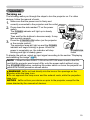
Never use the projector if a problem should occur.
Abnormal operations such as smoke, strange odor, no image, no sound,
excessive sound, damaged casing or elements or cables, penetration of
liquids or foreign matter, etc. can cause a fire or electrical shock.
In such case, immediately turn off the power switch and then disconnect the
power plug from the power outlet. After making sure that the smoke or odor
has stopped, contact your dealer. Never attempt to make repairs yourself
because this could be dangerous.
• The power outlet should be close to the projector and easily accessible.
Disconnect the
plug from the
power outlet.
Use special caution for children and pets.
Incorrect handling could result in fire, electrical shock, injury, burn or vision
problem.
Use special caution in households where children and pets are present.
Do not insert liquids or foreign object.
Penetration of liquids or foreign objects could result in fire or electrical shock.
Use special caution in households where children are present.
If liquids or foreign object should enter the projector, immediately turn off the
power switch, disconnect the power plug from the power outlet and contact
your dealer.
• Do not place the projector near water (ex. a bathroom, a beach, etc.).
• Do not expose the projector to rain or moisture. Do not place the projector
outdoors.
• Do not place flower vases, pots, cups, cosmetics, liquids such as water, etc
on or around the projector.
• Do not place metals, combustibles, etc on or around the projector.
• To avoid penetration of foreign objects, do not put the projector into a case
or bag together with any thing except the accessories of the projector,
signal cables and connectors.
Never disassemble and modify.
The projector contains high voltage components. Modification and/or disassembly of
the projector or accessories could result in fire or electrical shock.
• Never open the cabinet.
• Ask your dealer to repair and clean insider.
Do not give the projector any shock or impact.
If the projector should be shocked and/or broken, it could result in an injury,
and continued use could result in fire or electrical shock.
If the projector is shocked, immediately turn off the power switch, disconnect
the power plug from the power outlet and contact your dealer.
Do not place the projector on an unstable surface.
If the projector should be dropped and/or broken, it could result in an injury,
and continued use could result in fire or electrical shock.
• Do not place the projector on an unstable, slant or vibrant surface such as
a wobbly or inclined stand.
• Use the caster brakes placing the projector on a stand with casters.
• Do not place the projector in the side up position, the lens up position or
the lens down position.
• In the case of a ceiling installation or the like, contact your dealer before
installation.
2
Do not
disassemble.
Safety Precautions (continued)
WARNING
Be cautious of High temperatures of the projector.
High temperatures are generated when the lamp is lit. It could result in fire or
burn. Use special caution in households where children are present.
Do not touch about the lens, air fans and ventilation openings during use or
immediately after use, to prevent a burn. Take care of ventilation.
• Keep a space of 30 cm or more between the sides and other objects such
as walls.
• Do not place the projector on a metallic table or anything weak in heat.
• Do not place anything about the lens, air fans and ventilation openings of
the projector.
• Never block the air fan and ventilation openings.
• Do not cover the projector with a tablecloth, etc.
• Do not place the projector on a carpet or bedding.
Never look through the lens or openings when the lamp is on.
The powerful light could adversely affect vision.
Use special caution in households where children are present.
Use only the correct power cord and the correct power outlet.
Incorrect power supply could result in fire or electrical shock.
• Use only the correct power outlet depending on the indication on the
projector and the safety standard.
• The enclosed power cord must be used depending on the power outlet to
be used.
Be cautious of the power cord connection.
Incorrect connection of the power cord could result in fire or electrical shock.
• Do not touch the power cord with a wet hand.
• Check that the connecting portion of the power cord is clean (with no dust),
before using. Use a soft and dry cloth to clean the power plug.
• Insert the power plug into a power outlet firmly. Avoid using a loose,
unsound outlet or contact failure.
Be sure to connect with ground wire.
Connect the ground terminal of AC inlet of this unit with the ground terminal
provided at the building using the correct power cord; otherwise, fire or
electric shock can result.
• Don’t take the core of power cord away.
Surely connect
the ground wire.
3
Safety Precautions (continued)
WARNING
Be careful in handling the light source lamp.
The projector uses a high-pressure mercury glass lamp made of glass.
The lamp can break with a loud bang, or burn out. When the bulb bursts,
it is possible for shards of glass to fly into the lamp housing, and for gas
containing mercury to escape from the projector’s vent holes.
Please carefully read the section “Lamp”.
Be careful in handling the power cord and external connection
cables.
If you keep using a damaged the power cord or cables, it can cause a fire
or electrical shock. Do not apply too much heat, pressure or tension to the
power cord and cables.
If the power cord or cables is damaged (exposed or broken core wires, etc.),
contact your dealer.
• Do not place the projector or heavy objects on the power cord and cables.
Also, do not place a spread, cover, etc, over them because this could result
in the inadvertent placing of heavy objects on the concealed power cord or
cables.
• Do not pull the power cord and cables. When connecting and
disconnecting the power cord or cables, do it with your hand holding the plug
or connector.
• Do not place the cord near the heater.
• Avoid bending the power cord sharply.
• Do not attempt to work on the power cord.
Be careful in handling the battery of the remote control.
Incorrect handling of the battery could result in fire or personal injury. The
battery may explode if not handled properly.
• Keep the battery away from children and pets. If swallowed consult a
physician immediately for emergency treatment.
• Do not allow the battery in a fire or water.
• Avoid fire or high-temperature environment.
• Do not hold the battery with the metallic tweezers.
• Keep the battery in a dark, cool and dry play.
• Do not short circuit the battery.
• Do not recharge, disassemble or solder the battery.
• Do not give the battery a physical impact.
• Use only the battery specified in the other manual of this projector.
• Make sure the plus and minus terminals are correctly aligned when loading
the battery.
• If you observe a leakage of the battery, wipe out the flower and then
replace the battery. If the flower adheres your body or clothes, rinse well with
water.
• Obey the local laws on disposing the battery.
4
Safety Precautions (continued)
CAUTION
Be careful in moving the projector.
Neglect could result in an injury or damage.
• Do not move the projector during use. Before moving, disconnect the
power cord and all external connections, and close the slide lens door or
attach the lens cap.
• Avoid any impact or shock to the projector.
• Do not drag the projector.
• For moving the projector, use the enclosed case or bag if provided.
Do not put anything on top of the projector.
Placing anything on the projector could result in loss of balance or falling,
and cause an injury or damage. Use special caution in households where
children are present.
Do not attach anything other than specified things to the projector.
Neglect could result in an injury or damage.
• Some projector has a screw thread in a lens part. Do not attach anything
other than specified options (such as conversion lens) to the screw thread.
Avoid a smoky, humid or dusty place.
Placing the projector in a smoke, a highly humid, dusty place, oily soot or
corrosive gas could result in fire or electrical shock.
• Do not place the projector near a smoky, humid or dusty place (ex.
a smoking space, a kitchen, a beach, etc.). Do not place the projector
outdoors.
• Do not use a humidifier near the projector.
Take care of the air filter to normal ventilate.
The air filter should be cleaned periodically. If the air filter becomes clogged
by dust or the like, internal temperature rises and could cause malfunction.
The projector may display the message such as “CHECK THE AIR FLOW”
or turn off the projector, to prevent the internal heat level rising.
• When the indicators or a message prompts you to clean the air filter, clean
the air filter as soon as possible.
• If the soiling will not come off the air filter, or it becomes damaged, replace
the air filter.
• Use the air filter of the specified type only. Please order the air filter
specified in the other manual of this projector to your dealer.
• When you replace the lamp, replace also the air filter. The air filter may be
attached when you buy a replacement lamp for this projector.
• Do not turn on the projector without air filter.
Avoid a high temperature environment.
The heat could have adverse influence on the cabinet of the projector and
other parts. Do not place the projector, the remote control and other parts in
direct sunlight or near a hot object such as heater, etc.
Avoid Magnetism.
Manufacture strongly recommends to avoid any magnetic contact that is not
shielded or protected on or near the projector itself. (ie.,. Magnetic Security
Devices, or other projector accessory that contains magnetic material that has not
been provided by the manufacture etc.) Magnetic objects may cause interruption
of the projector's internal mechanical performance which may interfere with cooling
fans speed or stopping, and may cause the projector to completely shut down.
5
Safety Precautions (continued)
CAUTION
Remove the power cord for complete separation.
• For safety purposes, disconnect the power cord if the projector is not to be
used for prolonged periods of time.
• Before cleaning, turn off and unplug the projector. Neglect could result in
fire or electrical shock.
Disconnect the
plug from the
power outlet.
Ask your dealer to cleaning inside of the projector about every
year.
Accumulations of dust inside the projector cause result in fire or malfunction.
Cleaning inside is more effective if performed before every humid periods
such as rainy season.
• Do not clean inside yourself because it is dangerous.
NOTE
Do not give the remote control any physical impact.
A physical impact could cause damage or malfunction of the remote control.
• Take care not to drop the remote control.
• Do not place the projector or heavy objects on the remote control.
Take care of the lens.
• Close the slide lens door or attach the lens cap to prevent the lens surface being
scratched when the projector is not used.
• Do not touch the lens to prevent fog or dirt of the lens that cause deterioration of display
quality.
• Use commercially available lens tissue to clean the lens (used to clean cameras,
eyeglasses, etc.). Be careful not to scratch the lens with hard objects.
Take care of the cabinet and the remote control.
Incorrect care could have adverse influence such as discoloration, peeling paint, etc.
• Use a soft cloth to clean the cabinet and control panel of the projector and the remote
control. When excessively soiled dilute a neutral detergent in water, wet and wring out the
soft cloth and afterward wipe with a dry soft cloth. Do not use undiluted detergent directly.
• Do not use an aerosol sprays, solvents, volatile substances or abrasive cleaner.
• Before using chemical wipes, be sure to read and observe the instructions.
• Do not allow long-term close contact with rubber or vinyl.
About bright spots or dark spots.
Although bright spots or dark spots may appear on the screen, this is a unique characteristic of
liquid crystal displays, and such do not constitute or imply a machine defect.
Be careful of printing of the LCD panel.
If the projector continues projecting a still image, inactive images or 16:9 aspect images in
case of 4:3 panel, etc., for long time, the LCD panel might possibly be printed.
6
Safety Precautions (continued)
NOTE
About consumables.
Lamp, LCD panels, polarizors and other optical components, and air filter and cooling fans
have a different lifetime in each. These parts may need to be replaced after a long usage
time.
• This product isn’t designed for continuous use of long time. In the case of continuous use
for 6 hours or more, or use for 6 hours or more every day (even if it isn’t continuous), or
repetitious use, the lifetime may be shortened, and these parts may need to be replaced
even if one year has not passed since the beginning of using.
• Any inclining use beyond the adjustment range explained in these user’s manuals may
shorten the lifetimes of the consumables.
Before turning on the power, make the projector cool down adequately.
After turning the projector off, pushing the restart switch or interrupting of the power supply,
make the projector cool down adequately. Operation in a high temperature state of the
projector causes a damage of the electrode and un-lighting of the lamp.
Avoid strong rays.
Any strong ray (such as direct rays of the sun or room lighting) onto the remote control
sensors could invalidate the remote control.
Avoid radio interference.
Any interfering radiation could cause disordered image or noises.
• Avoid radio generator such as a mobile telephone, transceiver, etc. around the projector.
About displaying characteristic.
The display condition of the projector (such as color, contrast, etc.) depends on
characteristic of the screen, because the projector uses a liquid crystal display panel. The
display condition can differ from the display of CRT.
• Do not use a polarized screen. It can cause red image.
Turn the power on/off in right order.
To prevent any trouble, turn on/off the projector in right order mentioned below unless
specifying.
• Power on the projector before the computer or video tape recorder.
• Power off the projector after the computer or video tape recorder.
Take care not to fatigue your eyes.
Rest the eyes periodically.
Set the sound volume at a suitable level to avoid bothering other people.
• It is better to keep the volume level low and close the windows at night to protect the
neighborhood environment.
Connecting with notebook computer
When connecting with notebook computer, set to valid the RGB external image output
(setting CRT display or simultaneous display of LCD and CRT).
Please read instruction manual of the notebook for more information.
7
Lamp
WARNING
HIGH VOLTAGE
HIGH TEMPERATURE
HIGH PRESSURE
The projector uses a high-pressure mercury glass lamp. The lamp can break with a
loud bang, or burn out, if jolted or scratched, handled while hot, or worn over time.
Note that each lamp has a different lifetime, and some may burst or burn out soon after
you start using them. In addition, when the bulb bursts, it is possible for shards of
glass to fly into the lamp housing, and for gas containing mercury to escape from the
projector’s vent holes.
About disposal of a lamp • This product contains a mercury lamp; do not put in trash.
Dispose of in accord with environmental laws.
For lamp recycling, go to www.lamprecycle.org. (in USA)
For product disposal, contact your local government agency or www.eiae.org (in the US)
or www.epsc.ca (in Canada).
For more information, call your dealer.
Disconnect
the plug from
the power
outlet
• If the lamp should break (it will make a loud bang when it does), unplug
the power cord from the outlet, and make sure to request a replacement
lamp from your local dealer. Note that shards of glass could damage the
projector’s internals, or cause injury during handling, so please do not try to
clean the projector or replace the lamp yourself.
• If the lamp should break (it will make a loud bang when it does), ventilate
the room well, and make sure not to breathe the gas that comes out of the
projector vents, or get it in your eyes or mouth.
• Before replacing the lamp, make sure the power switch is off and the
power cable is not plugged in, then wait at least 45 minutes for the lamp to
cool sufficiently. Handling the lamp while hot can cause burns, as well as
damaging the lamp.
• Do not open the lamp cover while the projector is suspended from above.
This is dangerous, since if the lamp’s bulb has broken, the shards will
fall out when the cover is opened. In addition, working in high places is
dangerous, so ask your local dealer to have the lamp replaced even if the
bulb is not broken.
• Do not use the projector with the lamp cover removed. At the lamp
replacing, make sure that the screws are screwed in firmly. Loose screws
could result in damage or injury.
• Use the lamp of the specified type only.
• If the lamp breaks soon after the first time it is used, it is possible that
there are electrical problems elsewhere besides the lamp. If this happens,
contact your local dealer or a service representative.
• Handle with care: jolting or scratching could cause the lamp bulb to burst
during use.
• Using the lamp for long periods of time, could cause it dark, not to light up
or to burst. When the pictures appear dark, or when the color tone is poor,
please replace the lamp as soon as possible. Do not use old (used) lamps;
this is a cause of breakage.
8
Regulatory Notices
FCC Statement Warning
This device complies with part 15 of the FCC Rules. Operation is subject to the following
two conditions: (1) This device may not cause harmful interference, and (2) this device
must accept any interference received, including interference that may cause undesired
operation.
WARNING: This equipment has been tested and found to comply with the limits for a
Class B digital device, pursuant to Part 15 of the FCC Rules. These limits are designed
to provide reasonable protection against harmful interference in a residential installation.
This equipment generates, uses, and can radiate radio frequency energy and, if not
installed and used in accordance with the instructions, may cause harmful interference
to radio communications. However, there is no guarantee that interference will not occur
in a particular installation. If this equipment does cause harmful interference to radio
or television reception, which can be determined by turning the equipment off and on,
the user is encouraged to try to correct the interference by one or more of the following
measures:
- Reorient or relocate the receiving antenna.
- Increase the separation between the equipment and receiver.
- Connect the equipment into an outlet on a circuit different from that to which the receiver
is connected.
- Consult the dealer or an experienced radio/TV technician for help.
INSTRUCTIONS TO USERS: This equipment complies with the requirements of FCC
(Federal Communication Commission) equipment provided that the following conditions
are met. Some cables have to be used with the core set. Use the accessory cable or a
designated-type cable for the connection. For cables that have a core only at one end,
connect the core to the projector.
CAUTION: Changes or modifications not expressly approved by the party responsible for
compliance could void the user’s authority to operate the equipment.
For the Customers in CANADA
NOTICE: This Class B digital apparatus complies with Canadian ICES-003.
Warranty And After-Service
Unless seen any abnormal operations (mentioned with the first paragraph of
WARNING in this manual), when a problem occurs with the equipment, first refer to the
“Troubleshooting” section of the “Operating Guide”, and run through the suggested checks.
If this does not resolve the problem contact your dealer or service company. They will tell
you what warranty condition is applied.
9
Contents
Contents
About this manual . . . . . . . . . . . 1
Contents . . . . . . . . . . . . . . . . . . 2
Introduction . . . . . . . . . . . . . . . 3
Projector features . . . . . . . . . . . . . . . 3
Important safety instruction (for the
moving) . . . . . . . . . . . . . . . . . . . . . . . 3
Checking the contents of package . . 4
Attaching the lens unit. . . . . . . . . . . . 4
Part names . . . . . . . . . . . . . . . . 5
Projector . . . . . . . . . . . . . . . . . . . . . . 5
Control panel. . . . . . . . . . . . . . . . . . . 6
Indicator lamp . . . . . . . . . . . . . . . . . . 6
Rear panel . . . . . . . . . . . . . . . . . . . . 6
Remote control . . . . . . . . . . . . . . . . . 7
Setting up . . . . . . . . . . . . . . . . . 8
Installation environment . . . . . . . . . . 8
Projection style . . . . . . . . . . . . . . . . . 8
Projection distance . . . . . . . . . . . . . . 9
Placement . . . . . . . . . . . . . . . . . . . . 10
Supplementary anti-theft means . . . 10
Connecting with your devices . . . . . 11
Connecting power supply . . . . . . . . 15
Remote control . . . . . . . . . . . . 16
Putting batteries . . . . . . . . . . . . . . . 16
Transmitting condition . . . . . . . . . . . 17
Changing the frequency of remote
control signal . . . . . . . . . . . . . . . . . . 17
Using the REMOTE ID function . . . 18
Using as a wired remote control . . . 18
Laser pointer . . . . . . . . . . . . . . . . . . 18
Operating . . . . . . . . . . . . . . . . 19
Turning on . . . . . . . . . . . . . . . . . . . . 19
Turning off . . . . . . . . . . . . . . . . . . . . 20
Using the elevator feet . . . . . . . . . . 20
Using the functions for the lens. . . . 21
Displaying and switching the image 22
Selecting an aspect ratio. . . . . . . . . 23
Using the automatic adjustment feature . . 23
Adjusting the position . . . . . . . . . . . 24
Correcting the keystone distortion . . . 24
Using the magnify feature . . . . . . . . 25
Temporarily freezing the screen . . . 25
Temporarily blanking the screen . . . 26
Temporarily shutting the screen . . . 26
P by P (Picture by Picture) . . . . . . . 27
Using the menu function . . . . . . . . 28
2
EASY MENU. . . . . . . . . . . . . . . 29
ASPECT, AUTO KEYSTONE,
KEYSTONE,
KEYSTONE, PICTURE MODE, ECO MODE,
MIRROR, RESET, FILTER TIME, LANGUAGE,
ADVANCED MENU, EXIT
PICTURE menu . . . . . . . . . . . . 31
BRIGHTNESS, CONTRAST, GAMMA, COLOR TEMP,
COLOR, TINT, SHARPNESS, ACTIVE IRIS, MY MEMORY
IMAGE menu . . . . . . . . . . . . . . 34
ASPECT, OVER SCAN, V POSITION, H POSITION,
H PHASE, H SIZE, AUTO ADJUST EXECUTE
INPUT menu . . . . . . . . . . . . . . 36
PROGRESSIVE, VIDEO NR, 3D-YCS, COLOR
SPACE, COMPONENT, VIDEO FORMAT, DIGITAL
FOMAT, DIGITAL RANGE, COMPUTER IN, FRAME
LOCK, RESOLUTION
SETUP menu . . . . . . . . . . . . . . 40
AUTO KEYSTONE,
KEYSTONE,
KEYSTONE,
ECO MODE, MIRROR, MONITOR OUT
SCREEN menu . . . . . . . . . . . . . 42
LANGUAGE, MENU POSITION, BLANK, START UP,
MyScreen, MyScreen Lock, MESSAGE, SOURCE
NAME,TEMPLATE, C.C.
OPTION menu . . . . . . . . . . . . . 47
SOURCE SKIP, AUTO SEARCH, AUTO KEYSTONE,
DIRECT ON, AUTO OFF, SUTTER TIMER LAMP
TIME, FILTER TIME, MY BUTTON, MY SOURCE,
SERVICE
NETWORK menu . . . . . . . . . . . 56
SETUP, PROJECTOR NAME, MY IMAGE,
INFORMATION, SERVICE
SECURITY menu . . . . . . . . . . . 61
ENTER PASSWORD, SECURITY PASSWORD,
MyScreen PASSWORD, PIN LOCK, TRANSITION
DETECTOR, MY TEXT PASSWORD, MY TEXT
DISPLAY, MY TEXT WRITING
Maintenance . . . . . . . . . . . . . . 67
Lamp unit . . . . . . . . . . . . . . . . . . . . 67
Filter unit . . . . . . . . . . . . . . . . . . . . . 69
Internal clock battery . . . . . . . . . . . . 70
Others . . . . . . . . . . . . . . . . . . . . . . . 70
Troubleshooting . . . . . . . . . . . 71
Related messages . . . . . . . . . . . . . 71
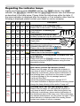
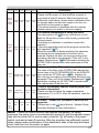
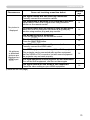
Regarding the indicator lamps . . . . 72
Phenomena that may be easily
mistaken for machine defects . . . . . . 74
Warranty and after-service. . . 77
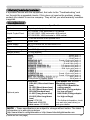
Specifications . . . . . . . . . . . . . 77
Introduction
Introduction
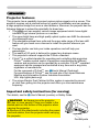
Projector features
This projector has a capability to project various picture signals onto a screen. This
projector requires only a minimal amount of space for installation and can produce
a large projected image from even a short distance. Moreover, the projector has the
following features to extend its potentiality for broad use.
9 The HDMI port can support various image equipment which have digital
interface to get clearer pictures on a screen.
9 The super bright lamp and high quality optical system can fulfill the demands
of professional uses.
9 The selectable optional lens units and the super wide range of the lens shift
feature will give much more chances to install the product wherever you
want.
9 The lens shutter can hide your inside operations and will help your
presentation.
9 The wealth of I/O ports is believed to support any business scene.
9 This projector's network supports the PJLinkTM standard.
9 PJLinkTM is a unified standard for operating and controlling data projectors.
PJLinkTM enables central control of projectors manufactured by different
vendors and projectors can be operated by a controller. PJLinkTM compliant
equipment can be managed and controlled at any time and in any place,
regardless of manufacturer.
For the command of PJLinkTM, see User's Manual (Technical)
For specifications of PJLinkTM, see the web site of the Japan Business
Machine and Information System Industries Association.
URL: http://pjlink.jbmia.or.jp
9 The unique Electric Dust Catcher Air filter system is expected to prevent
air dust from getting into the projector and offers you less maintenance
frequency.
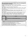
Important safety instruction (for moving)
*For details, see the User's Manual (concise) or Safety Guide.
WARNING ŹAlways move the projector
with two or more people. Place your hands in the
dented parts on the bottom of the projector when
carrying the projector.
ŹRemove all the attachments including the power
cord and cables, from the projector when carrying
the projector.
Dented parts
3
Introduction
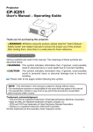
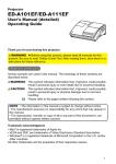
Checking the contents of package
Soon after purchasing this product, check that all the following items are included in
the package. If any items should be missing, tell your dealer immediately.
(1) Projector
(2) Lens adapter
(3) Hexagon wrench (for installation of
the optional lens unit)
(4) Power cord
(5) Computer cable
(6) Remote control
with two batteries
(7) User’s manuals (a book and a CD)
(8) Security label
(1)
(2)
(3)
LASER
INDICATOR
STANDBY/ON MY SOURCE COMPUTER
VIDEO
(4)
(5)
(6)
ID 1
ID 3
ID 2
ID 4
DIGITAL
BLANK
LASER
ENTER
FREEZE
MENU
ASPECT
SHUTTER
PbyP
AUTO
MY BUTTON
RESET
POSITION
MAGNIFY
1
3
ON
2
4
OFF
FOCUS
ZOOM
+
+
-
-
KEYSTONE
LENS SHIFT
(7)
(8)
NOTE • This product is supplied without a lens unit so that you can choose
from a range of lenses (
7
7) that can meet your requirements. Ask your dealer
about details, and prepare one or more lens unit together with this product.
• Some additional accessories or services may be required for your use. We
recommend consult with your dealer beforehand.
CAUTION ŹKeep the original packing materials, and use them correctly
when transporting or storing the product.
Attaching the lens unit
Request your dealer to install the lens unit in the projector. Be sure to leave both
removing and attaching the lens unit to the service personnel your dealer sent.
WARNING ŹUse only the lens unit specified by the manufacturer.
ŹLeave both attaching and removing the lens unit to the service personnel your
dealer sent.
ŹRead and keep the user’s manual of the lens unit.
ŹUse special caution not to drop the lens unit or knock it against something.
ŹDo not transport the projector to which the lens unit is attached.
CAUTION Keep the original packing materials for the lens unit, and use
them correctly when transporting or storing the lens unit.
NOTICE ŹDo not touch the lens surface directly.
Ź Keep the dust protector of the projector, and use it while no lens unit is
attached to the projector.
4
Part names
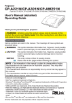
Part names
Front ring
Front cover
Projector
(1) Dust protector
17)
(2) Remote sensors (x 2) (
(3) Exhaust vents
(4) Filter cover (
69)
The filter unit and intake vent are
inside.
(5) Control panel (
6
)
6)
(6) Rear panel (
(7) Shutdown switch (
7
3)
(8) Lamp cover (
67)
The lamp unit is inside.
(9) AC IN (AC inlet) (
1
5)
(10) Power switch (
1
9,20)
10)
(11) Security bar (
(12) Security slot (
1
0)
(13) Dented part (x 2) (
3
)
(14) Elevator feet (x 2) (
2
0)
(3)
HOT!
(1)
See the NOTICE
(2)
(7)
(8)
HOT!
(9)
(4)
(10)
(11)
(12)
(14)
(6)
(5)
(13)
WARNING ŹHOT! : Do not touch around the lamp cover or the exhaust
vents during use or just after use, since it is hot.
ŹDo not look into the lens or vents while the lamp is on, since the strong light is
not good for your eyes.
ŹDo not grab the front cover or front ring to hold the projector, since you can
drop the projector.
ŹDo not handle the elevator feet without holding the projector, since the
projector may drop down.
CAUTION ŹMaintain normal ventilation to prevent the projector from
heating up. Do not cover, block or plug up the vents. Do not place anything that
can stick or be sucked to the vents, around the intake vents. Clean the air filter
periodically.
NOTICE ŹDo not touch the lens surface directly.
Ź Keep the dust protector of the projector, and use it when no lens unit is
attached to the projector.
5
Part names
Control panel
(1) STANDBY/ON button (
1
9,20)
2
8)
(2) Cursor buttons ( Ÿ/ź/Ż/Ź ) (
(3) MENU button (
2
8)
(4) COMPUTER button (
22)
(5) VIDEO button (
2
2)
The indicator
(6) DIGITAL button (
2
2)
(7) LENS SHIFT button (
2
1)
will light in
(8) ZOOM button (
2
1)
green while
(9) FOCUS button (
2
1)
the menu of
(10) SHUTTER button (
2
6)
(1)
STANDBY/ON
(2)
(3)
The
indicator of
(4) group the
selected
(5)
input port
(6) belongs to
will light in
green.
MENU
(7)
LENS SHIFT
(8)
ZOOM
COMPUTER
the function is
(9)
displayed.
VIDEO
FOCUS
DIGITAL
(10)
SHUTTER
The indicator will blink in yellow
while the lens shutter is closed.
Indicator lamp
(
7
2)
(1) POWER indicator
(2) TEMP indicator
(3) LAMP indicator
(4) SECURITY indicator
(5) SHUTTER indicator
(1) (2) (3) (4) (5)
POWER
TEMP
LAMP SECURITY SHUTTER
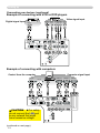
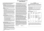
Rear panel(
10)
(1) HDMI port
(2) DVI-D port
(3) LAN port
(4) MONITOR OUT port
(5) CONTROL IN port
(6) CONTROL OUT port
(7) REMOTE CONTROL IN port
(8) REMOTE CONTROL OUT port
(9) S-VIDEO port
(10) VIDEO 1 port
(11) VIDEO 2 port
(12) COMPUTER IN1 port
(13) COMPUTER IN2 port
(14) BNC (G/Y, B/Cb/Pb
/Pb,, R/Cr/Pr
/Pr,, H, V) ports
(15) Component (Y, Cb/Pb
/Pb,, Cr/Pr
/Pr)) ports
(1) (2)(3)(4)
(9)(10)(11)
LAN
HDMI
DVI-D
CONTROL IN CONTROL OUT REMOTE
CONTROL
IN
S-VIDEO
MONITOR
OUT
COMPUTER IN1 COMPUTER IN2
OUT
VIDEO 1
R/Cr/Pr
BNC
G/Y B/Cb/Pb
H
V VIDEO 2
Y
Cb/Pb
Cr/Pr
I
O
AC IN
(5) (6) (7) (8) (15) (14) (12) (13)
CAUTION ŹUse the shutdown switch only when the projector is not turned
off following the normal procedure, since pushing this switch stops operation of
the projector without cooling it down.
6
Part names
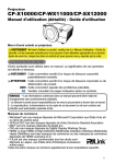
Remote control
(1) Laser pointer (
18)
It is a beam outlet.
(2) LASER INDICATOR (
1
8)
(3) LASER button (
1
8)
(4) STANDBY/ON button (
1
9,20)
(5) ID (1-4
1-4) button (
18)
(6) COMPUTER button (
22)
(7) VIDEO button (
2
2)
(8) DIGITAL button (
2
2)
(9) MY SOURCE button (
2
2)
(10) LENS SHIFT button (
2
1)
(11) ZOOM +/- button (
2
1)
(12) FOCUS +/- button (
2
1)
(13) AUTO button (
2
3)
(14) POSITION button (
2
4)
(15) ASPECT button (
2
3)
(16) KEYSTONE button (
2
4)
(17) MAGNIFY ON/OFF button (
2
5)
(18) FREEZE button (
2
5)
(19) BLANK button (
2
6)
(20) SHUTTER button (
2
6)
(21) MY BUTTON (1-4
1-4) button (
4
9)
(22) P by P button (
27)
(23) MENU button (
28)
(24) ENTER button : press the center point.
Cursor button: press the point Ÿ/ź/Ż/Ź (
2
8).
(25) RESET button (
2
8)
(26) Wired remote control port (
1
8)
(27) Battery cover (
16)
(28) Battery holder (
1
6)
(27)
(29) Frequency switch (
1
7)
(2)
(1)
(9)
LASER
INDICATOR
(4)
(5)
STANDBY/ON MY SOURCE COMPUTER
ID 1
ID 3
ID 2
ID 4
BLANK
(6)
VIDEO
(7)
DIGITAL
(8)
LASER
(3)
(19)
ENTER
(24)
(18)
FREEZE
(15)
(20)
(22)
MENU
ASPECT
SHUTTER
RESET
PbyP
AUTO
POSITION
MY BUTTON
(23)
(25)
(13)
(14)
MAGNIFY
1
3
ON
2
4
OFF
FOCUS
ZOOM
KEYSTONE
+
+
-
-
(17)
(21)
(16)
LENS SHIFT
(12)
(10)
(11)
(26)
Back of
the remote control
(28)
(29)
WARNING ŹDo not look into the beam outlet or
point the beam at people or pets while pressing the
LASER button, since the beam is not good for eyes.
CAUTION ŹNote that the laser beam may result
in hazardous radiation exposure. Use the laser pointer
only for pointing on the screen.
7
Setting up
Setting up
Read this chapter through first. Then install the projector into place.
Installation environment
This product requires an installing place that is stable, cool and airy. Check your
installation environment in accordance with the following.
WARNING ŹDo not place the product on an unstable surface such as an
uneven, tilted, or vibrating place.
ŹDo not place the product near water - for example, near a bathtub, washbowl,
kitchen sink, or laundry tub; in a wet basement, near a swimming pool, beach; or
outdoors.
CAUTION ŹDo not place the product in a dusty, smoky, or humid place for example, on a passage, in a smoking space, in a kitchen, or outdoors.
ŹDo not place the product near heat sources - for example, radiators, heat
registers, stoves, or other product (including amplifiers) that produces heat.
ŹDo not place this product in a magnetic field.
NOTICE ŹDo not place the product in a place where radio interference may
be caused.
Ź Do not place the projector in a place where any strong lights hit the remote
sensors.
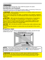
Projection style
This projector can be used by the following projection styles. Choose the style
suitable to your use.
(2) Ceiling mount
(suspended from a ceiling)
(1) Standard style
(placed on a table)
NOTE • In the case of ceiling mount, upward projection, or downward
projection, the specified mounting accessories (
77) and service are required
to install the projector. Request them from your dealer. Ask your dealer for
installation other than styles above.
WARNING ŹConsult with your dealer about installation beforehand.
ŹUse only the mounting accessories the manufacturer specified, and leave
installing and removing the projector with the mounting accessories to the
service personnel.
8
Setting up
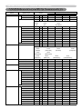
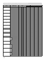
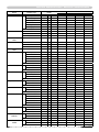
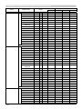
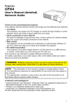
Projection distance
Refer to the following to arrange the projector and your screen. The values shown in the
following table were calculated for the model CP-X10000 with the standard lens unit SD804. See the user’s manual of your lens unit for your case. The values differ for every
combination of the projector and the lens unit.
* The values shown in the table are calculated for a full size screen: 1024×768
(a) Screen size (diagonal)
(b) Projection distance (±10%)
(c) Screen height (±10%), when the vertical lens shift is set full upward.
(b)
Projector top
(a)
(c) up
(c) down
Projector bottom
(Installation side)
(a) Screen
size
[inch (m)]
40
(1.0)
60
70
80
90
100
120
150
200
250
300
350
400
500
600
700
(1.5)
(1.8)
(2.0)
(2.3)
(2.5)
(3.0)
(3.8)
(5.1)
(6.4)
(7.6)
(8.9)
(10.2)
(12.7)
(15.2)
(17.8)
4 : 3 screen
(b) Projection distance
(c) Screen height
[m (inch)]
[cm (inch)]
min.
max.
down
up
1.7 (66) 2.3 (89) -23 (-9)
84 (33)
2.6 (103) 3.5 (136) -34 (-13) 125 (49)
3.1 (121) 4.0 (159) -40 (-16) 146 (58)
3.5 (139) 4.6 (183) -45 (-18) 167 (66)
4.0 (157) 5.2 (206) -51 (-20) 188 (74)
4.4 (175 5.8 (230) -56 (-22) 209 (82)
5.4 (211 7.0 (277) -68 (-27) 251 (99)
6.7 (266 8.8 (347) -85 (-33) 313 (123)
9.0 (356 11.8 (464) -113 (-44) 418 (164)
11.3 (447 14.8 (582) -141 (-56) 522 (206)
13.6 (537 17.8 (699) -169 (-67) 627 (247)
15.9 (628 20.7 (816) -198 (-78) 731 (288)
18.2 (718 23.7 (934) -226 (-89) 835 (329)
22.8 (899 29.7 (1168) -282 (-111) 1044 (411)
27.4 (1081 35.6 (1403) -339 (-133) 1253 (493)
32.0 (1262 41.6 (1638) -395 (-156) 1462 (576)
16 : 9 screen
(b) Projection distance
(c) Screen height
[m (inch)]
[cm (inch)]
min.
max.
down
up
1.3
(53)
1.8
(72)
2.1
2.5
2.9
3.2
3.6
4.4
5.5
7.4
9.2
11.1
13.0
14.9
18.6
22.4
26.2
(83)
(98)
(112)
(127)
(142)
(172)
(216)
(290)
(364)
(438)
(512)
(586)
(734)
(882)
(1030)
2.8
3.3
3.8
4.3
4.7
5.7
7.2
9.6
12.0
14.5
16.9
19.4
24.2
29.1
34.0
(110)
(129)
(148)
(168)
(187)
(225)
(283)
(379)
(474)
(570)
(666)
(762)
(954)
(1145)
(1337)
-33
-49
-58
-66
-74
-82
-99
-123
-164
-206
-247
-288
-329
-411
-493
-576
(-13)
(-19)
(-23)
(-26)
(-29)
(-32)
(-39)
(-49)
(-65)
(-81)
(-97)
(-113)
(-130)
(-162)
(-194)
(-227)
83
124
145
165
186
207
248
310
414
517
620
724
827
1034
1241
1447
(33)
(49)
(57)
(65)
(73)
(81)
(98)
(122)
(163)
(204)
(244)
(285)
(326)
(407)
(488)
(570)
NOTICE ŹDo not use a polarized screen, since it can cause a red image.
9
Setting up
Placement
In placing the projector in place in accordance with the preceding section
"Projection distance" (
9
) heed the following too.
WARNING ŹKeep the projector away from anything that is easy to catch
fire.
ŹDo not block or cover the openings on the projector, and keep sufficiently
space for ventilation around the projector.
• Do not use the projector on a cushiony surface such a rug, a carpet or bedding.
• Keep the projector away from any light materials such as a piece of paper that
can stick to the intake holes.
ŹDo not use the projector on an unstable stand such as a cart.
ŹPlace the projector so that nothing enters to the inside of the projector.
• Keep the projector away from any small things such as paperclips that can fall
into the inside.
• Keep the projector away from any liquids that can spill or leak into the product.
CAUTION ŹKeep the projector away from anything that is heat conductive
such as metal.
• Do not use the projector on a metallic table.
ŹKeep the projector away from anything that is weak in heat such as some kinds
of plastics.
NOTICE ŹPlace the projector so that there is nothing that blocks the
projection light to the screen.
Ź Avoid exposing directly the remote sensor to any strong lights.
Supplementary anti-theft means
This projector has the security bar for a commercial
anti-theft chain or wire up to 10 mm in diameter, and
also the security slot for the Kensington lock.
For details, see the manual of your security tool.
Security bar
Anti-theft chain or wire
NOTE • These are not provided as comprehensive theft
preventions but supplemental measures.
WARNING ŹDo not use the security slot to
prevent the projector from falling down, since it is not
designed for it.
CAUTION ŹDo not place the anti-theft chain
or wire near the projector’s exhaust vents, since the
chain or wire heated by the hot exhaust gas may
cause burns.
10
Security slot
Setting up
Connecting with your devices
Before connecting the projector to your devices, check the manual of the device in
order to make sure that the device is suitable to connect with this projector and to
check what is required for the connection.
Consult your dealer when the required accessory did not come with the product or
the accessory is damaged. It may be regulated under some standard.
After making sure that the projector and the devices are turned off, perform
the connection, according to the following instructions. Refer to the figures in
subsequent pages.
NOTE • For this product, the optional cable cover is ready to be purchased. To
place an order for it, please tell your dealer the type name of it (
77).
WARNING ŹUse only the accessories specified or recommended by
manufacturer. Modify neither a projector nor accessories.
ŹDo not connect or disconnect the projector with devices while they are
connected to a power supply except for the cases directed by the manuals of
devices.
CAUTION ŹSome connecting cable may have to have a specific length,
or a ferrite core at the end to connect to the projector, under the regulation of
electro-magnetic interference. When a ferrite core is attached to the specified
cable only at one end, connect to the projector the end that the ferrite core is
attached at.
ŹBe careful not to set a connector into a wrong port or with a wrong way.
ŹBe careful not to damage the cables. Route the cables not to be stepped on
and pinched out.
NOTICE ŹDo not turn your device on prior to the projector, except for the
cases directed by the manuals of devices.
(continued on next page)
11
Setting up
Connecting your devices (continued)
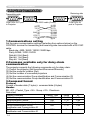
Example of connecting with VCR or DVD players
Video signal input
Digital signal input
S-VIDEO VIDEO
COMPONENT VIDEO
OUT
OUT
Y Cb/Pb Cr/Pr
OUT
HDMI
LAN
HDMI
CONTROL IN
DVI-D
REMOTE
CONTROL OUT CONTROL
MONITOR
OUT
S-VIDEO
IN
COMPUTER IN1 COMPUTER IN2
OUT
VIDEO 1
R/Cr/Pr
BNC
G/Y
B/Cb/Pb
H
V
VIDEO 2
Y
Cb/Pb
Cr/Pr
K
Example of connecting with computers
Control from the computer
Computer signal input
RS-232C
RGB OUT
RGB OUT
DVI-D
LAN
LAN
HDMI
CONTROL IN
DVI-D
REMOTE
CONTROL OUT CONTROL
S-VIDEO
MONITOR
OUT
IN
COMPUTER IN1 COMPUTER IN2
OUT
VIDEO 1
CAUTION ŹFor safety,
do not connect the LAN port
to any network that might
have excessive voltage.
R/Cr/Pr
Cb/Pb
Cr/Pr
K
(continued on next page)
12
G/Y
Y
BNC
B/Cb/Pb
H
V
VIDEO 2
RGB OUT
Setting up
Connecting your devices (continued)
Example of connecting with another projector or a display device
Computer signal input
Control from the computer
RS-232C
RGB OUT
R
LASE ATOR
INDIC
ER
PUT
COM
MY
RCE
SOU
Y/ON
NDB
STA
O
VIDE
ID
ID
TAL
DIGI
3
1
ID
ID
4
R
LASE
2
K
BLAN
ER
ENT
U
MEN
T
RESE
N
ITIO
POS
TER
EZE
FRE
SHUT
O
AUT
ECT
ASP
PbyP
MY
NIFY
MAG
ON
TON 3
BUT
1
OFF
4
NE
STO
KEY
2
T
S SHIF
LEN
M
ZOO
+
US
FOC
+
Wired
remote
control
-
LAN
HDMI
CONTROL IN
DVI-D
REMOTE
CONTROL OUT CONTROL
S-VIDEO
MONITOR
OUT
IN
COMPUTER IN1 COMPUTER IN2
OUT
VIDEO 1
R/Cr/Pr
G/Y
BNC
B/Cb/Pb
H
V
VIDEO 2
Y
Cb/Pb
Cr/Pr
K
Redirection
of an RGB input
to another display
Control of
another device by
RS-232C commands
RGB IN
RS-232C
REMOTE
CONTROL IN
Simultaneous remote control
of another projector
13
Setting up
Connecting your devices (continued)
NOTE • Be sure to read the manuals for devices before connecting them to the projector,
and make sure that all the devices are suitable to be connected with this product.
• Before connecting to a PC, check the signal level, the signal timing, and the resolution.
- Be sure to consult to the administrator of the network. Do not connect LAN port to any
network that might have excessive voltage.
- Some signal may need an adapter to input this projector.
- Some PCs have multiple screen display modes that may include some signals which
are not supported by this projector.
- Although the projector can display signals with resolution up to UXGA (1600X1200), the signal will be
converted to the projector’s panel resolution before being displayed. The best display performance
will be achieved if the resolutions of the input signal and the projector panel are identical.
• While connecting, make sure that the shape of the cable's connector fits the port to
connect with. And be sure to tighten the screws on connectors with screws.
• When connecting a laptop PC to the projector, be sure to activate the PC’s external
RGB output. (Set the laptop PC to CRT display or to simultaneous LCD and CRT
display.) For details on how this is done, please refer to the instruction manual of the
corresponding laptop PC.
• When the picture resolution is changed on a computer depending on an input,
automatic adjustment function may take some time and may not be completed. In this
case, you may not be able to see a check box to select “Yes/No” for the new resolution
on Windows. Then the resolution will go back to the original. It might be recommended
to use other CRT or LCD monitors to change the resolution.
• In some cases, this projector may not display a proper picture or display any picture on
screen. For example, automatic adjustment may not function correctly with some input
signals. An input signal of composite sync or sync on G may confuse this projector, so
the projector may not display a proper picture.
• The HDMI and DVI-D ports of this model are compatible with HDCP (High-bandwidth Digital Content
Protection) and therefore capable of displaying a video signal from HDCP compatible DVD players or the like.
About Plug-and-Play capability
Plug-and-Play is a system composed of a computer, its operating system and peripheral
equipment (i.e. display devices). This projector is VESA DDC 2B compatible. Plug-andPlay can be used by connecting this projector to a computer that is VESA DDC (display
data channel) compatible.
• Take advantage of this feature by connecting an RGB cable to the COMPUTER IN1 port
(DDC 2B compatible). Plug-and-Play may not work properly if any other type of connection is
attempted.
• Please use the standard drivers in your computer as this projector is a Plug-and-Play monitor.
NOTE for HDMI
• The HDMI supports the following signals.
-Video signal : 480i@60,480p@60,576i@50, 576p@50,720p@50/60,1080i@50/60,10
80p@50/60
-PC signals : See User’s Manual (detailed) Technical
• This projector can be connected with another equipment that has HDMI or DVI
connector, but with some equipment the projector may not work properly, something like
no video.
• Be sure to use an HDMI cable that has the HDMI logo.
• When the projector is connected with a device having DVI connector, use a DVI to HDMI cable
to connect with the HDMI input.
14
Setting up
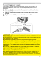
Connecting power supply
In accordance with the warnings shown below, connect the AC inlet of the
projector to the proper power outlet. The following walks you through the
connection.
Make sure that the power switch of the projector is set to the off-position
O”).
(marked with “O
Insert the socket end of the power cord into the AC IN (AC inlet) of the
projector.
Plug the other end of the power cord into the power outlet.
1.
2.
3.
Socket of the power cord
AC IN
Power switch
WARNING ŹDo not connect the projector to a power supply when the lens
unit is not attached.
ŹUse this projector from only the specified power supply in accordance with the
label indication on the projector.
ŹUse a power outlet that is close to the projector and easily accessible.
ŹDo not overload the outlet, since overloading can result in a fire or an electric
shock.
ŹUse only the power cord that came with this product and is suitable for your
power supply. If the suitable power cord did not come with this product, consult
your dealer.
ŹDo not use a damaged power cord. If the power cord you need is damaged,
ask your dealer for a new power cord of the same type.
ŹDo not handle the power cord with wet hands.
ŹDo not repair or modify the power cord.
ŹBe careful not to damage the power cord. Route the power cord so that it is
not likely to be walked on or pinched by items placed upon or against them.
ŹConnect firmly the power cord not to result in loose connection. Do not use a
loose or unsound power outlet.
15
Remote control
Remote control
Putting batteries
The remote control needs the two batteries of the following type.
HITACHI MAXELL, part number LR6 or R6P
The batteries that came with the product are a type suitable to this remote control.
The following walks you through loading batteries into the remote control.
the battery cover in the back of the
1. Remove
remote control. Push lightly the knob of the
battery cover while pulling it up.
the batteries into the battery holder, according to the
2. Put
polarity markings “+” and “-“ inside the holder.
3. Put the battery cover back into place until it clicks.
NOTE • If the remote control malfunctions, try replacing the batteries with
fresh ones.
WARNING ŹBe careful not to press the LASER button when loading the
batteries. It is dangerous if a laser beam is unintentionally turned on. Please
refer to the section "Laser pointer" (
18).
ŹBe careful of handling batteries, since a battery can cause explosion, cracking
or leakage that could result in a fire, injury, or environment pollution.
• Use only the specified batteries. Do not use batteries of different types.
• When replacing, replace both of the batteries with new batteries of the same
type. Do not use a new battery with a used battery.
• Do not use a battery with damage, such as scratches, dents, rust or leakage.
• Make sure the plus and minus terminals are correctly aligned when loading a
battery.
• Do not work on a battery; for example recharging or soldering.
• If the remote control is not used for a long period of time, remove the batteries.
• Keep batteries in a dark, cool and dry place. Never expose a battery to a fire or
water.
• Keep batteries away from children and pets.
• When a battery leaked, wipe the leakage out well with a waste cloth. If the
leakage adhered to your body, immediately rinse it well with water. When a
battery leaked in the battery holder, replace the batteries after wiping the leakage
out.
• Obey the local laws on disposing a battery.
16
Remote control
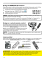
Transmitting condition
Remote
sensors
The remote control works with the remote
sensors on the projector using infrared light
(Class 1 LED). The remote sensor senses the
remote control signals reached into the range
within 60 degrees (to right and left) and 3 meters
about from the sensor.
Remote
sensor
30º
30º
STANDB
Y/ON
MY
SOURCE
Approx.
3m
COMPUT
ID 1
ER
ID 3
ID 2
BLANK
LASER
INDICATOR
ID 4
VIDEO
DIGITAL
LASER
ENTER
FREEZE
ASPECT
SHUTTER
PbyP
MENU
RESET
AUTO
MY
1
BUTTON
3
2
N
OFF
ZOOM
+
-
POSITIO
MAGNIFY
ON
4
FOCUS
+
-
KEYSTO
NE
LENS
SHIFT
NOTE • You can inactivate one or two sensors from the three sensors using
the item REMOTE RECEIVE. of the SERVICE menu under the OPTION menu.
• When you want to use two or more projectors of this type at the same time
and the same place, utilize the REMOTE ID function. The buttons of ID 1
1, ID 2
2,
ID 3 and ID 4 on the remote control can name the projector given the same ID
number as the button by the item REMOTE ID of the SERVICE menu under the
OPTION menu.
NOTICE ŹAvoid exposing directly the remote sensor to any strong lights.
ŹDo not put anything between the remote control and the remote sensor on the
projector, since it may interfere with transmission of the remote control signals.
Changing the frequency of remote control signal
The accessory remote control has the choice of
mode 1 or mode 2, in the frequency of its signal.
If the remote control does not function properly,
attempt to change the signal frequency.
Please remember that the “REMOTE FREQ.” in
SERVICE item of OPTION menu (
51) of the
projector to be controlled should be set to the
same mode as the remote control.
To set the mode of the remote control, slide the
knob of the frequency switch inside the battery
cover into the position indicated by the mode
number to choose.
Inside of
the battery cover
Frequency switch
2
1
Back of the
remote control
17
Remote control
Using the REMOTE ID function
This is the function to define which projector is controlled by the remote control. Utilize
this function when you use some projectors of the same type at the same time.
Set the ID number to the projector beforehand,
VIDEO
referring to the item “REMOTE ID” item (
5
2).
ID 1
ID 3
DIGITAL
Press a ID button on the remote control. The ID button
ID 4
ID 2
selected will light for 3 seconds.
1.
2.
NOTE • Each time you press any button (except ID buttons), the ID button of
current selected ID number will light.
• To confirm the projector's current ID, press any ID button for 3 seconds. Its
number will be shown on each screen regardless of set ID of projector.
Using as a wired remote control
STA
ID
ID
BLA
The accessory remote control works as a wired remote control,
when the wired control port at the bottom of the remote control
connects with the REMOTE CONTROL port on the back of the
projector via an audio cable with 3.5 diameter stereo mini plugs.
This function is useful when a wireless remote signal
may not reliably reach the projector.
NDB
Y/O
N
MY
FRE
ASP
MONITOR
OUT
S-VIDEO
SHU
NIFY
-
G/Y B/Cb/Pb
U
ET
N
MAG
ON
OFF
ZOO
M
+
BNC
VIDEO 1
MEN
RES
ITIO
3
US
+
-
R/Cr/Pr
ER
POS
TON
4
COMPUTER
TTER
O
BUT
2
FOC
OUT
ER
EO
ITAL
EZE
AUT
MY
1
R
VID
DIG
ER
ECT
Pby
P
DVI-D
CONTROL IN CONTROL OUT REMOTE
CONTROL
IN
LASE
INDIC R
ATO
PUT
3
4
LAS
MI
RCE
COM
ID
ID
ENT
SOU
1
2
NK
LEN
KEY
S SHI
STO
NE
FT
H
Y
Cb/Pb
Cr/Pr
NOTE • To connect the remote control with the projector, use an audio cable
with 3.5 diameter stereo mini plugs.
Laser pointer
This remote control has a laser pointer in place of a finger or rod. The laser beam
works and the LASER INDICATOR lights while the LASER button is pressed.
Laser aperture
R
R
SE TO
LA ICA
IND
N
MY
SO
UR
CO
CE
MP
UT
ER
VID
LASER button
EO
Y/O
DB
L
AN
ST
ID
ID
ITA
3
DIG
1
ID
4
LA
ID
LASER INDICATOR
SE
R
2
BL
AN
K
EN
TE
R
ME
NU
RESE
FR
EE
ZE
AS
PE
SHUT
TER
CT
T
ION
SIT
PO
AU
TO
IFY
GN
MA
yP
Pb
ON
TT
MY
BU
3
ON
F
OF
1
4
2
KE
FO
CU
OM
ZO
+
S
+
YS
TO
LE
NE
NS
SH
IFT
-
WARNING ŹUse the laser beam of the remote control only for the pointer
on the screen. Do not apply the laser beam to anything except the screen.
• Never hit eyes by the laser beam since the laser beam can injure eyes.
• Do not apply the laser beam to anything except the screen.
18
Operating
Operating
Turning on
The following walks you through the steps to turn the projector on. For other
devices, follow the manual of each.
Make sure that the power cord is firmly and
correctly connected to the projector and the outlet.
Power
POWER indicator
Press down the side marked “II” on the power
switch
switch.
The POWER indicator will light up in steady
orange.
Then wait for the buttons to become ready. It may
take several seconds.
Press the STANDBY/ON button (on the projector
or the remote control).
The projection lamp will light up and the POWER
indicator will begin blinking in green. When the
power is completely on, the indicator will stop
STANDBY/ON
button
blinking and light in steady green.
To display the picture, select an input signal according to the section "Displaying
22).
and switching the image" (
1.
2.
SHUTTER SECURITY LAMP TEMP POWER
STANDBY/ON
3.
STANDBY/ON
NOTE • When the item DIRECT ON of the OPTION menu is set to the ON,
and that the projector was turned off by only the power switch without using
the STANDBY/ON button, switching the power switch on turns the projector on
without the formal procedure shown above.
WARNING ŹDo not look directly into the lens or the openings on the
projector while the lamp is on.
ŹDo not approach the lamp cover and the exhaust vents, while the projection
lamp is on.
NOTICE ŹDo not turn your device on prior to the projector, except for the
cases directed by the manuals of devices.
19
Operating
Turning off
The following walks you through the steps to turn the projector off.
the STANDBY/ON button on the projector
1. orPress
the remote control.
The message "Power off?" will appear on the
screen for about 5 seconds.
Power
switch
POWER indicator
SHUTTER SECURITY LAMP TEMP POWER
STANDBY/ON
Press the STANDBY/ON button again while the
message is shown.
The projector lamp will go off, and the POWER
indicator will begin blinking in orange.
Then the POWER indicator will stop blinking
and light in steady orange when lamp cooling is
complete.
STANDBY/ON button
After making sure that the POWER indicator lights in steady orange, and
press down the side marled “O
O” on the power switch.
The POWER indicator will go off.
For other devices, follow the manual of each.
2.
STANDBY/ON
3.
NOTE • Use the shutdown switch only when the projector can be not turned
off by normal procedure.
WARNING ŹDo not approach the lamp cover and the exhaust vents for a
while after the lamp goes out, since they may be hot and could cause burns.
NOTICE ŹTurn your device off prior to the projector, except for the cases
directed by the manuals of devices.
Using the elevator feet
Lengthening or shortening the length of the elevator feet shifts the projection
position and the projection angle.
Turn the elevator feet each to adjust their length
5°
max.
30 mm
WARNING ŹDo not lengthen the elevator feet to 30 mm or more. The foot
lengthened exceeding the limit may come off and drop the projector down, and
result in an injury or damaging the projector.
CAUTION ŹDo not place the projector with an inclination of 5 degrees
or more. The projector leaned exceeding the limit could cause malfunction and
shorten the life of the projector.
20
Operating
Using the functions for the lens
ZOOM / FOCUS
Press the ZOOM / FOCUS button. The ZOOM / FOCUS
dialog will appear. Adjust the zoom / focus using the Ż/Ź
button while the dialog is displayed. Press the ź button to
select "EXIT" on the dialog. It finishes the OSD menu.
LENS SHIFT
Press the LENS SHIFT button. The LENS SHIFT
dialog will appear. Using the Ÿ/ź/Ż/Ź buttons
while the dialog is displayed shifts the lens.
CENTERING
In the LENS SHIFT dialog:
Press the DIGITAL button.
In the standby mode:
Press the LENS SHIFT and the DIGITAL
buttons for 3 seconds at the same time.
Ɣ While the lens is shifting, the menu will disappears and the icon of hourglass will
appears on screen. Shifting may takes some time. Depending on the case, it
may reach one minute.
Ɣ The LENS SHIFT indicator lights up or blinks in green while the lens is shifting.
Then the indicator will stop blinking and light for 3 seconds in steady green
when the centering is complete.
Ɣ When the lens is located in the center already, pressing the DIGITAL button in
the LENS SHIFT dialog lights in steady green the LENS SHIFT indicator for 3
seconds.
LENS MEMORY SAVE / LOAD / CLEAR
This projector is equipped with memory functions for the lens adjustments (zoom,
focus and shift).
To display the LENS MEMORY dialog, select the LENS MEMORY on the ZOOM,
FOCUS or LENS SHIFT dialog. Then the LENS MEMORY dialog will appear.
SAVE:To save the current lens adjustments,
select a SAVE-(1-3) and press Ź or ENTER
button.
LOAD:To load a saved adjustments, select the
LOAD-(1-3) and press Ź or ENTER button.
When the MY BUTTON button is allocated to
the LOAD-(1-3) the memory can be loaded
without the LENS MEMORY dialog.
CLEAR:Selecting the CLEAR LENS MEMORY in the LENS MEMORY dialog
displays CLEAR LENS MEMORY dialog. Select the number to be cleared
using Ÿ/ź buttons and press the Ź button. The dialog to check your intention
will come out. Then press the Ź button again in the dialog.
21
Operating
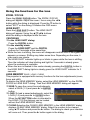
Displaying and switching the image
Press the COMPUTER button to select an input port for the
1. RGB
signal.
Each time you press the button, the projector switches its
RGB input port from the current port as below.
LASER
INDICATOR
STANDBY/ON MY SOURCE COMPUTER
COMPUTER IN1 ÆCOMPUTER IN2 ÆBNC Ɣ While ON is selected for AUTO SEARCH item in OPTION menu, the
projector will keep checking every port sequentially till an input signal is
detected (
47). If COMPUTER button is pushed when VIDEO 1
1, VIDEO
2, S-VIDEO
S-VIDEO, Component, HDMI or DVI-D port is selected, the projector will
check COMPUTER IN1 port first.
Press the VIDEO button to select an input for video signal.
1. Each
time you press the button, the projector switches its
STANDBY/ON MY SOURCE COMPUTER
VIDEO
ID 1
ID 3
video input port as below.
COMPONENT (Y, Cb/Pb, Cr/Pr) Æ
S-VIDEO Æ
VIDEO 1 Æ
VIDEO 2
Ɣ While ON is selected for AUTO SEARCH item in OPTION menu, the projector
will keep checking every port sequentially till an input signal is detected (
47).
If VIDEO button is pushed when COMPUTER IN1 or COMPUTER IN2 port is
selected, the projector will check Component port first.
VIDEO
1.
Press the DIGITAL button to select an input for digital signal.
Each time you press the button, the projector switches its
digital input port as below.
DVI-D
HDMI
ID 1
ID 3
ID 2
ID 4
DIGITAL
Ɣ While ON is selected for AUTO SEARCH item in OPTION menu, the projector
will keep checking every port sequentially till an input signal is detected (
47).
If DIGITAL button is pushed when Component, S-VIDEO
S-VIDEO, VIDEO 1 or VIDEO 2
port is selected, the projector will check HDMI port first.
Press the MY SOURCE button on the remote control. The
1. input
signal will be changed into the signal you set as MY
SOURCE(
4
9).
LASER
INDICATOR
STANDBY/ON MY SOURCE COMPUTER
VIDEO
Ɣ This function also can use for document camera. Select the input port that
connected the document camera.
22
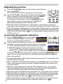
Operating
Selecting an aspect ratio
Press the ASPECT button on the remote control.
1. Each
time you press the button, the projector switches the mode for aspect
ratio in turn.
For a computer signal
NORMAL Æ
4:3 Æ
16:9 Æ
16:10*
Æ SMALL* Æ
NATIVE* Æ
FULL*
For an HDMI or DVI-D signal
NORMAL Æ
4:3 Æ
16:9 Æ
16:10* Æ
14:9 Æ
SMALL* Æ
NATIVE* Æ
FULL*
For a video signal, s-video signal or component video signal
4:3 Æ
16:9 Æ
16:10* Æ
14:9 Æ
SMALL* Æ
NATIVE* Æ
FULL*
For no signal
4:3 (fixed, except CP-WX11000) / FULL (fixed,
CP-WX11000)
Ɣ *16:10 / FULL: CP-WX11000 only. NATIVE: Except
CP-X10000. SMALL: Except CP-WX11000.
Ɣ The NORMAL mode keeps the original aspect ratio of
the signal.
ENTER
FREEZE
ASPECT
MENU
SHUTTER
RESET
Using the automatic adjustment feature
Press the AUTO button on the remote control.
1. Pressing
this button performs the following.
LASER
INDICATOR
STANDBY/ON MY SOURCE COMPUTER
For a computer signal
VIDEO
The vertical position, the horizontal position and the
ID 3
ID 1
horizontal phase will be automatically adjusted.
DIGITAL
ID 4
ID 2
Make sure that the application window is set to its
maximum size prior to attempting to use this feature.
BLANK
LASER
A dark picture may still be incorrectly adjusted. Use a
bright picture when adjusting.
For a video signal and s-video signal
The video format best suited for the respective input signal will be selected
automatically. This function is available only when the AUTO is selected for
the VIDEO FORMAT item in the INPUT menu (
3
7). The vertical position
and horizontal position will be automatically set to the default.
For a component video signal
The vertical position, horizontal position and horizontal phase will be
automatically set to the default.
Ɣ The automatic adjustment operation requires approx. 10 seconds. Also
please note that it may not function correctly with some input. When this
function is performed for a video signal, a certain extra such as a line may
appear outside a picture.
Ɣ The items adjusted by this function may vary when the FINE or DISABLE is
selected for the AUTO ADJUST item of the SERVICE item in the OPTION
menu (
50).
23
Operating
Adjusting the position
Press the POSITION button on the remote control when no
1. menu
is indicated.
ENTER
The “POSITION” indication will appear on the screen.
Use the Ÿ/ź/Ż/Ź cursor buttons to adjust the picture position.
FREEZE
MENU
When you want to reset the operation, press the RESET
button on the remote control during the operation.
SHUTTER
RESET
ASPECT
To complete this operation, press the POSITION button
AUTO
PbyP
POSITION
again. Even if you do not do anything, the dialog will
automatically disappear after a few seconds.
Ɣ When this function is performed on a video signal, s-video signal or component
video signal, some image such as an extra-line may appear at outside of the picture.
Ɣ When this function is performing on a Video signal, S-Video signal, or component
signal of 480i@60 or 576i@50 input the range of this adjustment depends on the
OVER SCAN in IMAGE menu (
3
4). It is not possible to adjust when the OVER
SCAN is set to 10.
2.
Correcting the keystone distortion
the KEYSTONE button on the remote
1. Press
control. A dialog will appear on the screen
2.
2
4
OFF
to aid you in correcting the distortion.
KEYSTONE
Use the Ÿ/ź cursor buttons to select AUTO or MANUAL
operation, and press the Ź button to perform the following.
1) AUTO executes automatic vertical keystone correction.
2) MANUAL displays a dialog for keystone correction.
Use the Ÿ/ź cursor buttons to select the direction to
correct ( or ) then use the Ż/Ź buttons for adjustment.
To close the dialog and complete this operation, press the KEYSTONE button
again. Even if you don’t do anything, the dialog will automatically disappear
after a few seconds.
FOCUS
ZOOM
+
+
Ɣ The adjustable range of this function will vary among inputs. For some input, this
function may not work well.
Ɣ When V:INVERT or H&V:INVERT is selected to the MIRROR item in the SETUP
menu, if the projector screen is inclined or angled downward, this function may
not work correctly.
Ɣ When the zoom adjustment is set to the TELE (telephoto focus), this function
may be excessive. This function should be used when the zoom adjustment is
set to the full WIDE (wide-angle focus) whenever possible.
Ɣ When the projector is placed on the level (about ±3°), this function may not work.
Ɣ When the projector is inclined to near ±30 degree or over, this function may not work well.
Ɣ When the vertical lens shift is not set fully upward (not set fully downward for the
optional lens type USL-801 only (
5
1)), this function may not work well.
Ɣ When the horizontal lens shift is not set to the center, this function may not work well.
Ɣ This function will be unavailable when Transition Detector is on (
6
4).
24
Operating
Using the magnify feature
the ON button of MAGNIFY on the remote control.
1. Press
The “MAGNIFY” indication will appear on the screen and
the projector will go into the MAGNIFY mode. In the Magnify
mode, the picture will be zoomed. The indication will
disappear in several seconds with no operation.
AUTO
PbyP
MY BUTTON
POSITION
MAGNIFY
1
3
ON
2
4
OFF
Use the Ÿ/ź cursor buttons to adjust the zoom level. To move the zoom
2. area,
press the POSITION button in the MAGNIFY mode, then use the
Ÿ/ź/Ż/Ź cursor buttons to move the area. And to finalize the zoom area,
press the POSITION button again.
To exit from the MAGNIFY mode and restore the screen to normal, press the
OFF button of MAGNIFY on the remote control.
Ɣ The projector automatically exits from the MAGNIFY mode when the input
signal is changed or when the display condition is changed.
Ɣ In the MAGNIFY mode, the keystone distortion condition may vary, it will be
restored when the projector exits from the MAGNIFY mode.
NOTE • The zoom level can be finely adjusted. Closely watch the screen to
find the level you want.
Temporarily freezing the screen
Press the FREEZE button on the remote control.
1. The
“FREEZE” indication will appear on the screen (however,
the indication will not appear when the OFF is selected for
the MESSAGE item in the SCREEN menu (
4
5)), and the
projector will go into the FREEZE mode, which the picture is
frozen.
To exit the FREEZE mode and restore the screen to normal,
press the FREEZE button again.
BLANK
LASER
ENTER
FREEZE
MENU
Ɣ The projector automatically exits from the FREEZE mode when some control
buttons are pressed.
Ɣ If the projector continues projecting a still image for a long time, the LCD
panel might possibly be burned in. Do not leave the projector in the FREEZE
mode for too long.
25
Operating
Temporarily blanking the screen
Press the BLANK button on the remote control.
1. The
blank screen will be displayed instead of the screen of
input signal. Please refer to the BLANK item in SCREEN
menu (
42).
To exit from the blank screen and return to the input signal
screen, press the BLANK button again.
VIDEO
ID 1
ID 3
ID 2
ID 4
DIGITAL
BLANK
LASER
Ɣ The projector automatically exits from the BLANK mode when some control
buttons are pressed.
Temporarily shutting the image
Pressing the SHUTTER button closes or opens the mechanical lens shutter.
1. The
closed shutter blocks the projection light, so that it can black out the
screen.
Ɣ The SHUTTER indicator on the projector blinks while the shutter is closed.
Ɣ The projector will turn off automatically when the time set up by the SHUTTER
TIMER passes (
48).
Ɣ When turning the power off with the STANDBY/ON button (
2
0), the lens
shutter closed opens automatically. If the power supply is stopped while opening
or closing the lens shutter, the moving of the lens shutter is stopped too.
However, when turning the projector on, the lens shutter closed or incompletely
opened opens automatically.
ENTER
FREEZE
26
MENU
ASPECT
SHUTTER
RESET
Pb P
AUTO
POSITION
Operating
PbyP (Picture by Picture)
The PbyP is a function to display two different picture signals on a screen that is
split in two areas for each signal. Some of functions can be used with the same
operation as it for the normal mode (not in the PbyP mode). There are some
operations available only in the PbyP mode.
Starting the PbyP
Press the PbyP button on the
remote control, then the PbyP
function will be started. To quit
the PbyP mode, press the button
again.
FREEZE
MENU
ASPECT
SHUTTER
RESET
PbyP
AUTO
POSITION
normal mode
PbyP mode
setting information
Showing the setting information
The setting information is displayed for several
seconds when the PbyP function is started. It shows
the input signal information for each area. Also, there
will be a yellow frame and speaker mark with one of the area that is the main area
where most of operations are effective. The information can be displayed using
the cursor buttons Ÿ/ź/Ż/Ź when the setting information is not on the screen.
main area
main area
COMPUTER IN1
0
0
0
HDMI
0
0
0
0
0
0
0
0
0
Video 2
Video 1
0
0
BNC
S-Video
0
COMPUTER IN2
Scart RGB
Main
Component
Sub
BNC
<signal combination>
HDMI
Press the COMPUTER
COMPUTER, VIDEO or DIGITAL button
while in the PbyP mode, the menu to select the
input signal will be appeared. Choose a signal using
the cursor buttons Ÿ/ź. If you want to change the signal in
the sub area, switch the main area using the cursor buttons
Ż/Ź first. Displaying the same signal on the both areas is
not allowed. For other combinations of the input signal, refer
to the right table. Any combinations marked with X can not be
selected.
DVI-D
Changing the picture input signal
sub area
COMPUTER IN2
Most of operations are effective for the main area
only. Also the audio input signal paired with the
picture input signal for the main area is assigned
as the audio output signal. The main area can be
changed using the cursor buttons Ż/Ź when the
setting information is on the screen.
COMPUTER IN1
Changing the main area
0
0
0
0
0
0
0
0
0
0
0
0
0
0
0
X
0
X
X
X
X
0
X
DVI-D
0
0
0
Component
0
0
0
0
0
0
0
0
Scart RGB
0
0
0
X
X
X
X
X
X
S-Video
0
0
0
X
X
X
X
Video 1
0
0
0
X
X
0
X
X
Video 2
0
0
0
X
X
0
X
X
0
X
X
X
X
X
X
Using the PbyP SWAP function
Press the MY BUTTON assigned the PbyP SWAP
49). The position of the both area is exchanged
(
without any setting change.
NOTE •For some signals, it may not be displayed correctly in the PbyP mode,
even if it can be displayed properly in the normal mode.
27
Operating
Using the menu function
This projector has the following menus: PICTURE, IMAGE, INPUT, SETUP, SCREEN, OPTION,
NETWORK, SECURITY and EASY MENU. The EASY MENU consists of functions often used, and
the other menus are classified into each purpose and brought together as the ADVANCED MENU.
Each of these menus is operated using the same methods with the Ÿ/ź/Ż/Ź, ENTER and RESET
buttons. The buttons of the same name on the remote control and on the projector function equally.
LASER
INDICATOR
ENTER button
STANDBY/ON
STANDBY/ON MY SOURCE COMPUTER
VIDEO
ID 1
ID 3
ID 2
ID 4
DIGITAL
BLANK
ENTER
Cursor buttons
LASER
ENTER
MENU
FREEZE
MENU button
ASPECT
SHUTTER
PbyP
AUTO
MY BUTTON
FREEZE
MENU
RESET
POSITION
MAGNIFY
1
3
ON
2
4
OFF
FOCUS
ZOOM
+
+
-
-
MENU
RESET button
ASPECT
SHUTTER
RESET
KEYSTONE
LENS SHIFT
Start / finish the menu
To start the MENU, press the MENU button. The MENU
you last used (EASY or ADVANCED) will appear. EASY
MENU has priority to appear just after powered on. To
finish the MENU, press the MENU button again.
If you want to change it to EASY/ADVANCED MENU,
select the EASY/ADVANCED MENU on the menu.
Indication in OSD (On Screen Display)
The meanings of the general words on the OSD are as follows.
Indication
Meaning
EXIT
Selecting this word finishes the OSD menu. It's the same as pressing the
MENU button.
RETURN
CANCEL or NO
OK or YES
Selecting this word returns the menu to the previous menu.
Selecting this word cancels the operation in the present menu and
returns to the previous menu.
Selecting this word executes the prepared function or shifts the menu to
the next menu.
NOTE Ɣ If you want to move the menu position, use the Ÿ/ź/Ż/Ź buttons after pressing
the POSITION button.
Ɣ Some functions cannot be performed when a certain input port is selected, or
when a certain input signal is displayed.
Ɣ When you want to reset the operation, press the RESET button on the remote control
during the operation. Note that items whose functions are performed simultaneously with
operation (ex. LANGUAGE, H PHASE etc.) cannot be reset.
Ɣ Even if you do not do anything, the dialog will automatically disappear after about 30 seconds.
28
EASY MENU
EASY MENU
From the EASY MENU, items shown in the table
below can be performed.
Select an item using the Ÿ/ź cursor buttons on the
projector or remote control. Then perform it according
to the following table.
Item
ASPECT
AUTO
KEYSTONE
Description
Using the Ż/Ź buttons switches the mode for aspect ratio.
3
4).
See the ASPECT item in IMAGE menu (
Using the Ź button executes the auto keystone function.
See the AUTO KEYSTONE item in SETUP menu (
40).
KEYSTONE
Using the Ż/Ź buttons corrects the vertical keystone distortion.
KEYSTONE item in SETUP menu (
40).
See the
KEYSTONE
Using the Ż/Ź buttons corrects the horizontal keystone distortion.
KEYSTONE item in SETUP menu (
41).
See the
Using the Ż/Ź buttons switches the picture mode.
The picture modes are combinations of GAMMA and COLOR
TEMP settings. Choose a suitable mode according to the projected
source.
NORMAL Ù
CINEMA Ù
DYNAMIC Ù
BOARD(BLACK)
DAYTIME Ù
WHITEBOARD Ù
BOARD(GREEN)
PICTURE MODE
NORMAL
CINEMA
DYNAMIC
BOARD(BLACK)
BOARD(GREEN)
WHITEBOARD
DAYTIME
COLOR TEMP
2 MID
3 LOW
1 HIGH
4 Hi-BRIGHT-1
5 Hi-BRIGHT-2
2 MID
6 Hi-BRIGHT-3
GAMMA
1 DEFAULT
2 DEFAULT
3 DEFAULT
4 DEFAULT
4 DEFAULT
5 DEFAULT
6 DEFAULT
• When the combination of GAMMA and COLOR TEMP differs
from pre-assigned modes above, the display on the menu for the
PICTURE MODE is “CUSTOM”. Please refer to the GAMMA and
31, 32) items in PICTURE menu.
COLOR TEMP (
• When this function is performed, lines or other distiortions may appear.
(continued on next page)
29
EASY MENU
Item
ECO MODE
MIRROR
Description
Using the Ż/Ź buttons turns off/on the eco mode.
4
1).
See the ECO MODE item in SETUP menu (
Using the Ż/Ź buttons switches the mode for mirror status.
41).
See the MIRROR item in SETUP menu (
RESET
Performing this item resets all of the EASY MENU items except the
FILTER TIME and LANGUAGE.
A dialog is displayed for confirmation. Selecting the OK using the Ź
button performs resetting.
FILTER TIME
The usage time of the air filter is shown in the menu.
Performing this item resets the filter time which counts usage time
of the air filter.
A dialog is displayed for confirmation. Selecting the OK using the Ź
button performs resetting.
48).
See the FILTER TIME item in OPTION menu (
LANGUAGE
Using the Ż/Ź buttons changes the display language.
See the LANGUAGE item in SCREEN menu (
4
2).
Press the Ź or ENTER button to use the menu of PICTURE,
ADVANCED MENU IMAGE, INPUT, SETUP, SCREEN, OPTION, NETWORK or
SECURITY.
EXIT
30
Press the Ż or ENTER button to finish the OSD menu.
PICTURE menu
PICTURE menu
From the PICTURE menu, items shown in the table
below can be performed.
Select an item using the Ÿ/ź cursor buttons on the
projector or remote control, and press the Ź cursor
button on the projector or remote control, or the
ENTER button on the remote control to execute the
item. Then perform it according to the following table.
Item
BRIGHTNESS
CONTRAST
Description
Using the Ż/Ź buttons adjusts the brightness.
Dark Ù
Light
Using the Ż/Ź buttons adjusts the contrast.
Weak Ù
Strong
Using the Ÿ/ź buttons switches the gamma mode.
Ù
Ù
3 CUSTOM
Ù
Ù
1 DEFAULT Ù 1 CUSTOM Ù 2 DEFAULT Ù 2 CUSTOM Ù 3 DEFAULT
6 CUSTOM
6 DEFAULT Ù 5 CUSTOM Ù 5 DEFAULT Ù 4 CUSTOM Ù 4 DEFAULT
To adjust CUSTOM
GAMMA
Selecting a mode whose name includes CUSTOM and then
pressing the Ź button or the ENTER button displays a dialog to aid
you in adjusting the mode.
This function is useful when you want to
change the brightness of particular tones.
Choose an item using the Ż/Ź buttons, and
adjust the level using the Ÿ/ź buttons.
You can display a test pattern for checking the effect of your
adjustment by pressing the ENTER or VIDEO button.
Each time you press the ENTER or VIDEO button,
the pattern changes as below.
No pattern Ö
Gray scale of 9 steps
Ramp Õ
Gray scale of 15 steps
The eight equalizing bars correspond to eight tone levels of the test
pattern (Gray scale of 9 steps) except the darkest in the left end.
If you want to adjust the 2nd tone from left end on the test pattern,
use the equalizing adjustment bar “1”. The darkest tone at the left
end of the test pattern cannot be controlled with any of equalizing
adjustment bar.
• When this function is performed, lines or
other distortions may appear.
(continued on next page)
31
PICTURE menu
Item
Description
Using the Ÿ/ź buttons switches the color temperature mode.
Ù
Ù
3 CUSTOM
Ù
Ù
3 LOW
6 Hi-BRIGHT-3
Ù
Ù
1 HIGH Ù 1 CUSTOM Ù 2 MID Ù 2 CUSTOM
6 CUSTOM
5 CUSTOMÙ5 Hi-BRIGHT-2Ù4 CUSTOMÙ4 Hi-BRIGHT-1
To adjust CUSTOM
COLOR TEMP
Selecting a mode whose name
includes CUSTOM and then
pressing the Ź button or the
ENTER button displays a
dialog to aid you in adjusting
the OFFSET and GAIN of the
selected mode.
OFFSET adjustments change the color intensity
on the whole tones of the test pattern.
GAIN adjustments mainly affect color intensity
on the brighter tones of the test pattern.
Choose an item using the Ż/Ź buttons, and adjust the level using
the Ÿ/ź buttons.
You can display a test pattern for checking the effect of your
adjustment by pressing the ENTER or VIDEO button.
Each time you press the ENTER or VIDEO button, the pattern
changes as below.
No pattern Ö
Gray scale of 9 steps
Ramp Õ
Gray scale of 15 steps
• When this function is performed, lines or other
distortion may appear.
COLOR
Using the Ż/Ź buttons adjusts the strength of whole color.
Weak Ù
Strong
• This item can be selected only for a video signal, s-video,
component video, HDMI or DVI-D signal when the VIDEO is
3
7).
selected on the DIGITAL FORMAT item (
TINT
Using the Ż/Ź buttons adjusts the tint.
Reddish Ù
Greenish
• This item can be selected only for a video signal, s-video,
component video, HDMI or DVI-D signal when the VIDEO is
selected on the DIGITAL FORMAT item (
3
7).
SHARPNESS
Using the Ż/Ź buttons adjusts the sharpness.
Weak Ù
Strong
• There may be some noise and/or the screen may flicker for a
moment when an adjustment is made. This is not a malfunction.
(continued on next page)
32
PICTURE menu
Item
Description
Using the Ÿ/ź cursor buttons changes the active iris control mode.
PRESENTATION ÙTHEATER ÙMANUAL
PRESENTATION
ACTIVE IRIS
THEATER
MANUAL
Feature
The active iris displays the best presentation
image for both bright and dark scenes.
The active iris displays the best theater image for
both bright and dark scenes.
The active iris is set to fixed brightness (0:dark 7:bright)
• The screen may flicker when the PRESENTATION or THEATER
modes are selected. If this occurs select MANUAL.
This projector has 4 memories for adjustment data (for all the items
of the PICTURE menu).
Selecting a function using the Ÿ/ź buttons and pressing the Ź or
ENTER button performs each function.
SAVE-1 Ù
SAVE-2 Ù
SAVE-3 Ù
SAVE-4
LOAD-4 Ù
LOAD-3 Ù
LOAD-2 Ù
LOAD-1
MY MEMORY
SAVE-1, SAVE-2, SAVE-3, SAVE-4
Performing a SAVE function saves the current adjustment data into
the memory linked in the number included in the function’s name.
• Remember that the current data being stored of a memory will be
lost by saving new data into the memory.
LOAD-1, LOAD-2, LOAD-3, LOAD-4
Performing a LOAD function loads the data from the memory linked
in the number included in the function’s name, and adjusts the
picture automatically depending on the data.
• The LOAD functions whose linked memory has no data are
skipped.
• Remember that the current adjusted condition will be lost by
loading data. If you want to keep the current adjustment, please
save it before performing a LOAD function.
• There may be some noise and the screen may flicker for a
moment when loading data. This is not malfunction.
• The LOAD functions can be also performed by the MY MEMORY
button which can be set by the MY BUTTON item in OPTION menu
(
4
9).
33
IMAGE menu
IMAGE menu
From the IMAGE menu, items shown in the table
below can be performed.
Select an item using the Ÿ/ź cursor buttons on the
projector or remote control, and press the Ź cursor
button on the projector or remote control, or ENTER
button on the remote control to execute the item.
Then perform it according to the following table.
Item
Description
Using the Ÿ/ź buttons switches the mode for aspect ratio.
For a COMPUTER signal
NORMAL Ù
4:3 Ù
16:9 Ù
16:10*
NATIVE* Ù
FULL*
Ù SMALL* Ù
For an HDMI or DVI-D signal
NORMAL Ù
4:3 Ù
16:9 Ù
16:10* Ù
14:9 Ù
SMALL* Ù
NATIVE* Ù
FULL*
ASPECT
For a Video signal, S-video signal or component video signal
4:3 Ù
16:9 Ù
16:10* Ù
14:9 Ù
SMALL* Ù
NATIVE* Ù
FULL*
For no signal
4:3 (fixed, except CP-WX11000) / FULL (fixed, CP-WX11000)
• *16:10 / FULL: CP-WX11000 only. NATIVE: Except CP-X10000.
SMALL: Except CP-WX11000.
• The NORMAL mode keeps the original aspect ratio of the signal.
OVER SCAN
Using the Ż/Ź buttons adjusts the over-scan ratio.
Small (It magnifies picture) Ù
Large (It reduces picture)
• This item can be selected only for a video, s-video, component and HDMI or
3
7).
DVI-D signal when the VIDEO is selected on the DIGITAL FORMAT item (
• When this adjustment is too large, certain degradation may appear
at the frame area of the picture. In such a case, please adjust small.
V POSITION
Using the Ż/Ź buttons adjusts the vertical position.
Down Ù
Up
• Over-adjusting the vertical position may cause noise to appear on the screen. If this
occurs, please reset the vertical position to the default setting. Pressing the RESET
button when the V POSITION is selected will reset the V POSITION to the default setting.
• When this function is performed on a video signal, s-video signal, or component video
signal of 480i@60 or 576i@50 input the range of this adjustment depends on the OVER
a
bove) setting. It is not possible to adjust when the OVER SCAN is set to 10.
SCAN (
• This item cannot be selected for an HDMI or DVI-D signal.
Using the Ż/Ź buttons adjusts the horizontal position.
Right Ù
Left
• Over-adjusting the horizontal position may cause noise to appear on the screen. If this
occurs, please reset the horizontal position to the default setting. Pressing the RESET
H POSITION
button when the H POSITION is selected will reset the H POSITION to the default setting.
• When this function is performed on a video signal, s-video signal, or component video
signal of 480i@60 or 576i@50 input the range of this adjustment depends on the OVER
a
bove) setting. It is not possible to adjust when the OVER SCAN is set to 10.
SCAN (
• This item cannot be selected for an HDMI or DVI-D signal.
34 (continued on next page)
IMAGE menu
Item
Description
H PHASE
Using the Ż/Ź buttons adjusts the horizontal phase to eliminate flicker.
Right Ù
Left
• This item can be selected only for a computer signal or a
component video signal. (except 480i@60, 576i@50, SCART RGB
input. )
H SIZE
AUTO ADJUST
EXECUTE
Using the Ż/Ź buttons adjusts the horizontal size.
Large Ù
Small
• This item can be selected only for a computer signal.
• When this adjustment is excessive, the picture may not be
displayed correctly. In such a case, please reset the adjustment
by pressing the RESET button on the remote control during this
operation.
Selecting this item performs the automatic adjustment feature.
For a computer signal
The vertical position, the horizontal position and the horizontal
phase will be automatically adjusted.
Make sure that the application window is set to its maximum size
prior to attempting to use this feature. A dark picture may still be
incorrectly adjusted. Use a bright picture when adjusting.
For a video signal and s-video signal
The video format best suited for the respective input signal will
be selected automatically. This function is available only when
the AUTO is selected for the VIDEO FORMAT item in the INPUT
menu (
3
7). The vertical position and horizontal position will be
automatically set to the default.
For a component video signal
The vertical position, horizontal position and horizontal phase will
be automatically set to the default.
• The automatic adjustment operation requires approx. 10 seconds.
Also please note that it may not function correctly with some input.
When this function is performed for a video signal, a certain extra
such as a line may appear outside a picture.
• The items adjusted by this function may vary when the FINE or
DISABLE is selected for the AUTO ADJUST item of the SERVICE
item in the OPTION menu (
5
0).
35
INPUT menu
INPUT menu
From the INPUT menu, items shown in the table
below can be performed.
Select an item using the Ÿ/ź cursor buttons on the
projector or remote control, and press the Ź cursor
button on the projector or remote control, or ENTER
button on the remote control to execute the item.
Then perform it according to the following table.
Item
Description
Using the Ÿ/ź buttons switches the progress mode.
TV Ù
FILM Ù
OFF
PROGRESSIVE
• This function is performed only for an interlaced signal at the
VIDEO 1
1, VIDEO 2 or S-VIDEO input, and for 480i@60, 576i@50
or 1080i@50/60 signal at the Component, HDMI or DVI-D input.
• When TV or FILM is selected, the screen image will be sharp.
FILM adapts to the 2-3 Pull-Down conversion system. But these
may cause a certain defect (for example, jagged line) of the picture
for a quick moving object. In such a case, please select OFF, even
though the screen image may lose sharpness.
Using the Ÿ/ź buttons switches the noise reduction mode.
HIGH Ù
MID Ù
LOW
VIDEO NR
• This function is performed only for the VIDEO 1, VIDEO 2 or
S-VIDEO input, and for 480i@60, 576i@50 or 1080i@50/60 signal
at the Component, HDMI or DVI-D input.
• When this function is excessive, it may cause a certain
degradation of the picture.
Using the Ÿ/ź buttons switches the 3D-YCS mode.
STILL Ù
MOVIE Ù
OFF
3D-YCS
• This function performs only at a VIDEO 1 or VIDEO 2 input of
NTSC, and PAL.
• MOVIE is the mode for images with a lot of motions like movies,
and STILL is the mode for images with few motions or completely
still ones like slides.
Using the Ÿ/ź buttons switches the mode for color space.
AUTO Ù
RGB Ù
SMPTE240 Ù
REC709 Ù
REC601
• This item can be selected only for an RGB signal or a component
video signal (except 480i@60, 576i@50 and SCART RGB).
• The AUTO mode automatically selects the optimum mode.
• The AUTO operation may not work well at some signals. In such a
case, it might be good to select a suitable mode except AUTO.
(continued on next page)
36
COLOR SPACE
INPUT menu
Item
Description
Using the Ÿ/ź buttons switches the function of the Component (Y,
Cb/Pb, Cr/Pr) port.
COMPONENT Ù
SCART RGB
When the SCART RGB is selected, the Component (Y, Cb/Pb,
Cr/Pr) and VIDEO 1 ports will function as a SCART RGB port. A
SCART adapter or SCART cable is required for a SCART RGB
input to the projector. For details, contact your dealer.
MI
COMPONENT
DVI-D
CONTROL IN CONTROL OUT REMOTE
CONTROL
IN
S-VIDEO
OUT
COMPUTER IN1 COMP
OUT
VIDEO 1
R/Cr/Pr
G/Y B/Cb/Pb
Y
Cb/Pb
Cr/Pr
VIDEO FORMAT
BNC
H
V VID
Video
G
B
R
SCART OUT
Set the video format for the S-VIDEO, VIDEO 1 port and VIDEO 2
port.
(1) Use the Ÿ/ź buttons to
select the input port.
(2) Using the Ż/Ź buttons
switches the mode for video
format.
AUTO ÙNTSC ÙPAL ÙSECAM
N-PAL Ù
M-PAL Ù
NTSC4.43
• This item is performed only for a video
signal from the VIDEO 1, VIDEO 2 port or the
S-VIDEO port.
• The AUTO mode automatically selects the optimum mode.
• The AUTO operation may not work well for some signals. If the
picture becomes unstable (e.g. an irregular picture, lack of color),
please select the mode according to the input signal.
Set the video format for the HDMI port and DVI-D port.
(1) Use the Ÿ/ź buttons to select the input port.
(2) Using the Ż/Ź buttons switches the
format of digital format.
AUTO Ù
VIDEO Ù
COMPUTER
DIGITAL FORMAT
AUTO
VIDEO
COMPUTER
Feature
Selecting the optimum mode automatically.
Suitable for DVD signals
Suitable for computer signals
• If the COMPUTER is selected, COLOR, TINT, OVERSCAN can
not be selected.
(continued on next page)
37
INPUT menu
Item
Description
(1) Use the Ÿ/ź buttons to select the input port.
(2) Using the Ż/Ź cursor buttons changes the
digital signal mode.
AUTO Ù
NORMAL Ù
ENHANCED
DIGITAL RANGE
AUTO
NORMAL
ENHANCED
Feature
Selecting the optimum mode automatically.
Suitable for DVD signals (16-235)
Suitable for computer signals (0-255)
• If the contrast of the screen image is too strong or too weak, try
finding a more suitable mode.
COMPUTER IN
Set the computer input signal type for the COMPUTER IN port.
(1) Use the Ÿ/ź buttons to select the COMPUTER IN port to be
set.
(2) Use the Ż/Ź buttons to select
the computer input signal type.
• Selecting the AUTO mode allows
you to input a sync on G signal or
component signal from the port.
• In the AUTO mode, the picture may be distorted with certain
input signals. In such a case, remove the signal connector so that
no signal is received and select the SYNC ON G OFF, and then
reconnect the signal.
FRAME LOCK
Set the frame lock function on/off for
each port.
(1) Use the Ÿ/ź buttons to select
the input ports.
(2) Use the Ż/Ź buttons to turn the
frame lock function on/off .
ON Ù
OFF
• This item can be performed only
on a signal with a vertical frequency
of 50 to 60 Hz.
• When ON is selected, moving pictures are displayed more
smoothly.
• This function may cause a certain degradation of the picture. In
such a case, please select OFF.
(continued on next page)
38
INPUT menu
Item
Description
The resolution for the COMPUTER IN1, COMPUTER IN2 and BNC
input signals can be set on this projector.
(1) In the INPUT menu select the RESOLUTION using the Ÿ/ź buttons and
press the Ź button.
The RESOLUTION menu will be displayed.
(2) In the RESOLUTION menu select the
resolution you wish to display using the Ÿ/ź
buttons.
Selecting AUTO will set a resolution
appropriate to the input signal.
(3) Pressing the Ź or ENTER button when
selecting a STANDARD resolution will
automatically adjust the horizontal and
vertical positions, clock phase and horizontal
size.
The INPUT-INFORMATION- dialog (
55)
will be displayed.
RESOLUTION
(4) To set a custom resolution use the
Ÿ/ź buttons to select the CUSTOM and
the CUSTOM RESOLUTION BOX will be
displayed. Set the horizontal (HORZ) and
vertical (VERT) resolutions using the
Ÿ/ź/Ż/Ź buttons.
This function is may not support all
resolutions.
(5) To save the setting place the cursor on the
right-most digit and press the Ź button.
The horizontal and vertical positions, clock
phase and horizontal size will be automatically
adjusted.
After the INPUT-INFORMATION- dialog
(
55) has displayed for about 10 seconds
the screen will return to the RESOLUTION
menu displaying the changed resolution.
(6) To revert back to the previous resolution
without saving changes place the cursor on
the left-most digit and press the Ż button.
The screen will then return to the RESOLUTION menu displaying the
previous resolution.
• For some pictures, this function may not work well.
39
SETUP menu
SETUP menu
From the SETUP menu, items shown in the table
below can be performed.
Select an item using the Ÿ/ź cursor buttons on the
projector or remote control, and press the Ź cursor
button on the projector or remote control, or the
ENTER button on the remote control to execute the
item. Then perform it according to the following table.
Item
Description
AUTO
KEYSTONE
Selecting this item performs the Automatic keystone distortion
correction. Projector automatically corrects vertical keystone
distortion due to the (forward/backward) setup angle by itself.
This function will be executed only once when selected in the menu.
When the slant of the projector is changed, execute this function
again.
• The adjustable range of this function will vary among inputs. For
some input, this function may not work well.
• When V:INVERT or H&V:INVERT is selected to the MIRROR item
in the SETUP menu, if the projector screen is inclined or angled
downward, this function may not work correctly.
• When the zoom adjustment is set to the TELE (telephoto focus),
this function may be excessive. This function should be used when
the zoom adjustment is set to the full WIDE (wide-angle focus)
whenever possible.
• When the projector is placed on the level (about ±3°), this function
may not work.
• When the projector is inclined to near ±30 degree or over, this
function may not work well.
• When the vertical lens shift is not set fully upward (not set fully
downward for the optional lens type USL-801 only (
5
1), this
function may not work well.
• When the horizontal lens shift is not set to the center, this function
may not work well.
• This function will be unavailable when the Transition Detector is
on (
6
4).
KEYSTONE
Using the Ż/Ź buttons corrects the vertical keystone distortion.
Shrink the bottom of the image Ù Shrink the top of the image
• The adjustable range of this function will vary among inputs. For
some input, this function may not work well.
• When the horizontal lens shift is not set to the center, this function
may not work well.
• This function will be unavailable when the Transition Detector is
on (
6
4).
(continued on next page)
40
SETUP menu
Item
KEYSTONE
ECO MODE
Description
Using the Ż/Ź buttons corrects the horizontal keystone distortion.
Shrink the left of the image Ù
Shrink the right of the image
• The adjustable range of this function will vary among inputs. For
some input, this function may not work well.
• When the zoom adjustment is set to the TELE (telephoto focus),
this function may be excessive. This function should be used when
the zoom adjustment is set to the full WIDE (wide-angle focus)
whenever possible.
• When the vertical lens shift is not set fully upward (not set fully
51), this
downward for the optional lens typeUSL-801 only (
function may not work well.
• This function will be unavailable when the Transition Detector is on (
64).
Using the Ÿ/ź buttons turns off/on the eco mode.
NORMAL Ù
ECO
• When the ECO is selected, acoustic noise and screen brightness
are reduced.
Using the Ÿ/ź buttons switches the mode for mirror status.
NORMAL Ù
H:INVERT Ù
V:INVERT Ù
H&V:INVERT
MIRROR
If the Transition Detector is on and MIRROR status is changed,
Transition Detector alarm (
6
4) will be displayed when projector is
restarted after the power switch is turned off.
・When the "MIRROR" has been set to the "V:INVERT", the screen
will be turned upside down, after the menu dialog disappeared.
MONITOR OUT
The combination of a picture shown on screen and output from the
MONITOR OUT port can be arranged in the menu.
The picture coming into the port selected in the (2) is output to the
MONITOR OUT port while an image from the port chosen in the (1)
is on screen.
(1) Choose a picture input port using Ÿ/ź buttons.
• Choose STANDBY, to select the output signal from the MONITOR
OUT port in the standby mode.
(2) Select one of the COPUTER IN or
BNC ports using Ż/Ź buttons.
COMPUTER IN1 Ù COMPUTER IN2
OFF Ù BNC
• OFF disables the MONITOR OUT port.
41
SCREEN menu
SCREEN menu
From the SCREEN menu, items shown in the table
below can be performed.
Select an item using the Ÿ/ź cursor buttons on the
projector or remote control, and press the Ź cursor
button on the projector or remote control, or ENTER
button on the remote control to execute the item.
Then perform it according to the following table.
Item
Description
Using the Ÿ/ź/Ż/Ź buttons switches the OSD (On Screen
Display) language.
LANGUAGE
MENU POSITION
Using the Ÿ/ź/Ż/Ź buttons adjusts the menu position.
To quit the operation, press the MENU button on the remote control
or keep no operation for about 10 seconds.
Using the Ÿ/ź buttons switches the mode for the blank screen.
The blank screen is a screen for the temporarily blanking feature
(
2
6). It is displayed by pressing the BLANK button on the remote
control.
MyScreen Ù
ORIGINAL Ù
BLUE Ù
WHITE Ù
BLACK
BLANK
MyScreen
ORIGINAL
BLUE, WHITE,
BLACK
Feature
Screen can be registered by the MyScreen item
(
4
4).
Screen preset as the standard screen.
Plain screens in each color.
• To avoid remaining as an afterimage, the MyScreen or ORIGINAL
screen will change to the plain black screen after several minutes.
(continued on next page)
42
SCREEN menu
Item
Description
Using the Ÿ/ź buttons switches the mode for the start-up screen.
The start-up screen is a screen displayed when no signal or an
unsuitable signal is detected.
MyScreen Ù
ORIGINAL Ù
OFF
MyScreen
START UP
ORIGINAL
OFF
Feature
Screen can be registered by the MyScreen item
(
4
4).
Screen preset as the standard screen.
Plain black screen.
• To avoid remaining as an afterimage, the MyScreen or ORIGINAL
screen will change to the BLANK screen (
2
6) after several
minutes. If also the BLANK screen is the MyScreen or ORIGINAL,
the plain black screen is instead used.
• When the ON is selected to the MyScreen PASSWORD item in
the SECURITY menu (
62), the START UP is fixed to MyScreen.
(continued on next page)
43
SCREEN menu
Item
Description
MyScreen
This item allows you to capture an image for use as a MyScreen
image which can be used as the BLANK screen and START UP
screen. Display the image you want to capture before executing the
following procedure.
1. Selecting this item displays a dialog
titled “MyScreen”. It will ask you if
you start capturing an image from the
current screen.
Please wait for the target image to be displayed, and press the
ENTER or VIDEO button when the image is displayed. The image
will freeze and the frame for capturing will appear.
To stop performing, press the RESET or COMPUTER button on
the remote control.
2. Using the Ÿ/ź/Ż/Ź buttons adjusts
the frame position.
Please move the frame to the position
of the image which you want to use. The
frame may not be able to be moved for
some input signals.
To start registration, press the ENTER
or VIDEO button on the remote control.
To restore the screen and return to the previous dialog, press the
RESET or COMPUTER button on the remote control.
Registration takes several minutes.
When the registration is completed, the registered screen and the
following message is displayed for several seconds:
“MyScreen registration is finished.”
If the registration failed, the following message is displayed:
“A capturing error has occurred. Please try again.”
• This item cannot be selected for an HDMI or a DVI-D signal.
• This function cannot be selected when the ON is selected to the
MyScreen Lock item (
b
elow).
• This function cannot be selected when the ON is selected to the
MyScreen PASSWORD item in SECURITY menu (
6
2).
MyScreen Lock
Using the Ÿ/ź buttons turns on/off the MyScreen lock function.
ON Ù
OFF
When the ON is selected, the item MyScreen is locked. Use this
function for protecting the current MyScreen.
• This function cannot be selected when the ON is selected to the
MyScreen PASSWORD item in SECURITY menu (
6
2).
(continued on next page)
44
SCREEN menu
Item
MESSAGE
SOURCE NAME
Description
Using the Ÿ/ź buttons turns on/off the message function.
ON Ù
OFF
When the ON is selected, the following message function works.
“AUTO IN PROGRESS” while automatically adjusting
“NO INPUT IS DETECTED”
“SYNC IS OUT OF RANGE”
“INVALID SCAN FREQ”
“Searching….” while searching for the input
“Detecting….” while an input signal is detected
The indication of the input signal displayed by changing
The indication of the aspect ratio displayed by changing
The indication of the PICTURE MODE displayed by changing
The indication of the ACTIVE IRIS displayed by changing
The indication of the MY MEMORY displayed by changing
The indication of “FREEZE” and “II” while freezing the screen by
pressing the FREEZE button.
• When the OFF is selected, please remember if the picture is
frozen. Do not mistake freezing for a malfunction (
2
5).
Each input port for this projector can have a name applied to it.
(1) Use the Ÿ/ź buttons on the SCREEN menu to
select SOURCE NAME and press the Ź button.
The SOURCE NAME menu will be displayed.
(2) Use the Ÿ/ź buttons on the SOURCE
NAME menu to select the port to be named
and press the Ź button. Right side of the
menu is blank until a name is specified.
The SOURCE NAME dialog will be displayed.
(3) The current name will be displayed on
the first line. Use the Ÿ/ź/Ż/Ź buttons
and the ENTER or VIDEO button to select and
enter characters. The RESET button can be
used to erase 1 character at a time. Also if you
move the cursor to DELETE or ALL CLEAR on
screen and push the ENTER or VIDEO button,
1 character or all characters will be erased. The
name can be a maximum of 16 characters.
(4) To change an already inserted character,
press the Ÿ button to move the cursor to the
first line, and use the Ż/Ź buttons to move
the cursor on the character to be changed.
After pressing the ENTER or VIDEO button, the
character is selected. Then, follow the same
procedure as described at the item (3) above.
(5) To finish entering text, move the cursor to the
OK on screen and press the ENTER or VIDEO button. To revert to the
previous name without saving changes, move the cursor to the CANCEL on
screen and press the ENTER or VIDEO button.
(continued on next page)
45
SCREEN menu
Item
TEMPLATE
C.C.
(Closed Caption)
Description
Using the Ÿ/ź buttons switches the mode for
the template screen.
Press the Ź button to display the selected
template, and press the Ż button to close the
displayed screen.
The last selected template is displayed when
the MY BUTTON allocated to the TEMPLATE
function is pressed (
49).
TEST PATTERN Ù
DOT-LINE1
DOT-LINE4 Ù
DOT-LINE3 Ù
DOT-LINE2
The C.C. is the function that displays a transcript or dialog of the
audio portion of a video, files or other presentation or other relevant
sounds. It is required to have NTSC format video or 480i@60 format
component video source supporting C.C. feature to utilize this function.
It may not work properly, depending on equipment or signal source.
In this case, please turn off the Closed Caption.
DISPLAY
Select Closed Caption DISPLAY setting from
following options using Ÿ/źbuttons.
OFF Ù
ON
OFF:Closed Caption is off
ON: Closed Caption is on
• The caption is not displayed when the OSD menu is active.
• The Closed Caption is the function to display the dialogue,
narration, and / or sound effects of a television program or other
video sources. The Closed Caption availability is depending upon
broadcaster and/or content.
MODE
Select Closed Caption MODE setting from
following options using Ÿ/źbuttons.
CAPTIONS Ù
TEXT
CAPTIONS: Display Closed Caption
TEXT: Display Text data, which is for additional information such as
news reports or a TV program guide. The information covers
the entire screen. Not all of the C.C. program has Text
information.
CHANNEL
Select Closed Caption CHANNEL from following options using
Ÿ/źbuttons.
1 Ù
2 Ù
3 Ù
4
1: Channel 1, primary channel / language
2: Channel 2
3: Channel 3
4: Channel 4
The channel data may vary, depending on the content. Some
channel might be used for secondary language or empty.
46
OPTION menu
OPTION menu
From the OPTION menu, items shown in the table
below can be performed.
Select an item using the Ÿ/ź cursor buttons on the
projector or remote control, and press the Ź cursor
button on the projector or remote control, or ENTER
button on the remote control to execute the item,
except for the items LAMP TIME and FILTER TIME.
Then perform it according to the following table.
Item
Description
The port that is set to the "SKIP" is ignored in searching by the AUTO
SEARCH function (
b
elow) or the buttons of COMPUTER, VIDEO, or
DIGITAL (
2
2).
SOURCE SKIP
(1) Choose a picture input port using Ÿ/ź buttons.
(2) Using the Ż/Ź buttons turns on/off the SOURCE SKIP function.
NORMAL Ù
SKIP
• This setting of "SKIP" is not available when specifying one certain input
port by MY SOURCE button etc.
AUTO SEARCH
Using the Ÿ/ź buttons turns on/off the automatic signal search function.
ON Ù
OFF
When the ON is selected, detecting no signal automatically cycles through
input ports in the following order. The search is started from the current
port. Then when an input is found, the projector will stop searching and
display the image.
COMPUTER IN1 Ö
COMPUTER IN2 Ö
BNC Ö
HDMI Ö DVI-D
VIDEO 2 ÕVIDEO 1 ÕS-VIDEO ÕCOMPONENT
• The port that is set to the "SKIP" is ignored in searching by the
AUTO SEARCH function (
a
bove).
AUTO
KEYSTONE
Using the Ÿ/ź buttons turns on/off the automatic keystone function.
ON Ù
OFF
ON : Automatic keystone distortion correction will be executed
whenever changing the slant of the projector.
OFF : This function is disabled. Please execute the AUTO
KEYSTONE in the SETUP menu for automatic keystone distortion
correction.
• When the projector is suspended from the ceiling this feature will
not function properly so select the OFF.
• This function will be unavailable when the Transition Detector is
2
2).
on (
(continued on next page)
47
OPTION menu
Item
DIRECT ON
Description
Using the Ÿ/ź buttons turns on/off the DIRECT ON function.
ON Ù
OFF
When set to the ON, the lamp in projector will be
automatically turned on without the usual procedure (
1
9), only
when the projector is supplied with the power after the power was
cut while the lamp was on.
• This function does not work as long as the power has been
supplied to the projector while the lamp is off.
• After turning the lamp on by the DIRECT ON function, if neither input
nor operation is detected for about 30 minutes, the projector is
turned off, even though the AUTO OFF function (
below) is disabled.
Using the Ÿ/ź buttons adjusts the time to count down to
automatically turn the projector off.
Long (max. 99 minutes) Ù
Short (min. 0 minute = DISABLE)
AUTO OFF
SHUTTER TIMER
When the time is set to 0, the projector is not turned off automatically.
When the time is set to 1 to 99, and when the passed time with nosignal or an unsuitable signal reaches at the set time, the projector
lamp will be turned off.
If one of the projector's buttons or the remote control buttons
is pressed or one of the commands (except get commands) is
transmitted to the CONTROL port during the corresponding time,
projector will not be turned off.
2
0).
Please refer to the section “Turning off ” (
Using the Ÿ/ź buttons adjusts the time with shutter closed to count
down to automatically turn the projector off.
1h Ù
3h Ù
6h
• The shutter will open automatically when turning the projector on again.
LAMP TIME
The lamp time is the usage time of the lamp, counted after the last
resetting. It is shown in the OPTION menu.
Pressing the RESET button on the remote control or the Ź button
of the projector displays a dialog.
To reset the lamp time, select the OK using the Ź button.
CANCEL Ö
OK
• Please reset the lamp time only when you have replaced the lamp,
for a suitable indication about the lamp.
6
7, 68).
• For the lamp replacement, see the section "Lamp unit" (
The filter time is the usage time of the air filter, counted after the last
resetting. It is shown in the OPTION menu.
Pressing the RESET button on the remote control or the Ź button
of the projector displays a dialog.
To reset the filter time, select the OK using the Ź button.
FILTER TIME
CANCEL Ö
OK
• Please reset the filter time only when you have cleaned or replaced
the air filter, for a suitable indication about the air filter.
• For the air filter cleaning, see the section "Filter unit" (
6
9).
(continued on next page)
48
OPTION menu
Item
Description
MY BUTTON
This item is to assign one of the following functions to MY BUTTON
1 to 4) on the remote control (
7
).
-(1
(1) Use the Ÿ/ź buttons on the MY BUTTON menu to select a MY BUTTON - (1
to 4) and press the Ź button to display the MY BUTTON setup dialog.
(2) Then using the Ÿ/ź/Ż/Ź buttons sets one of the following functions to the
chosen button.
• COMPUTER IN1: Sets port to COMPUTER IN1.
IN1
IN2
• COMPUTER IN2: Sets port to COMPUTER IN2.
BNC.
• BNC: Sets port to BNC
HDMI.
• HDMI: Sets port to HDMI
DVI-D.
• DVI-D: Sets port to DVI-D
• COMPONENT: Sets port to Component (Y, Cb/Pb, Cr/Pr)
Cr/Pr).
S-VIDEO.
• S-VIDEO: Sets port to S-VIDEO
1.
• VIDEO 1: Sets port to VIDEO 1
2.
• VIDEO 2: Sets port to VIDEO 2
5
5) or
• INFORMATION: Displays the INPUT -INFORMATION- (
the NETWORK -INFORMATION- (
5
5) or nothing.
• AUTO KEYSTONE : Performs automatic keystone distortion
4
7).
correction (
33).
• MY MEMORY: Loads one of adjustment data stored (
When more than one data are saved, the adjustment
changes every time the MY BUTTON is pushed.
When no data is saved in memory, the dialog "No
saved data" appears.
When the current adjustment is not saved to
memory, the dialog as shown in the right appears.
If you want to keep the current adjustment, please press
the Ź button to exit. Otherwise loading a data will overwrite the current adjusted condition.
• ACTIVE IRIS: Changes the active iris mode.
2
9).
• PICTURE MODE: Changes the PICTURE MODE (
48).
• FILTER RESET: Displays the filter time reset confirmation dialogue (
• TEMPLATE: Makes the template pattern selected to the
4
6) appear or disappear.
TEMPLATE item (
• P by P SWAP: Swaps the picture of right side with left side in the P by P
2
7)
mode.(
• LENS MEMORY-1: Loads the LENSMEMORY-1
• LENS MEMORY-2: Loads the LENSMEMORY-2
• LENS MEMORY-3: Loads the LENSMEMORY-3
It shifts the lens position in accordance with the memory saved for
the type of the present lens unit.
When there is no memory for the lens type, this function is ignored.
• MY IMAGE: Displays the MY IMAGE menu (
59).
MY SOURCE
This item is to assign an input signals to MY
SOURCE button on the remote control (
2
2).
Using the Ÿ/ź buttons sets one of the input
signal.
(continued on next page)
49
OPTION menu
Item
Description
Selecting this item displays the SERVICE menu.
Select an item using the Ÿ/ź buttons, and press the Ź button or
the ENTER button on the remote control to execute the item.
FAN SPEED
Using the Ÿ/ź buttons switches the rotation
speed of the cooling fans. The HIGH is the
mode for use at highlands etc. Note that the
projector is noisier when the HIGH is selected.
HIGH Ù
NORMAL
AUTO ADJUST
Using the Ÿ/ź buttons to select one of the mode.
When the DISABLE is selected, the automatic
adjustment feature is disabled.
DISABLE
FINE Ù
FAST Ù
SERVICE
FINE: Finer tuning including H.SIZE adjustment.
FAST: Faster tuning, setting H.SIZE to prearranged data for the input signal.
• Depending on conditions, such as input image, signal cable to the projector,
environment around the projector, etc., the automatic adjustment may not
work correctly. In such a case, please choose DISABLE to disable the
automatic adjustment, and make adjustment manually.
GHOST
1. Select a color element of ghost using the
Ż/Ź buttons.
2. Adjust the selected element using the Ÿ/ź
buttons to disappear ghost.
FILTER MESSAGE
Use the Ÿ/ź button to set the timer for notifying
by the message when to replace the filter unit
2000h Ù
5000h Ù
10000h Ù
OFF
After choosing an item except OFF, the message
“REMINDER *** HRS PASSED AFTER THE LAST FILTER
CHANGE” will appear after the timer reaches the interval time
7
1).
set by this feature (
When the OFF is chosen, the message will not appear.
Utilize this feature to keep the air filter clean, setting the suitable time according
to your environment of this projector.
Refer to the following criterion.
2000h: recommended for use in an indoor environment in a so
dusty area, such as a desert or an area in which yellow sands float.
5000h: recommended for use in an indoor environment, such as a
place by a window, near a passage.
10000h: recommended for use in a general indoor environment.
• Please take care of the filter unit periodically, even if there is
no message. If the air filter becomes to be blocked by dust or
other matter, the internal temperature will rise, which could cause
malfunction, or reduce the lifetime of the projector.
• Please be careful with the operating environment of the projector
and the condition of the filter unit.
(continued on next page)
50
OPTION menu
Item
SERVICE
(continued)
Description
LENS TYPE
Select the lens type currently used using the Ÿ/ź buttons.
1:USL-801 Ù
2:SL-802 Ù
3:SL-803 Ù
4:SD-804
7:AUTO Ù
6:UL-806 Ù
5:LL-805
Please select one of them referring to the following.
1: for an ultra short throw lens (USL-801)
2: for a short throw lens (SL-802)
3: for a short throw lens (SL-803)
4: for a standard lens (SD-804)
5: for a long throw lens (LL-805)
6: for an ultra long throw lens (UL-806)
7:AUTO
• Selecting the lens type will shift the lens to center. While the lens
is shifting, the menu will disappears and the icon of hourglass will
appears on screen. Shifting may takes some time.
• This setting has an influence on the keystone distortion etc.
• About the optional lens, ask your dealer.
LENS LOCK
Using the Ÿ/ź buttons turns on/off the key lock feature. When
ZOOM, FOCUS
FOCUS, LENS SHIFT,
SHIFT LENS
ON is selected, the buttons (ZOOM
MY BUTTON
BUTTON)) are locked.
MEMORY (MY
ON Ù
OFF
KEY LOCK
Using the Ÿ/ź buttons turns on/off the lens lock feature. When ON
is selected, the buttons on the projector except the STANDBY/ON
button are locked.
ON Ù
OFF
• Please use this function to prevent tampering or accidental
operation. This function does not have any effect on the remote
control.
REMOTE RECEIV.
(1) Select a remote sensor using the Ż/Ź button.
1:FRONT Ù
2:TOP Ù
3:REAR
(2) Switch it using the Ż/Ź button.
ON Ù
OFF
• A sensor cannot be turned off when the other
two are off. Always at least one sensor is on.
REMOTE FREQ.
(1) Use the Ÿ/ź button to change the projector's remote sensor
1
7).
frequency setting (
1:NORMAL Ù
2:HIGH
(2) Use the Ż/Ź button to change the
projector's remote sensor on or off.
ON Ù
OFF
The factory default setting is for both
1:NORMAL and 2:HIGH to be on. If the
remote control does not function correctly, set
the this to either only 1 or only 2 as described
1
7).
in Remote Control Settings (
Neither can be turned off at the same time.
(continued on next page)
51
OPTION menu
Item
Description
REMOTE ID
Use the Ÿ/ź buttons on the REMOTE ID menu to select ID and
press the Ź button.
ALL Ù
1 Ù
2 Ù
3 Ù
4
The projector is controlled by the remote control whose ID button is
set the same number as this number. When the ALL is selected, the
projector is controlled by a remote control irrespective of the ID setting.
Selecting this item displays COMMUNICATION menu.
In this menu, you can configure the communication settings
of the CONTROL IN and the CONTROL OUT ports.
COMMUNICATION TYPE Ù
SERIAL IN SETTING
Ú
Ú
COMMUNICATION ID
SERIAL OUT SETTING
Ú
Ú
COMMUNICATION GROUP
TRANSMISSION METHOD
Ú
Ú
BYTES INTERVAL TIMEOUT Ù
RESPONSE LIMIT TIME
SERVICE
(continued)
COMMUNICATION
• Select an item using the cursor buttons Ÿ/ź. Then
pressing the Ź button opens the submenu for the
setting item you selected.Or, pressing the Ż button
instead of the Ź button makes the menu back to the
previous one without changing the setup.
Each submenu can be operated as described above.
NOTE • The selectable items on the
COMMUNICATION menu are varied according to
the setup of the COMMUNICATION TYPE.
• For the function of serial communication, refer to
the Network Guide (
Network Guide - 3.7, 3.8).
COMMUNICATION TYPE
In this menu, you can select
the communication type for
transmission from the CONTROL
OUT port.
NETWORK BRIDGE Ù
DAISY CHAIN Ù
OFF
NETWORK BRIDGE: Select this type, if it is required
to control an external devise as a network terminal, via
this projector from the computer. (
Network Guide 3.7 Controlling the external equipment via the projector
(using the NETWORK BRIDGE function))
52
OPTION menu
Item
Description
DAISY CHAIN: Select this type, if it is required to
connect multiple projectors using a shared RS-232C
communication bus, from the computer. (
Network
Guide - 3.8 Multi-controlling the plural projectors (using
DAISY CHAIN function))
OFF: Select this mode if you want to output no data
from the CONTROL OUT port.
NOTE • OFF is selected as the default setting.
• When you select the NETWORK BRIDGE, check
the item, TRANSMISSTION METHOD.
SERIAL IN SETTING/SERIAL OUT SETTING
In these menus, you can select
the communication condition for
each of the CONTROL IN and
CONTROL OUT ports.
BAUD RATE
4800 bps Ù
9600 bps
Ú
SERVICE
(continued)
COMMUNICATION
(continued)
Ú
38400 bps Ù
19200 bps
PARITY
NONE Ù
ODD Ù
EVEN
TRANSMISSION METHOD
This menu is available only when the NETWORK
BRIDGE is selected for the COMMUNICATION TYPE.
Select the transmission method for communication by
the NETWORK BRIDGE from the CONTROL OUT port.
HALF-DUPLEX Ù
FULL-DUPLEX
HALF-DUPLEX: This method lets the projector make
two way communication, but only one direction, either
transmitting or receiving data, is allowed at a time.
FULL-DUPLEX: This method lets the projector make
two way communication, transmitting and receiving
data at the same time.
NOTE • HALF-DUPLEX is selected as the default
setting.
• When you select HALF-DUPLEX, check the items,
RESPONSE LIMIT TIME and BYTES INTERVAL TIMEOUT.
53
OPTION menu
Item
SERVICE
(continued)
Description
RESPONSE LIMIT TIME
This menu is available only when the NETWORK
BRIDGE is selected for the COMMUNICATION
TYPE and the HALF-DUPLEX is selected for the
TRANSMISSION METHOD.
Select the time period to wait for receiving response
data from other devise communicating by the
NETWORK BRIDGE and the HALF-DUPLEX through
the CONTROL OUT port.
OFF Ù
1s Ù
2s Ù
3s
OFF: Select this mode if it is not required to check the
responses from the devise that the projector sends data
to. In this mode, the projector can send out data from
the computer continuously.
1s/2s/3s: Select the time period to keep the projector
waiting for response from the device that the projector
sends data to. While waiting the response, the projector
COMMUNICATION does not send out any data from the CONTROL OUT
(continued)
port.
NOTE • OFF is selected as the default setting.
BYTES INTERVAL TIMEOUT
This menu is available only when NETWORK BRIDGE
is selected for the COMMUNICATION TYPE and HALFDUPLEX is selected for the TRANSMISSION METHOD.
Select the blank time length to judge that the response
data has finished in the communicating in the condition
of the NETWORK BRIDGE and the HALF-DUPLEX
through the CONTROL OUT port.
100ms Ù
150ms Ù
200ms
50ms Ù
NOTE • 50ms is selected as the default setting.
54
OPTION menu
Item
Description
COMMUNICATION GROUP / COMMUNICATION ID
This menu is available only when DAISY CHAIN is
selected for the COMMUNICATION TYPE.
In simultaneous control of multiple projectors by
a daisy chain, you can give the projectors the
communication group identification and the ID number
to identify projectors connected in the same bus.
COMMUNICATION GROUP:
COMMUNICATION
B Ù
C … O Ù
P
A Ù
(continued)
COMMUNICATION ID:
2 Ù
3 … 63 Ù
64
1 Ù
NOTE • The A is selected for the
COMMUNICATION GROUP, and 1 is selected for
the COMMUNICATION ID as the default settings.
SERVICE
(continued)
INFORMATION
Selecting this item displays a dialog titled “INPUT-INFORMATION-”.
It shows the information about the current input.
• The “FRAME LOCK” message on the dialog means the frame lock
function is working.
• The “SCART RGB” message means the Component port
is working as a SCART RGB input port. Please refer to the
3
7).
COMPONENT item in INPUT menu (
• This item can't be selected for no signal and sync out.
• When the MY TEXT DISPLAY is set to ON, the MY TEXT
is displayed together with the input information in the INPUT6
6).
INFORMATION- box (
FACTORY RESET
Selecting OK using Ź the button performs this function. By this
function, all the items in all of menus will collectively return to the
initial setting. Note that the items LAMP TIME, FILTER TIME,
LANGUAGE, SECURITY and NETWORK settings are not reset.
OK
CANCEL Ö
55
NETWORK menu
NETWORK menu
Remember that incorrect network settings on this
projector may cause trouble on the network. Be sure
to consult with your network administrator before
connecting to an existing access point on your
network.
Select “NETWORK” from the main menu to access
the following functions.
Select an item using the Ÿ/ź cursor buttons on the projector or remote control,
and press the Ź cursor button on the projector or remote control, or ENTER
button on the remote control to execute the item. Then perform it according to the
following table.
See the User’s Manual - Network Guide for details of NETWORK operation.
NOTE • If you are not utilizing SNTP (
Date/Time Settings of the User’s
Manual - Network Guide), then you must set the DATE AND TIME during the
initial installation.
Item
Description
Selecting this item displays the SETUP
Menu for the network.
Use the Ÿ/ź buttons to select an item,
and the Ź or ENTER button on the remote
control to perform the item.
Use the Ÿ/ź buttons to turn DHCP on/off.
ON Ù OFF
Select OFF when the network does
DHCP
(Dynamic
not have DHCP enabled.
Host
• When the “DHCP” setting changes to “ON”, it takes a
Configuration
little time to obtain IP address from DHCP server.
Protocol)
• Auto IP function will be assigned an IP address if the
projector could not obtain an IP address from server
even if DHCP is “ON”.
(continued on next page)
SETUP
56
NETWORK menu
Item
Description
Use the Ÿ/ź/Ż/Ź
buttons to enter the IP
ADDRESS.
This function can only be used when DHCP is set to
IP
ADDRESS OFF.
• The IP ADDRESS is the number that identifies this
projector on the network. You cannot have two devices
with the same IP ADDRESS on the same network.
• The IP ADDRESS “0.0.0.0” is prohibited.
SUBNET
MASK
SETUP
(continued)
Use the Ÿ/ź/Ż/Ź
buttons to enter the same
SUBNET MASK used by
your PC.
This function can only be used when DHCP is set to
OFF.
• The SUBNET MASK ”0.0.0.0” is prohibited.
Use the Ÿ/ź/Ż/Ź
buttons to enter the
DEFAULT GATEWAY
DEFAULT
(a node on a computer network that serves as an
GATEWAY
access point to another network) address.
This function can only be used when DHCP is set to
OFF.
DNS
SERVER
Use the Ÿ/ź/Ż/Ź
buttons to input the DNS
server address.
The DNS server is a system to control domain names
and IP addresses on the Network.
Use the Ÿ/ź buttons to enter
the TIME DIFFERENCE.
Set the same TIME
DIFFERENCE as the one
TIME
set on your PC. If unsure,
DIFFERENCE
consult your IT manager.
Use the Ź button to return
to the menu after setting the
TIME DIFFERENCE.
DATE
AND
TIME
(continued on next page)
Use the Ÿ/ź/Ż/Ź
buttons to enter the
Year (last two digits),
Month, Date, Hour and Minute.
• The projector will override this setting and retrieve
DATE AND TIME information from the Time server
when SNTP is enabled. (
Date/Time Settings of the
User’s Manual - Network Guide)
57
NETWORK menu
Item
PROJECTOR
NAME
Description
(1) Use theŸ/ź buttons on the
NETWORK menu to select the
PROJECTOR NAME menu
and press the Ź button. The
PROJECTOR NAME dialog will
be displayed.
(2) The current PROJECTOR NAME will be displayed on the first 3
lines. If not yet written, the lines will be blank.
Use the Ÿ/ź/Ż/Ź buttons and the ENTER or VIDEO button to
select and enter characters.
The RESET or COMPUTER button can be used to erase 1
character at a time. Also if you move the cursor to DELETE or
ALL CLEAR on screen and push the ENTER or VIDEO button,
1 character or all characters will be erased.The PROJECTOR
NAME can be input up to 64 characters.
(3) To change an already inserted
character, press the Ÿ/ź button
to move the cursor to one of the
first 3 lines, and use the Ż/Ź
buttons to move the cursor on the
character to be changed. After
pressing the ENTER or VIDEO
button, the character is selected.
Then, follow the same procedure
as described at the item (2) above.
(4) To finish entering text, move the cursor to the OK on screen and
press the Ź, ENTER or VIDEO button. To revert to the previous
PROJECTOR NAME without saving changes, move the cursor
to the CANCEL on screen and press the Ż, ENTER or VIDEO
button.
(continued on next page)
58
NETWORK menu
Item
Description
Selecting this item displays the MY
IMAGE menu.
The application software “PJImage”
is required to store image(s) into the
projector.
Use the Ÿ/ź buttons to select an item which is a still image by the
MY IMAGE (
MY IMAGE (Still Image Transfer) Display of the
User’s Manual - Network Guide) and the Ź or ENTER button to
display the image.
• The item without image stored cannot be selected.
• The image names are each displayed in 16 characters or less.
MY IMAGE
To switch the image displayed
Use the Ÿ/ź buttons.
To return to the menu
Press the Ż button on the remote control.
To erase the image displayed and its source file in the projector.
(1) Press the RESET button on the
remote control while displaying an
image to display the MY IMAGE
DELETE menu.
(2) Press the Ź button to perform to erase.
To stop erasing, press the Ż button.
(continued on next page)
59
NETWORK menu
Item
Description
Selecting this item displays the NETWORK -INFORMATION- dialog
for confirming the network settings.
INFORMATION
• Only the first 16 characters of the projector neme are displayed.
• Nothing (blank) is shown in the “PROJECTOR NAME” field until
you setup the item (
58).
• When the voltage level of the battery for the built in clock
decreases, the set time may become incorrect even though accurate
date and time are input. Replace the battery suitably (
70).
• IP ADDRESS, SUBNET MASK and DEFAULT GATEWAY indicate
“0.0.0.0” when DHCP is ON and the projector has not gotten
address from DHCP server.
Executing this item restarts and initializes the network functions.
Choose the RESTART EXECUTE using the button Ź.
Then use the button Ź to execute.
SERVICE
Network will be once cut off when choose restart.
If DHCP is selected on, IP address may be changed.
After selecting RESTART EXECUTE, NETWORK menu may not be
controlled approx. 30 seconds.
60
SECURITY menu
SECURITY menu
This projector is equipped with security functions.
From the SECURITY menu, items shown in the table below can
be performed.
To use SECURITY menu: User registration is required before
using the security functions.
Enter the SECURITY menu
1. Use the Ÿ/ź buttons on the SECURITY menu to select ENTER PASSWORD and press the Ź
button. The ENTER PASSWORD box will be displayed.
If you have forgotten your password
1. While the ENTER PASSWORD box is displayed, press and hold the RESET button on the remote
control for about 3 seconds or press and hold the COMPUTER button for 3 seconds while pressing
the Ź button on the projector.
2. The 10 digit Inquiring Code will be displayed. Contact your dealer with the 10 digit Inquiring Code.
Your password will be sent after your user registration information is confirmed.
• If there is no key input for about 55 seconds while the Inquiring Code is displayed, the menu will
close. If necessary, repeat the process from 1.
2. Use the Ÿ/ź/Ż/Ź buttons to enter the registered password.
The factory default password is 9630. This password can be
SECURITY PASSWORD CHANGE). Move the
changed (
cursor to the right side of the ENTER PASSWORD box and
press the Ź button to display the SECURITY menu.
• It is strongly recommended the factory default password to be changed
as soon as possible.
• If an incorrect password is input, the ENTER PASSWORD box will
be displayed again. If incorrect password is input 3 times, the projector
will turn off. Afterwards the projector will turn off every time an incorrect
password is input.
3. Items shown in the table below can be performed.
Item
SECURITY
PASSWORD
CHANGE
Description
1 Use the Ÿ/ź buttons on the SECURITY menu
to select SECURITY PASSWORD CHANGE
and press the Ź button to display the ENTER
NEW PASSWORD box.
2 Use the Ÿ/ź/Ż/Ź buttons to enter the new
password.
3 Move the cursor to the right side of the ENTER
NEW PASSWORD box and press the Ź button
to display the NEW PASSWORD AGAIN box,
enter the same password again.
4 Move the cursor to the right side of the NEW
PASSWORD AGAIN box and press the Ź
button and the NOTE NEW PASSWORD box
will be displayed for about 20 seconds, please
make note of the password during this time.
Pressing the ENTER button on the remote control or VIDEO button on
the projector will close the NOTE NEW PASSWORD box.
• Please do not forget your password.
(continued on next page)
61
SECURITY menu
Item
Description
The MyScreen PASSWORD function can be used to prohibit access to the
MyScreen function and prevent the currently registered MyScreen image
from being overwritten.
1 Turning on the MyScreen PASSWORD
MyScreen
PASSWORD
1-1 Use the Ÿ/ź buttons on the SECURITY menu
to select MyScreen PASSWORD and press the
Ź button to display the MyScreen PASSWORD
on/off menu.
1-2 Display the MyScreen password on/off menu
using the procedure in 2.1-1.
1-3 Use the Ÿ/ź buttons on the MyScreen
PASSWORD on/off menu to select ON.
The ENTER PASSWORD box (small) will be
displayed.
1-4 Use the Ÿ/ź/Ż/Ź buttons to enter the
ENTER PASSWORD box
password. Move the cursor to the right side
(small)
of the ENTER PASSWORD box (small) and
press the Ź button to display the PASSWORD
AGAIN box, enter the same PASSWORD
again.
1-5 Move the cursor to the right side of the
PASSWORD AGAIN box and press the Ź
button to display the NOTE PASSWORD box
for about 20 seconds, please make note of the
password during this time.
Pressing the ENTER button on the remote control or VIDEO button on the
projector will return to MyScreen PASSWORD on/off menu.
When a password is set for MyScreen:
• The MyScreen registration function (and menu) will be unavailable.
• The MyScreen Lock menu will be unavailable.
• The START UP setting will be locked on MyScreen (and the menu will be
unavailable).
Turning the MyScreen PASSWORD off will allow normal operation of these
functions.
• Please do not forget your MyScreen PASSWORD.
2 Turning off the MyScreen PASSWORD
2-1 Follow the procedure in 1-1 to display the MyScreen PASSWORD on/off
menu.
2-2 Select OFF to display the ENTER PASSWORD box (large). Enter the
registered password and the screen will return to the MyScreen on/off
menu.
If an incorrect PASSWORD is input, the menu will close. If necessary, repeat
the process from 2-1.
3 If you have forgotten your password
3-1 Follow the procedure in 1-1 to display the MyScreen PASSWORD on/off
menu.
3-2 Select OFF to display the ENTER PASSWORD
box (large). The 10 digit Inquiring Code will be
displayed inside the box.
3-3 Contact your dealer with the 10 digit Inquiring
ENTER PASSWORD box
(large)
Code. Your password will be sent after your user
registration information is confirmed.
(continued on next page)
62
SECURITY menu
Item
Description
PIN LOCK is a function which prevents the projector from being used unless
a registered Code is input.
1 Turning on the PIN LOCK
PIN LOCK
1-1 Use the Ÿ/ź buttons on the SECURITY menu
to select PIN LOCK and press the Ź button or
the ENTER button to display the PIN LOCK on/
off menu.
1-2 Use the Ÿ/ź buttons on the PIN LOCK on/off
menu to select ON and the Enter PIN Code box
will be displayed.
1-3 Input a 4 part PIN code using the Ÿ/ź/Ż/Ź,
COMPUTER button.
The PIN Code again box will appear. Reenter
the same PIN code. This will complete the PIN
code registration.
• If there is no key input for about 55 seconds while
the Enter PIN Code box or the PIN Code again
box is displayed, the menu will close. If necessary,
repeat the process from 1-1.
Afterwards, anytime the projector is restarted after
the power switch is turned off the Enter PIN Code
box will be displayed. Enter the registered PIN code.
The projector can be used after entering the
registered PIN code. If an incorrect PIN code is
input, the Enter PIN code box will be displayed
again.
If an incorrect PIN Code is input 3 times, the projector will turn off.
Afterwards the projector will turn off every time an incorrect PIN code is
input. The projector will also turn off if there is no key input for about 5
minutes while the PIN BOX is displayed.
This function will activate only when the projector is started after the power
switch was turned off.
• Please do not forget your PIN code.
2 Turning off the PIN LOCK
2-1 Follow the procedure in 1-1 to display the PIN LOCK on/off menu. Use
the Ÿ/ź buttons to select OFF and the Enter PIN Code box will be
displayed.
Enter the registered PIN code to turn the PIN LOCK function off.
If an incorrect password is input 3 times, the menu will close.
3 If you have forgotten your PIN Code
3-1 While the Enter PIN Code box is displayed,
press and hold the RESET button for three
seconds or press and hold the COMPUTER
button for 3 seconds while pressing the Ź
button on the projector.
The 10 digit Inquiring Code will be displayed.
• If there is no key input for about 5 minutes while the Inquiring Code is
displayed, the projector will turn off.
3-2 Contact your dealer with the 10 digit Inquiring Code. Your password will
be sent after your user registration information is confirmed.
(continued on next page)
63
SECURITY menu
Item
Description
If this function is set to ON when the vertical angle of
the projector or mirror setting at which the projector is
turned on is different than the previously recorded, the
TRANSITION DETECTOR ON alarm will be displayed
and the projector will not display the input signal.
• To display the signal again, set this function OFF.
• After about 5 minutes of displaying the TRANSITION DETECTOR ON alarm,
the lamp will turn off.
• Keystone adjustment feature has been prohibited as long as the Transition
Detector function is on.
1 Turning on the TRANSITION DETECTOR
TRANSITION
DETECTOR
1-1 Use the Ÿ/ź buttons on the SECURITY menu to
select TRANSITION DETECTOR and press the Ź
or the ENTER button to display the TRANSITION
DETECTOR on/off menu. Select ON and the
current angle and mirror setting will be recorded.
1-2 Use the Ÿ/ź buttons on the SECURITY menu to select Transition
Detector and press the Ź or the ENTER button to display the Transition
Detector on/off menu.
1-3 Use the Ÿ/ź buttons on the TRANSITION
DETECTOR on/off menu to select ON. The
ENTER PASSWORD box (small) will be
displayed.
1-4 Use the Ÿ/ź/Ż/Ź buttons to enter a password.
Move the cursor to the right side of the ENTER
ENTER PASSWORD box
PASSWORD box (small) and press the Ź button
(small)
to display the PASSWORD AGAIN box, enter the
same password again.
1-5 Move the cursor to the right side of the
PASSWORD AGAIN box and press the Ź
button to display the NOTE PASSWORD box
for about 20 seconds, please make note of the
password during this time.
• Pressing the ENTER button on the remote control or the VIDEO button
on the projector will return to the TRANSITION DETECTOR on/off menu.
• Please do not forget your TRANSITION DETECTOR password.
• This function will activate only when the projector is started after the power
switch was turned off.
• This feature may not function properly if the projector is not in a stable position
when ON is selected.
2 Turning off the TRANSITION DETECTOR
2-1 Follow the procedure in 1-1 to display the Transition Detector on/off menu.
2-2 Select OFF to display the ENTER PASSWORD box (large). Enter the
registered password and the screen will return to the TRANSITION
DETECTOR on/off menu.
If an incorrect password is input, the menu will close. If necessary, repeat
the process from 3-1.
3 If you have forgotten your password
3-1 Follow the procedure in 1-1 to display the Transition Detector on/off menu.
3-2 Select OFF to display the ENTER PASSWORD box
(large). The 10 digit Inquiring Code will be displayed
inside the box.
3-3 Contact your dealer with the 10 digit Inquiring
Code. Your password will be sent after your ENTER PASSWORD box (large)
user registration information is confirmed.
64 (continued on next page)
SECURITY menu
Item
Description
The MY TEXT PASSWORD function can prevent the MY TEXT from being overwritten.
• The MY TEXT DISPLAY menu will be unavailable, which can prohibit changing the
DISPLAY setting.
• The MY TEXT WRITING menu will be unavailable, which can prevent the MY TEXT
from being overwritten.
1 Turning on the MY TEXT PASSWORD
MY TEXT
PASSWORD
1-1 Use the Ÿ/ź buttons on the SECURITY menu
to select the MY TEXT PASSWORD menu and
press the Ź button to display the MY TEXT
PASSWORD on/off menu.
1-2 Display the MY TEXT PASSWORD on/off menu
using the procedure in 1-1
1-3 Use the Ÿ/ź buttons on the MY TEXT
PASSWORD menu to select ON. The ENTER
PASSWORD box (small) will be displayed.
1-4 Use the Ÿ/ź/Ż/Ź buttons to enter the
password. Move the cursor to the right side of
the ENTER PASSWORD box (small) and press
the Ź button to display the PASSWORD AGAIN ENTER PASSWORD BOX
(small)
box, and then enter the same password again.
1-5 Move the cursor to the right side of the
PASSWORD AGAIN box and press Ź button to
display the NOTE PASSWORD box for about
20 seconds, then please make note of the
password during this time.
Pressing the ENTER button on the remote control
or VIDEO button on the projector will return to the
MY TEXT PASSWORD on/off menu. When the
password is set for the MY TEXT;
2 Turning off the MY TEXT PASSWORD
2-1 Follow the procedure in 1-1 to display the MY
TEXT PASSWORD on/off menu.
2-2 Select OFF to display the ENTER PASSWORD
box (large). Enter the registered password
and the screen will return to the MY TEXT
PASSWORD on/off menu.
If an incorrect password is input, the menu will
ENTER PASSWORD BOX
close. If necessary, repeat the process from 2-1
3 If you have forgotten your password
(large)
3-1 Follow the procedure in 1-1 to display the MY TEXT PASSWORD on/off
menu.
3-2 Select OFF to display the ENTER PASSWORD box (large). The 10 digit
inquiring code will be displayed inside the box.
3-3 Contact your dealer with the 10 digit inquiring code. Your password will
be sent after your user registration information is confirmed.
(continued on next page)
65
SECURITY menu
Item
Description
1 Use the Ÿ/ź buttons on the SECURITY menu to
select the MY TEXT DISPLAY menu and press the
Ź button to display the MY TEXT DISPLAY on/off
menu.
2 Use the Ÿ/ź buttons on the MY TEXT DISPLAY
on/off menu to select on or off.
MY TEXT
DISPLAY
MY TEXT
WRITING
66
ON Ù
OFF
When it is set ON, the MY TEXT will be displayed
on the START UP screen and the INPUTINFORMATION- when the INFORMATION on the
SERVICE menu is chosen.
• This function is available only when the MY TEXT
PASSWORD function is set to the OFF.
1 Use the Ÿ/ź buttons on the SECURITY menu to
select the MY TEXT WRITING menu and press
the Ź button. The MY TEXT WRITING dialog will
be displayed.
2 The current MY TEXT will be displayed on the first 3
lines. If not yet written, the lines will be blank.
Use the Ÿ/ź/Ż/Ź buttons and the ENTER or VIDEO button to select and enter
characters. The RESET button can be used to erase 1 character at a time. Also if
you move the cursor to DELETE or ALL CLEAR on screen and push the ENTER
or VIDEO button, 1 character or all characters will be erased. The MY TEXT can
be input up to 24 characters on each line.
3 To change an already inserted character,
press the Ÿ/ź button to move the
cursor to one of the first 3 lines, and use
the Ż/Ź buttons to move the cursor on
the character to be changed.
After pressing the ENTER or VIDEO
button, the character is selected.
Then, follow the same procedure as
described at the item (2) above.
4 To finish entering text, move the cursor
to the OK on screen and press the
ENTER or VIDEO button. To revert
to the previous MY TEXT without
saving changes, move the cursor to
the CANCEL on screen and press the
ENTER or VIDEO button.
• The MY TEXT WRITING function
is available only when the MY TEXT
PASSWORD function is set to OFF.
Maintenance
Maintenance
Lamp unit
A worn out lamp bulb could burn or burst. It is recommended to keep a spare
lamp unit on hand and to replace the lamp unit when the projected image darkens
or color reproduction becomes poor.
To prepare the spare, contact your dealer and tell the following type number.
Type number of the optional lamp unit: DT01001
If the projector is installed in a special state such as ceiling mount, or if the lamp
bulb has broken, also ask the dealer to replace the lamp unit. Otherwise, follow
the procedure shown below to replace the lamp.
1.
2.
3.
4.
5.
6.
Make sure that the projector is unplugged and
cooled down.
Loosen the screw (marked by arrow) of the
lamp cover. Then slide and take it off.
Loosen the 3 screws (marked by arrow) of the
lamp unit. Then picking the handles of the unit,
gently take it from the projector.
Gently set the new lamp unit into place. Then
retighten the screws of the lamp unit.
Put the lamp cover back into place, and
retighten the screw of the lamp cover.
LAN
HDMI
DVI-D
CONTROL IN CONTROL OUT REMOTE
CONTROL
IN
S-VIDEO
MONITOR
OUT
COMPUTER IN1 COMPUTER IN2
OUT
VIDEO 1
R/Cr/Pr
BNC
G/Y B/Cb/Pb
H
V VIDEO 2
Y
Cb/Pb
Cr/Pr
I
O
AC IN
The lamp cover
The handles
Reset the LAMP TIME value.
(1) Turn the projector on.
(2) To display the ADVANCED MENU, press the MENU button (on the control
panel or the remote control). On the EASY MENU, select the “ADVANCED
MENU” using the Ÿ/ź cursor buttons, then press the Ź cursor button.
(3) To select the OPTION menu, select the
“OPTION” using the Ÿ/ź cursor buttons in the
left column, then press the Ź cursor button.
(4) To display the LAMP TIME dialog, select the
“LAMP TIME” using the Ÿ/ź cursor buttons in
the right column, then press the Ź cursor button.
(5) Use the Ź cursor button according to the dialog,
Selecting “OK” resets the LAMP TIME value.
NOTE •The value shown on the OPTION menu as the LAMP TIME is the use
time that is counted since the last time the LAMP TIME was reset. Refer to the
value for proper maintenance.
NOTICE ŹBe sure to reset the LAMP TIME only when you have replaced the
lamp unit.
67
Maintenance
Lamp warning
HIGH VOLTAGE
HIGH TEMPERATURE
HIGH PRESSURE
WARNING ŹThe projector uses a high-pressure mercury glass lamp. The
lamp can break with a loud bang, or burn out, if jolted or scratched, handled
while hot, or worn over time. Note that each lamp has a different lifetime, and
some may burst or burn out soon after you start using them. In addition, when
the bulb bursts, it is possible for shards of glass to fly into the lamp housing, and
for gas containing mercury to escape from the projector’s vent holes.
ŹAbout disposal of a lamp: This product contains a mercury lamp; do not put
it in a trash. Dispose of it in accordance with environmental laws.
• For lamp recycling, go to www.lamprecycle.org (in the US).
• For product disposal, contact your local government agency
or www.eiae.org (in the US) or www.epsc.ca (in Canada).
For more information, call your dealer.
Disconnect
the plug
from the
power
outlet
68
• If the lamp should break (it will make a loud bang when it does),
unplug the power cord from the outlet, and make sure to request a
replacement lamp from your local dealer. Note that shards of glass
could damage the projector’s internals, or cause injury during handling,
so please do not try to clean the projector or replace the lamp yourself.
• If the lamp should break (it will make a loud bang when it does),
ventilate the room well, and make sure not to breathe the gas that
comes out of the projector vents, or get it in your eyes or mouth.
• Before replacing the lamp, turn the projector off and unplug the power
cord, then wait at least 45 minutes for the lamp to cool sufficiently.
Handling the lamp while hot can cause burns, as well as damaging the
lamp.
• Never unscrew except the appointed (marked by an arrow) screws.
• Do not open the lamp cover while the projector is suspended from
a ceiling. This is dangerous, since if the lamp’s bulb has broken, the
shards will fall out when the cover is opened. In addition, working in
high places is dangerous, so ask your local dealer to have the lamp
replaced even if the bulb is not broken.
• Do not use the projector with the lamp cover removed. At the lamp
replacing, make sure that the screws are screwed in firmly. Loose
screws could result in damage or injury.
• Use only the lamp of the specified type.
• If the lamp breaks soon after the first time it is used, it is possible
that there are electrical problems elsewhere besides the lamp. If this
happens, contact your local dealer or a service representative.
• Handle with care: jolting or scratching could cause the lamp bulb to burst during use.
• Using the lamp for long periods of time, could cause it to darken, not
to light up or to burst. When the pictures appear dark, or when the color
tone is poor, please replace the lamp as soon as possible. Do not use
old (used) lamps; this is a cause of breakage.
Maintenance
Filter unit
To keep inside ventilation normal, keep a spare and replace the filter unit
periodically, although frequent replacement is not needed for this product.
To prepare the spare, contact your dealer and tell the following type number.
Type number of the optional filter unit: MU06351
The following walks you through the steps to replace the filter unit.
Make sure that the projector is
Filter cover
Filter cover knobs
unplugged and cooled down.
Use a vacuum cleaner on
and around the filter cover.
Pick and pull up the filter
cover knobs to take it off.
Pinch and pull out the filter unit
Filter unit knobs
knob to take it off.
Use a vacuum cleaner on and around
the intake vents of the projector.
Set the new filter unit into the place.
1.
2.
3.
4.
5.
6.
7.Put the filter cover back into the place.
the FILTER TIME value.
8.Reset
(1) Turn the projector on.
Intake vents
(2) To display the EASY MENU, press the MENU
button (on the control panel or the remote
control). On the ADVANCED MENU, select the
“EASY MENU” using the Ÿ/ź cursor buttons in
the left column, then press the Ź cursor button.
(3) To display the FILTER TIME dialog, select the
“FILTER TIME” using the Ÿ/ź cursor buttons,
then press the Ź cursor button.
(4) Use the Ź cursor button according to the dialog,
Selecting “OK” resets the FILTER TIME value.
NOTE • The value shown on the EASY menu as the FILTER TIME is the use
time that is counted since the last time the FILTER TIME was reset. Refer to
the value for proper maintenance.
• You can utilize the message function, which is set up by the item FILTER
TIME of the OPTION menu, to notify you when to replace the lamp.
WARNING ŹBefore checking or replacing the filter unit, turn off, unplug,
and cool down the projector.
ŹTo keep inside ventilation normal, check and replace the filter unit periodically.
ŹUse only the manufacturer specified type of the filter unit.
NOTICE ŹBe sure to reset the FILTER TIME only when you have replaced
the filter unit.
69
Maintenance
Internal clock battery
This projector is being loaded with a battery for the internal clock that the network
function needs. When the clock does not work correctly, request your dealer
to check the battery and to replace if needed. For replacement, prepare a new
battery of the following type. You can buy it at the store or order it from your
dealer.
HITACHI MAXELL, part number CR2032 or CR2032H
WARNING ŹBe careful of handling battery, since a battery can cause explosion,
cracking or leakage that could result in a fire, an injury, and environment pollution.
• Use only the specified battery.
• When replacing the battery, replace it with a new battery.
• Do not use a battery with damage, such as scratches, dents, rust or leakage.
• Do not work on a battery; for example recharging or soldering.
• Keep a battery in a dark, cool and dry place. Never expose a battery to a fire or water.
• Keep a battery away from children and pets. Be careful for them not to swallow a
battery.
• When a battery leaked, wipe the leakage out well with a waste cloth. If the leakage
adhered to your body, immediately rinse it well with water. When a battery leaked in the
battery holder, replace the batteries after wiping the leakage out.
• Obey the local laws on disposing a battery.
Others
For the lens
Be careful not to scratch, crack, dirty, or fog the lens surface, since it affects the
image quality. When the lens surface is fogged or dirty, gently wipe it only with the
commercial cloth or paper lens cleaner.
For the inside of the projector
In order to ensure the safe use of your projector, please have it cleaned and
inspected by your dealer about once every year.
For the cabinet of the projector and remote control
For the dirty cabinet of the projector or remote control, use soft cloth. Dip a soft
cloth in water or a neutral cleaner diluted in water, and wipe the cabinet lightly
after wringing it well. Then, wipe again lightly with a soft and dry cloth.
WARNING ŹBefore checking or cleaning the lens, turn off, unplug, and
cool down the projector.
ŹDo not scratch the projector and knock it against something. Use special
caution for the lens surface.
ŹDo not wet the product. Do not let any liquids enter to the inside. Do not use a
spray.
NOTICE ŹDo not directly touch the lens surface with hands.
ŹDo not use cleaners or chemicals other than those specified in this manual.
70
Troubleshooting
Troubleshooting
Related messages
When the unit's power is on, messages such as those shown below may be
displayed. When any such message is displayed on the screen, please follow the
instructions described below. If the same message is displayed after the remedy,
or if a message other than the following appears, please contact your dealer or
service company.
Although these messages will automatically disappear after several minutes, they
will be displayed again when the power is turned on.
Message
Description
There is no input signal.
Please confirm the signal input connection, and the status of the signal source.
The horizontal or vertical frequency of the input signal is not
within the specified range.
Please confirm the specs for your projector or the signal source specs.
An improper signal is input.
Please confirm the specs for your projector or the signal source specs.
The internal temperature is rising too much.
Turn the projector off (
20) soon, and allow it to cool down for 20
minutes or more. After cooling, perform the following check.
- Are there any obstacles to ventilation around the projector?
- Does the temperature around the projector exceed the limit
specified? (
77)
When this message is displayed without the obstacles mentioned
above, replacement of the filter unit is required. Replace the filter
unit soon according to the procedure directed in the paragraph
6
9). Remember
"Filter unit" in the chapter "Maintenance" (
resetting the FILTER TIME is needed soon after replacement of
the filter unit.
Replacement of the filter unit is required.
The value of the timer of the FILTER TIME reached the preset
value of the FILTER MESSAGE on the SERVICE menu under the
OPTION menu (
5
0). Replace the filter unit soon according to
the procedure directed in the paragraph "Filter unit" in the chapter
"Maintenance" (
6
9). Remember resetting the FILTER TIME is
needed soon after replacement of the filter unit.
The button operation is not available with following
condition.
- While the lens is moving, button operation from the control panel
or the remote control might be ignored. Wait for the LENS SHIFT
indicator stopping blinking.
- Pressing the one of buttons to call a signal input might be ignored,
when all the input ports belonging to the category the button's
name shows are set to the "SKIP" by the item SOURCE SKIP of
the OPTION menu.
71
Troubleshooting
Regarding the indicator lamps
Lighting and blinking of the POWER indicator, the TEMP indicator, the LAMP
indicator, the SECURITY indicator and the SHUTTER indicator have the meanings
as described in the table below. Please follow the instructions within the table. If
the same indication is displayed after the remedy, or if an indication other than the
following is displayed, please contact your dealer or service company.
Description
POWER TEMP
LAMP
SECURITY SHUTTER
Lighting
Turned
In
off
Orange
Turned
off
Turned
off
Turned
off
The projector is in a standby state.
Blinking
Turned
In
off
Green
Turned
off
Turned
off
Turned
off
The projector is warming up.
Lighting
Turned
In
off
Green
Turned
off
Turned
off
Turned
off
The projector is in an on state.
Blinking
Turned
In
off
Orange
Turned
off
Turned
off
Turned
off
The projector is cooling down.
Turned
off
Turned
off
Turned Blinking Turned
off
In Red
off
Turned
off
Blinking
Turned
In
off
Yellow
Turned
off
Turned
off
Blinking (discre- (discreIn Red tionary) tionary)
Turned
off
Turned
off
Please refer to the section “Turning on/off”.
Please wait.
POWER
TEMP
LAMP SECURITY SHUTTER
Ordinary operations may be performed.
Please wait.
The PIN Lock or (and)
TRANSITION DETECTOR is (are) on.
Please refer to the description (
63,64).
The SHUTTER is closed.
Please refer to the description (
26).
The projector is cooling down. A certain error has
been detected.
Please wait until the POWER indicator finishes blinking,
and then perform the proper measure using the item
descriptions below.
The lamp does not light, and there is a possibility
that interior portion has become heated.
Blinking
In Red
Turned Lighting Turned
or
off
In Red
off
Lighting
In Red
Turned
off
Please turn the power off, and allow the projector to
cool down at least 20 minutes. After the projector has
sufficiently cooled down, please make confirmation of
the following items, and then turn the power on again.
• Is there blockage of the air passage aperture?
• Is the air filter dirty?
• Does the peripheral temperature exceed 35°C?
If the same indication is displayed after the remedy, please
change the lamp referring to the section “Lamp unit”.
The lamp cover has not been properly fixed.
Blinking
In Red
Turned Blinking Turned
or
off
In Red
off
Lighting
In Red
Turned
off
72 (Continued on next page)
Please turn the power off, and allow the projector to
cool down at least 45 minutes. After the projector has
sufficiently cooled down, please make confirmation of
the attachment state of the lamp cover. After performing
any needed maintenance, turn the power on again. If the
same indication is displayed after the remedy, please
contact your dealer or service company.
Troubleshooting
POWER TEMP
LAMP
SECURITY SHUTTER
Description
The cooling fan is not operating.
Blinking
In Red
Blinking Turned
or
In Red
off
Lighting
In Red
Turned
off
Turned
off
Please turn the power off, and allow the projector to
cool down at least 20 minutes. After the projector has
sufficiently cooled down, please make confirmation that
no foreign matter has become caught in the fan, etc.,
and then turn the power on again.
If the same indication is displayed after the remedy,
please contact your dealer or service company.
The internal temperature is rising too much.
Blinking
In Red
Lighting Turned
or
In Red
off
Lighting
In Red
Turned
off
Turned
off
Turn the projector off (
20) soon, and allow it to cool
down for 20 minutes or more. After cooling, perform the
following check.
- Are there any obstacles to ventilation around the
projector?
- Does the temperature around the projector exceed the
limit specified? (
7
7)
When this message is displayed without the obstacles
mentioned above, replacement of the filter unit is
required. Replace the filter unit soon according to the
procedure directed in the paragraph "Filter unit" in the
6
9). Remember resetting the
chapter "Maintenance" (
FILTER TIME is needed soon after replacement of the
filter unit.
Replacement of the filter unit is required.
Lighting
In
Green
Lighting
In
Green
Simultaneous
blinking in Red
Alternative
blinking in Red
Blinking
in
Green
Turned
for
off
approx.
3
seconds
Turned
off
Turned
off
Turned
off
Turned
off
Turned
off
Turned
off
Turned
off
The value of the timer of the FILTER TIME reached the
preset value of the FILTER MESSAGE on the SERVICE
menu under the OPTION menu (
5
0). Replace the
filter unit soon according to the procedure directed in the
paragraph "Filter unit" in the chapter "Maintenance" (
6
9).
Remember resetting the FILTER TIME is needed soon
after replacement of the filter unit.
There is a possibility that the interior portion has
become overcooled.
Please use the unit within the usage temperature
parameters (5°C to 35°C). After the treatment, reset the
power to on.
At least 1 “Power ON” schedule is saved to the
projector.
(Please refer to the User’s Manual - Network Guide:
Schedule Settings for more information.)
NOTE • When the interior portion has become overheated, for safety
purposes, the power source is automatically turned off, and the indicator lamps
may also be turned off. In such a case, press the “O
” (off) side of the power
switch, and wait at least 45 minutes. After the projector has sufficiently cooled
down, please make confirmation of the attachment state of the lamp and lamp
cover, and then turn the power on again.
73
Troubleshooting
Phenomena that may be easily mistaken for machine defects
WARNING ŹNever use the projector if abnormal operations such as smoke,
strange odor, excessive sound, damaged casing or elements or cables, penetration
of liquids or foreign matter, etc. should occur. In such cases, immediately turn off the
power switch and then disconnect the power plug from the power outlet. After making
sure that the smoke or odor has stopped, contact your dealer or service company.
Before requesting repair, please check in accordance
with the following chart. This operation sometimes
resolves your problem.
If the situation cannot be corrected;
- The projector’s microprocessor may need to be reset.
Please push the Shutdown switch by using a pin or similar and the projector will
be turned off immediately. Before turning it again, wait at least 10 minutes to
make the projector cool down enough.
- Some setting may be wrong. Please use the FACTORY RESET function of
55) to reset all settings to factory
the SERVICE item in the OPTION menu (
default. Then, if the problem is not removed after the remedy, please contact
your dealer or service company.
Phenomenon
Cases not involving a machine defect
The electrical power cord is not plugged in.
Correctly connect the power cord.
The power switch is not set to the on position.
Set the power switch to [ | ] (on).
Power does not
come on.
The main power source has been interrupted during
operation such as by a power outage (blackout), etc.
Please turn the power off, and allow the projector to cool
down at least 2 minutes, then turn the power on again.
Reference
page
15
19
19, 20
Either there is no lamp and/or lamp cover, or either
of these has not been properly fixed.
Please turn the power off, and allow the projector to cool down at
least 45 minutes. After the projector has sufficiently cooled down,
please make confirmation of the attachment state of the lamp and
lamp cover, and then turn the power on again.
(Continued on next page)
74
67
Troubleshooting
Phenomenon
Cases not involving a machine defect
The signal cables are not correctly connected.
Correctly connect the connection cables.
Reference
page
11
The brightness is adjusted to an extremely low level.
Adjust BRIGHTNESS to a higher level using the menu
function or the remote control.
No picture is
displayed.
The computer cannot detect the projector as a plug and play monitor.
Make sure that the computer can detect a plug and play
monitor using another plug and play monitor.
The BLANK screen is displayed.
Press the BLANK button on the remote control.
The shutter is closed.
Press the SHUTTER button.
The HDMI cable is not correctly connected.
Correctly connect the HDMI cable.
No pictures
or disturbed
pictures are
displayed on
HDMI input.
31
14
26
26
11
Your HDMI equipment is not compatible with the projector
This projector can be connected with another equipment
that has HDMI or DVI connector, but with some equipment
the projector may not work properly.
Your HDMI equipment and the projector are not harmonized.
Turn off the both equipment, and turn on them again
The signal format on the HDMI is not supported.
Check the video setting on your HDMI equipment.
14
–
14
(Continued on next page)
75
Troubleshooting
Phenomenon
Video screen
display freezes.
Cases not involving a machine defect
The FREEZE function is working.
Press the FREEZE button to restore the screen to normal.
Reference
page
25
Color settings are not correctly adjusted.
Colors have a
faded- out
appearance, or
Color tone is
poor.
Perform picture adjustments by changing the COLOR
TEMP, COLOR, TINT and/or COLOR SPACE settings,
using the menu functions.
COLOR SPACE setting is not suitable.
Change the COLOR SPACE setting to AUTO, RGB,
SMPTE240, REC709 or REC601.
The brightness and/or contrast are adjusted to an
extremely low level.
Adjust BRIGHTNESS and/or CONTRAST settings to a
higher level using the menu function.
Pictures appear
dark.
32, 36
36
31
The ECO MODE function is working.
Select NORMAL for the ECO MODE item in the SETUP
menu.
The lamp is approaching the end of its product
lifetime.
30, 41
67, 68
Replace the lamp.
Either the focus and/or horizontal phase settings are
not properly adjusted.
Pictures appear
blurry.
Adjust the focus using the FOCUS button, and/or H PHASE
using the menu function.
The lens is dirty or misty.
Clean the lens referring to the section “For the lens” in
"Others".
Pictures are
trembling.
21
The exhaust ventilation holes at front is blocked by
some objects.
70
10
Remove any objects from front side of the projector.
NOTE • Although bright spots or dark spots may appear on the screen, this
is a unique characteristic of liquid crystal displays, and it does not constitute or
imply a machine defect.
76
Warranty and after-service / Specifications
Warranty and after-service
If a problem occurs with the equipment, first refer to the “Troubleshooting” and
run through the suggested checks. If this does not resolve the problem, please
contact your dealer or service company. They will tell you what warranty condition
is applied.
Specifications
Specifications
Item
Specifications
Product name
Liquid crystal projector
Liquid Crystal Panel
CP-X10000: 1024 horizontal x 768 vertical
CP-WX11000: 1366 horizontal x 800 vertical
CP-SX12000: 1400 horizontal x 1050 vertical
Lens
* See the manual of the optional lens.
Lamp
350W UHB
Power supply
AC 110-120V/6.0A, AC220-240V/3.1A
Power consumption
540W
Temperature range
5 to 35°C (Operating)
Weight (mass)
13.1kg (approx.)
Ports
HDMI .................................................................HDMI jack x 1
DVI-D ................................................................ DVI-D jack x 1
LAN .....................................................................RJ45 jack x 1
MONITOR OUT ............................... D-sub 15 pin mini jack x 1
CONTROL IN .......................................... D-sub 9 pin pulg x 1
CONTROL OUT ....................................... D-sub 9 pin pulg x 1
REMOTE CONTROL IN ..................... 3.5 stereo mini jack x 1
REMOTE CONTROL OUT ................. 3.5 stereo mini jack x 1
S-VIDEO .............................................. DIN 4 pin mini jack x 1
VIDEO 1 ..............................................................RCA jack x 1
VIDEO 2 ............................................................. BNC jack x 1
COMPUTER IN1 ............................ D-sub 15 pin mini jack x 1
COMPUTER IN2 ............................ D-sub 15 pin mini jack x 1
BNC (G/Y,
G/Y, B/Cb/Pb, R/Cr/Pr, H, V
V) ...................... BNC jack x 5
Y, Cb/Pb, Cr/Pr
Cr/Pr) ..............................RCA jack x 3
Component (Y,
Optional parts
Lens unit:
USL-801 (Ultra short throw
lens)
SL-802 (Short throw lens)
SL-803 (Short throw lens)
SD-804(Standard lens)
LL-805 (Long throw lens)
UL-806 (Ultra long throw
lens)
Lamp: DT01001
Filter unit: MU06351
Cable cover: CC10000
Lens adapter unit: KU00041
Mounting accessary:
HAS-10000 (Bracket for
ceiling mount)
HAS-204L (Fixing adaptor
for low ceilings)
HAS-304H (Fixing adaptor
for high ceilings)
* For further information, check
our web site (see below), or
ask your dealer.
NOTE • These specifications are subject to change without notice. The latest
information is in web site as below.
http://www.hitachi.us/digitalmedia or http://www.hitachidigitalmedia.com
(Continued on next page)
77
Specifications
Specifications (continued)
I
469
O
272
476
[unit: mm]
78
Projector
CP-X10000/CP-WX11000/CP-SX12000
User's Manual (detailed)
Network Guide
Thank you for purchasing this projector.
This projector has the network function that brings you the following main features.
9 Web control
The projector can be controlled and monitored by a web browser software on
your PC, which can help you to setup and maintain the projector.
9 MY IMAGE (Still Image Transfer) Display
The projector can display still images that are transferred via the network.
This manual is only intended to explain Network function only.
For safety, operations or any other issues, refer to the Safety Guide and User’s
Manual (concise and detailed).
WARNING ŹBefore using this product, be sure to read all manuals for this
product.
After reading them, store them in a safe place for future reference.
NOTE • The information in this manual is subject to change without notice.
• The manufacturer assumes no responsibility for any errors that may appear in
this manual.
• The reproduction, transfer or copy of all or any part of this document is not
permitted without express written consent.
Trademark acknowledgment
• Microsoft® and Internet Explorer®, Windows®, Windows Vista® are registered
trademark of Microsoft Corporation in the U.S. and/or other countries.
• JavaScript® is a registered trademark of Sun microsystems, Inc.
• DVI is a trademark of Digital Display Working Group.
• HDMI, the HDMI logo and High-Definition Multimedia Interface are trademarks
or registered trademarks of HDMI Licensing LLC.
• Trademark PJLink is a trademark applied
for trademark rights in Japan, the United
States of America and other countries and areas.
All other trademarks are the properties of their respective owners.
1
Content
Content
Content .......................................................................................... 2
1. Main functions ........................................................................... 3
1.1 Configuring and controlling via a web browser ........................................... 3
1.2 MY IMAGE (Still image Transfer) Display ................................................... 3
2. Equipment connection and network setting............................. 4
2.1 Required equipment preparation ................................................................ 4
2.2 Manual network connection setting............................................................. 5
2.2.1 Equipments connection ......................................................................... 5
2.2.2 Network settings .................................................................................... 5
2.2.3 “Internet Option” setting......................................................................... 8
2.2.4 Check connection .................................................................................. 9
3. Management with Web browser software .............................. 10
3.1 Configuring and controlling the projector via a web browser .................... 11
3.1.1 Logon .................................................................................................. 13
3.1.2 Network Information ............................................................................ 14
3.1.3 Network Settings ................................................................................. 15
3.1.4 Port Settings ........................................................................................ 16
3.1.5 Mail Settings ........................................................................................ 18
3.1.6 Alert Settings ....................................................................................... 19
3.1.7 Schedule Settings ............................................................................... 21
3.1.8 Date/Time Settings .............................................................................. 23
3.1.9 Security Settings ................................................................................. 25
3.1.10 Projector Control ............................................................................... 27
3.1.11 Projector Status ................................................................................. 31
3.1.12 Network Restart................................................................................. 32
3.1.13 Logoff ................................................................................................ 32
3.2 E-mail Alerts .............................................................................................. 33
3.3 Projector Management using SNMP......................................................... 35
3.4 Event Scheduling ...................................................................................... 36
3.5 MY IMAGE (Still Image Transfer) Display ................................................. 39
3.6 Command Control via the Network ........................................................... 41
3.7 Controlling the external devise via the projector
(using the NETWORK BRIDGE function) ................................................. 46
3.8 Batch-controlling multiple projectors (using the DAISY CHAIN function) .... 50
2
1. Main functions
1. Main functions
1.1 Configuring and controlling via a web browser
You can adjust or control the projector via a network from a web browser on a PC
that is connected to the same network.
Logon the network from the web browser and it offers the menus to configure the
network settings, monitor the projector and so on.
1.2 MY IMAGE (Still image Transfer) Display
Image files can be sent via the network, and up to 4 image data can be stored in
the projector and displayed on screen one by one. (
39)
Transfer image data
Display image data ( 1 -
4
)
3
2. Equipment connection and network setting
2. Equipment connection and network setting
2.1 Required equipment preparation
The following equipments are required to connect the projector to your PC through
the network.
PC : 1) equipped with the network feature
2) installed a web browser software (
11)
LAN cable : CAT-5 or greater
NOTE • The system for using the network function of the projector requires
communication environment conforming 100Base-TX or 10Base-T.
4
2. Equipment connection and network setting
2.2 Manual network connection setting
2.2.1 Equipments connection
Connect the projector and PC with a LAN cable.
* Before connecting with an existing network, contact the network administrator.
Next, please check the PC setting as explained below.
2.2.2 Network settings
This is the explanation of network connection settings for Windows® XP and
Internet Explorer®.
1) Log on to Windows® XP as administrator authority. (*)
2) Open “Control Panel” from “Start” menu.
3) Open “Network and Internet Connections” in “Control Panel”. (Fig. 2.2.2.a)
* Administrator authority is the account, which can access to all functions.
Fig. 2.2.2.a “Network and Internet Connections” window
4) Open “Network Connections”. (Fig.2.2.2.b)
Fig. 2.2.2.b “Network Connections” window
5
2. Equipment connection and network setting
2.2 Manual network connection setting (continued)
5) Open “Local Area Connection Properties” window you use for network device.
(Fig. 2.2.2.c)
Fig. 2.2.2.c “Local Area Connection Properties” window
6) Set used protocol as “TCP/IP” and open “Internet Protocol (TCP/IP) Properties”
window.
Fig. 2.2.2.d “Internet Protocol (TCP/IP) Properties” window
7) Set IP address, subnet mask and default gateway for PC.
6
2. Equipment connection and network setting
2.2 Manual network connection setting (continued)
[About IP address]
Ŷ Setting manually
The Network address portion included in the IP address set into your PC should
be common with projector’s one. And the entire IP address in the PC should not
be overlapped with other equipments in the same network, including the projector.
For example
The projector’s initial settings are as follows.
IP address: 192.168.1.10
Subnet mask: 255.255.255.0
(Network address: 192.168.1 in this case)
Therefore, specify PC’s IP address as follows.
IP address: 192.168.1.xxx (xxx shows decimal number.)
Subnet mask: 255.255.255.0
(Network address: 192.168.1 in this case)
Select from 1 to 254 for “xxx” not duplicating with any other equipments.
In this case, projector has “192.168.1.10” IP address, specify from 1 to 254
except 10 for PC.
NOTE • “0.0.0.0” cannot be set to the IP address.
• The projector’s IP address can be changed by using the configuration utility
1
1)
via a web browser. (
• If the projector and PC exist in the same network (i.e. network address is
common), default gateway can be blank.
• When the projector and PC exist in different networks, default gateway setting
is necessary. Contact the network administrator in detail.
Ŷ Setting automatically
When DHCP server exists in network, it is possible to assign IP address to the
projector and PC automatically.
* DHCP is abbreviation for “Dynamic Host Configuration Protocol” and has the
function to provide necessary setting for network like IP address from server to
client. A server that has DHCP function is called DHCP server.
7
2. Equipment connection and network setting
2.2 Manual network connection setting (continued)
2.2.3 “Internet Option” setting
1) Click “Internet Options” in “Network and Internet Connections” window
(Fig. 2.2.3.a) to open “Internet Properties” window. (Fig.2.2.3.b)
Click
Fig. 2.2.3.a “Network and Internet Connections” window
Click
Fig. 2.2.3.b “Internet Properties” window
2) Click “Connections” tab and then click [LAN Settings] button to open “Local
Area Network (LAN) settings”. (Fig. 2.2.3.c)
8
2. Equipment connection and network setting
2.2 Manual network connection setting (continued)
Fig. 2.2.3.c “Local Area Network (LAN) Settings” window
3) Uncheck all boxes in “Local Area Network (LAN) Settings” window. (Fig. 2.2.3.c)
2.2.4 Check connection
Check PC and projector are connected properly here. If it is not connected, check
cable connections and settings are properly or not.
1) Start browser in PC and specify following URL, then click “ ” button.
URL: http://(Projector IP address)/
For example, if projector IP address is 192.168.1.10, specify
URL: http://192.168.1.10/
2) If Fig. 2.2.4 appears, it succeeds.
Fig. 2.2.4 “Logon Menu”
9
3. Management with Web browser software
3. Management with Web browser software
This projector is equipped with the following network functions by using a web
browser software.
3.1 Configuring and Controlling the Projector via a Web Browser
You can change the settings of or control the projector via a network by using a
web browser from a PC that is connected to the same network.
(
11)
3.2 E-mail Alerts
The projector can automatically send an alert to specified e-mail addresses when
the projector requires maintenance or has encountered an error.
(
33)
3.3 Projector Management using SNMP
This projector is SNMP (Simple Network Management Protocol) compliant,
allowing you to monitor it from a remote location using SNMP software. In
addition, the projector is able to send failure & warning alerts to a specified PC.
35)
(
3.4 Event Scheduling
You can schedule the projector to perform various functions according to the date
and time.
(
36)
3.5 MY IMAGE (Still Image Transfer) Display
The projector can display still images that are transferred via the network.
39)
(
3.6 Command Control via the Network
The projector can be controlled using RS-232C commands over a network.
(
41)
3.7 Controlling the external devise via the projector (using the
NETWORK BRIDGE function)
Using the NETWORK BRIDGE function can control an external devise as a
network terminal, via this projector from the computer.(
46)
3.8 Batch-controlling multiple projectors (using the DAISY CHAIN
function)
Using the DAISY CHAIN function can simultaneously control multiple projectors
connected to a shared RS-232C bus, from the computer.(
50)
10
3. Management with Web browser software
3.1 Configuring and controlling the projector via a web
browser
You can adjust or control the projector via a network from a web browser on a PC
that is connected to the same network.
NOTE • Internet Explorer® 5.5 or later is required.
• If JavaScript® is disabled in your web browser configuration, you must enable
JavaScript® in order to use the projector web pages properly. See the Help files
for your web browser for details on how to enable JavaScript®.
• You can communicate using SSL (Secure Socket Layer) if you are using
Windows® XP Service Pack 2 or earlier versions of Microsoft® Windows®.
Please specify “https://” when you enter the IP address of the projector on the
web browser. You can't communicate the projector using SSL on Windows
Vista®.
• It is recommended that all web browser updates are installed. It is especially
recommended that all users running Internet Explorer® on a Microsoft®
Windows® version prior to Windows® XP Service Pack 2 install security update
Q832894 (MS04-004) or the web browser interface may not be displayed
correctly. And when using an earlier version of Internet Explorer®, during
operations the browser will log out after 50 seconds.
11
3. Management with Web browser software
3.1 Configuring and controlling the projector via a web browser (continued)
When configuring or controlling the projector via a web browser, an ID and
password are required. There are two types of IDs, Administrator ID and User ID.
The following chart describes the differences between Administrator and User IDs.
Item
Description
Displays the projector’s current
Network Information
network configuration settings.
Administrator
User
¥
¥
Network Settings
Displays and configures network
settings.
¥
N/A
Port Settings
Displays and configures
communication port settings.
¥
N/A
Mail Settings
Displays and configures e-mail
addressing settings.
¥
N/A
Alert Settings
Displays and configures failure &
warning alerts.
¥
N/A
Schedule Settings
Displays and configures schedule
settings.
¥
N/A
Date/Time Settings
Displays and configures the date and
time settings.
¥
N/A
Security Settings
Displays and configures passwords
and other security settings.
¥
N/A
Projector Control
Controls the projector.
¥
¥
Projector Status
Displays the current projector status.
¥
¥
Network Restart
Restarts the projector’s network
connection.
¥
N/A
12
3. Management with Web browser software
3.1 Configuring and controlling the projector via a web browser (continued)
3.1.1 Logon
Refer to the following for configuring or controlling the projector via a web browser.
Example: If the IP address of the projector is set to 192.168.1.10:
1) Enter “http://192.168.1.10/” into the address
bar of the web browser and press “Enter”
key or click “ ” button. The screen in Fig.
3.1.1a will be displayed.
2) Enter your ID and password and click
[Logon].
Fig. 3.1.1 a “Logon Menu”
Below are the factory default settings for Administrator ID, User ID and passwords.
Item
ID
Password
Administrator
Administrator
<blank>
User
User
<blank>
If the logon is successful, either the Fig. 3.1.1 b or Fig. 3.1.1 c screen will be
displayed.
Main menu
Fig. 3.1.1 b “Logon with Administrator ID”
Main menu
Fig. 3.1.1 c “Logon with User ID”
3) Click the desired operation or configuration item on the main menu located on
the left-hand side of the screen.
13
3. Management with Web browser software
3.1 Configuring and controlling the projector via a web browser (continued)
3.1.2 Network Information
All screen drawings in this manual are shown
when you logon with the Administrator ID.
Any functions that are available only for the
Administrator will not be shown when you logon
12,13)
with the User ID. Refer to the table. (
Displays the projector’s current network configuration settings.
Item
Description
Projector Name
Displays the projector name settings.
DHCP
Displays the DHCP configuration settings.
IP Address
Displays the current IP address.
Subnet Mask
Displays the subnet mask.
Default Gateway
Displays the default gateway.
MAC Address
Displays the ethernet MAC address.
Firmware Date
Displays the network firmware time stamp. This information
is only displayed when logged on using an Administrator ID.
Firmware Version
Displays the network firmware version number. This
information is only displayed when logged on using an
Administrator ID.
14
3. Management with Web browser software
3.1 Configuring and controlling the projector via a web browser (continued)
3.1.3 Network Settings
Displays and configures network settings.
Item
IP Configuration
Description
Configures network settings.
DHCP ON
Enables DHCP.
DHCP OFF
Disables DHCP.
IP Address
Configures the IP address when DHCP is disabled.
Subnet Mask
Configures the subnet mask when DHCP is disabled.
Default Gateway
Configures the default gateway when DHCP is disabled.
Projector Name
Configures the name of the projector.
The length of the Projector Name can be up to 64
alphanumeric characters. Only alphabets, numbers and
following symbols can be used. !"#$%&'()*+,-./:;<=>?@
[\]^_`{|}~ and space
sysLocation (SNMP)
Configures the location to be referred to when using SNMP.
The length of the sysLocation can be up to 255 alphanumeric
characters. Only numbers ‘0-9’ and alphabet ‘a-z’, ‘A-Z’ can
be used.
sysContact (SNMP)
Configures the contact information to be referred to when
using SNMP.
The length of the sysContact can be up to 255 alphanumeric
characters. Only numbers ‘0-9’ and alphabet ‘a-z’, ‘A-Z’ can
be used.
DNS Server Address
Configures the DNS server address.
Click [Apply] button to save the settings.
NOTE • The new configuration settings are activated after restarting the
network connection. When the configuration settings are changed, you must
restart the network connection. You can restart the network connection by
clicking [Network Restart] on the main menu.
• If you connect the projector to an existing network, consult a network
administrator before setting server addresses.
15
3. Management with Web browser software
3.1 Configuring and controlling the projector via a web browser (continued)
3.1.4 Port Settings
Displays and configures communication port settings.
Item
Network Control Port1
(Port:23)
Description
Configures command control port 1 (Port:23).
Port open
Click the [Enable] check box to use port 23.
Authentication
Click the [Enable] check box when authentication is required
for this port.
Network Control Port2
(Port:9715)
Configures command control port 2 (Port:9715).
Port open
Click the [Enable] check box to use port 9715.
Authentication
Click the [Enable] check box when authentication is required
for this port.
PJLink TM Port (Port:4352) Configures the PJLink TM port (Port:4352).
Port open
Click the [Enable] check box to use port 4352.
Authentication
Click the [Enable] check box when authentication is required
for this port.
Image Transfer Port
(Port:9716)
16
Configures the image transfer port (Port:9716).
Port open
Click the [Enable] check box to use port 9716.
Authentication
Click the [Enable] check box when authentication is required
for this port.
3. Management with Web browser software
3.1 Configuring and controlling the projector via a web browser (continued)
Item
SNMP Port
Description
Configures the SNMP port.
Port open
Click the [Enable] check box to use SNMP.
Trap address
Configures the destination of the SNMP Trap in IP format.
• The address allows not only IP address but also domain
name if the valid DNS server is setup in the Network
Settings. The maximum length of host or domain name is up
to 255 characters.
SMTP Port
Port open
Network Bridge Port
Port Number
Daisy Chain Port
Port Number
Configures the SMTP port.
Click the [Enable] check box to use the e-mail function.
Configures the Bridge port number.
Input the port number. Any number between 1024 and 65535
can be set up. It is set to 9717 as the default setting.
Configures the Daisy Chain port number.
Input the port number. Any number between 1024 and 65535
can be set up. It is set to 9718 as the default setting.
Click [Apply] button to save the settings.
NOTE • The new configuration settings are activated after restarting the
network connection. When the configuration settings are changed, you must
restart the network connection. You can restart the network connection by
clicking [Network Restart] on the main menu.
17
3. Management with Web browser software
3.1 Configuring and controlling the projector via a web browser (continued)
3.1.5 Mail Settings
Displays and configures e-mail addressing settings.
Item
Description
Send mail
Click [Enable] check box to use the e-mail function.
Configure the conditions for sending e-mail under the Alert
Settings.
SMTP Server Address
Configures the address of the mail server in IP format.
• The address allows not only IP address but also domain
name if the valid DNS server is setup in the Network
Settings. The maximum length of host or domain name is up
to 255 characters.
Sender E-mail address
Configures the sender e-mail address.
The length of the sender e-mail address can be up to 255
alphanumeric characters.
Recipient E-mail address
Configures the e-mail address of up to five recipients. You
can also specify [TO] or [CC] for each address. The length of
the recipient e-mail address can be up to 255 alphanumeric
characters.
Click [Apply] button to save the settings.
NOTE • You can confirm whether the mail settings work correctly using [Send
Test Mail] button. Please enable Send mail setting before clicking [Send Test
Mail].
• If you connect the projector to an existing network, consult a network
administrator before setting server addresses.
18
3. Management with Web browser software
3.1 Configuring and controlling the projector via a web browser (continued)
3.1.6 Alert Settings
Displays and configures failure & alert settings.
Alert Item
Description
Cover Error
The lamp cover has not been properly fixed.
Fan Error
The cooling fan is not operating.
Lamp Error
The lamp does not light, and there is a possibility that interior
portion has become heated.
Temp Error
There is a possibility that the interior portion has become
heated.
Air Flow Error
The internal temperature is rising.
Cold Error
There is a possibility that the interior portion has become
overcooled.
Filter Error
Filter time over.
Shutter Error
The shutter does not work crrectly.
Other Error
Other error.
If displaying this error, please contact your dealer.
Schedule Execution
Error
Schedule Execution error. (
21)
Lamp Time Alarm
Lamp time over Alarm Time setting.
Filter Time Alarm
Filter time over Alarm Time setting.
Transition Detector
Alarm
Transition Detector Alarm. (
OPTION menu in the User’s
Manual (detailed) – Operating Guide)
Cold Start
The Power switch is turned on.
(Off ĺ standby mode)
Authentication Failure
The SNMP access is detected from the invalid SNMP
community.
Refer to “Troubleshooting” in the User’s Manual (detailed) – Operating Guide for
further detailed explanation of Error except Other Error and Schedule Execution Error.
19
3. Management with Web browser software
3.1 Configuring and controlling the projector via a web browser (continued)
The Alert Items are shown below.
Setting Item
Description
Alarm Time
Configures the time to alert.
(Only Lamp Time Alarm and Filter Time Alarm.)
SNMP Trap
Click [Enable] check box to enable SNMP Trap alerts.
Send Mail
Click [Enable] check box to enable e-mail alerts.
(Except Cold Start and Authentication Failure.)
Mail Subject
Configures the subject line of the e-mail to be sent.
The length of the subject line can be up to 100 alphanumeric
characters.
(Except Cold Start and Authentication Failure.)
Mail Text
Configures the text of the e-mail to be sent.
The length of the text can be up to 1024 alphanumeric
characters.
(Except Cold Start and Authentication Failure.)
Click [Apply] button to save the settings.
NOTE • The trigger of Filter Error e-mail is depending on the FILTER
MESSAGE setting in the SERVICE item of the OPTION menu which defines
the period until the filter message is displayed on the projector screen. The
e-mail will be sent when the filter timer exceeds 2000, 5000 or 10000 hours
based on the configuration. No notification e-mail will be sent if the FILTER
MESSAGE is set to OFF. (
O
PTION menu in the User’s Manual (detailed)
– Operating Guide)
• Lamp Time Alarm is defined as a threshold for e-mail notification (reminder)
of the lamp timer. When the lamp hour exceeds this threshold that is configured
through the Web page, the e-mail will be sent out.
• Filter Time Alarm is defined as a threshold for e-mail notification (reminder)
of the filter timer. When the filter hour exceeds this threshold, the e-mail will be
sent out.
20
3. Management with Web browser software
3.1 Configuring and controlling the projector via a web browser (continued)
3.1.7 Schedule Settings
Displays and configures schedule settings.
Item
Description
Daily
Configures the daily schedule.
Sunday
Configures the Sunday schedule.
Monday
Configures the Monday schedule.
Tuesday
Configures the Tuesday schedule.
Wednesday
Configures the Wednesday schedule.
Thursday
Configures the Thursday schedule.
Friday
Configures the Friday schedule.
Saturday
Configures the Saturday schedule.
Specific date No.1
Configures the specific date (No.1) schedule.
Specific date No.2
Configures the specific date (No.2) schedule.
Specific date No.3
Configures the specific date (No.3) schedule.
Specific date No.4
Configures the specific date (No.4) schedule.
Specific date No.5
Configures the specific date (No.5) schedule.
21
3. Management with Web browser software
3.1 Configuring and controlling the projector via a web browser (continued)
The schedule settings are shown below.
Item
Description
Schedule
Click [Enable] check box to enable the schedule.
Date (Month/Day)
Configures the month and date.
This item appears only when Specific date (No. 1-5) is
selected.
Click [Apply] button to save the settings.
The current event settings are displayed on the schedule list. To add additional
functions and events, set the following items.
Item
Description
Time
Configures the time to execute commands.
Command
[Parameter]
Configures the commands to be executed.
Power
Configures the parameters for power control.
Input Source
Configures the parameters for input switching.
Display Image
Configures the parameters for display of transfered image
data (
39).
Click [Register] button to add new commands to the schedule list.
Click [Delete] button to delete commands from the schedule list.
Click [Reset] button to delete all commands and reset the schedule settings from
the schedule list.
NOTE • After the projector is moved, check the date and time set for the
projector before configuring the schedules. Strong shock may make the date
23) get out of tune.
and time settings (
22
3. Management with Web browser software
3.1 Configuring and controlling the projector via a web browser (continued)
3.1.8 Date/Time Settings
Displays and configures the date and time settings.
Item
Description
Current Date
Configures the current date in year/month/day format.
Current Time
Configures the current time in hour:minute:second format.
Daylight Savings Time
Click [ON] check box to enable daylight savings time and set
the following items.
Start
Configures the date and time daylight savings time begins.
Month
Configures the month daylight savings time begins (1~12).
Week
Configures the week of the month daylight savings time
begins (First, 2, 3, 4, Last).
Day
Configures the day of the week daylight savings time begins
(Sun, Mon, Tue, Wed, Thu, Fri, Sat).
Time
hour
Configures the hour daylight savings time begins (0 ~ 23).
minute
Configures the minute daylight savings time begins (0 ~ 59).
End
Configures the date and time daylight savings time ends.
Month
Configures the month daylight savings time ends (1 ~ 12).
Week
Configures the week of the month daylight savings time ends
(First, 2, 3, 4, Last).
Day
Configures the day of the week daylight savings time ends
(Sun, Mon, Tue, Wed, Thu, Fri, Sat).
Time
hour
Configures the hour daylight savings time ends (0 ~ 23).
minute
Configures the minute daylight savings time ends (0 ~ 59).
23
3. Management with Web browser software
3.1 Configuring and controlling the projector via a web browser (continued)
Item
Description
Time difference
Configures the time difference. Set the same time difference
as the one set on your PC. If unsure, consult your IT
manager.
SNTP
Click the [ON] check box to retrieve Date and Time
information from the SNTP server and set the following items.
Configures the SNTP server address in IP format.
• The address allows not only IP address but also domain
SNTP Server Address name if the valid DNS server is setup in the Network
Settings. The maximum length of host or domain name is up
to 255 characters.
Cycle
Configures the interval at which to retrieve Date and Time
information from the SNTP server (hour:minute).
Click [Apply] button to save the settings.
NOTE • The new configuration settings are activated after restarting the
network connection. When the configuration settings are changed, you must
restart the network connection. You can restart the network connection by
clicking [Network Restart] on the main menu.
• If you connect the projector to an existing network, consult a network
administrator before setting server addresses.
• To enable the SNTP function, the time difference must be set.
• The projector will retrieve Date and Time information from the time server and
override time settings when SNTP is enabled.
• The internal clock’s time may not remain accurate. Using SNTP is
recommended to maintain accurate time.
24
3. Management with Web browser software
3.1 Configuring and controlling the projector via a web browser (continued)
3.1.9 Security Settings
Displays and configures passwords and other security settings.
Item
Administrator authority
Description
Configures the Administrator ID and password.
Administrator ID
Configures the Administrator ID.
The length of the text can be up to 32 alphanumeric
characters.
Administrator
Password
Configures the Administrator password.
The length of the text can be up to 255 alphanumeric
characters.
Re-enter
Administrator
Password
Reenter the above password for verification.
User authority
Configures the User ID and password.
User ID
Configures the User ID.
The length of the text can be up to 32 alphanumeric
characters.
User Password
Configures the User password.
The length of the text can be up to 255 alphanumeric
characters.
Re-enter User
Password
Reenter the above password for verification.
25
3. Management with Web browser software
3.1 Configuring and controlling the projector via a web browser (continued)
Item
Network Control
Description
Configures the Authentication password for the command
control.
Authentication
Password
Configures the Authentication password. The length of the
text can be up to 32 alphanumeric characters.
Re-enter
Authentication
Password
Reenter the above password for verification.
SNMP
Community name
Configures the community name if SNMP is used.
Configures the community name. The length of the text can
be up to 64 alphanumeric characters.
Click [Apply] button to save the settings.
NOTE • The new configuration settings are activated after restarting the
network connection. When the configuration settings are changed, you must
restart the network connection. You can restart the network connection by
clicking [Network Restart] on the main menu.
• Only numbers ‘0-9’ and alphabet ‘a-z’, ‘A-Z’ can be used.
26
3. Management with Web browser software
3.1 Configuring and controlling the projector via a web browser (continued)
3.1.10 Projector Control
The items shown in the table below can be
performed using the Projector Control menu.
Select an item using the up and down arrow keys
on the PC.
Most of the items have a submenu. Refer to the
table below for details.
NOTE • The setting value may not match with the actual value if the user
changes the value manually. In that case, please refresh the page by clicking
[Refresh] button.
Controls the projector.
Item
Main
Power
Input Source
Picture Mode
Blank On/Off
Freeze
Magnify
Template
Shutter
Zoom
Focus
Lens Shift V
Lens Shift H
Lens Memory
P by P
P by P Left Source
P by P Right Source
P by P Main Area
MY Image
MY Image Delete
Picture
Brightness
Contrast
Description
Turns the power on/off.
Selects the input source.
Selects the picture mode setting.
Turns Blank on/off.
Turns Freeze on/off.
Controls the magnify setting.
In some input signal sources, it might stop “Magnify” even
though it does not reach to maximum setting value.
Turns template on/off.
Open / close the shutter.
Adjusts the zoom setting.
Adjusts the focus setting.
Adjusts the vertical lens shift.
Adjusts the horizontal lens shift.
Saves / Loads the Lens Memory data.
Turns the P by P on / off.
Selects the P by P Left Source setting.
Selects the P by P Right Source setting.
Selects the P by P Main Area Source setting.
Select MY IMAGE data.
Delete MY IMAGE data.
Adjusts the brightness setting.
Adjusts the contrast setting.
27
3. Management with Web browser software
3.1 Configuring and controlling the projector via a web browser (continued)
Item
Picture (continue)
Gamma
Color Temp
Color
Tint
Sharpness
Active Iris
Active Iris - Manual
MyMemory Save
MyMemory Recall
Image
Aspect
Over Scan
V Position
H Position
H Phase
H Size
Auto Adjust Execute
Input
Progressive
Video NR
3D-YCS
Color Space
Component
Video 1 Format
Video 2 Format
S-Video Format
HDMI Format
DVI-D Format
HDMI Range
DVI-D Range
Computer in 1
Computer in 2
BNC
Frame LockComputer in 1
Frame LockComputer in 2
Frame Lock-BNC
Frame Lock-HDMI
Frame Lock-DVI-D
28
Description
Selects the gamma setting.
Selects the color temperature setting.
Adjusts the color setting.
Adjusts the tint setting.
Adjusts the sharpness setting.
Selects the active iris setting.
Adjusts the active iris - manual setting.
Saves the MyMemory data.
Recalls the MyMemory data.
Selects the aspect setting.
Adjusts the over scan setting.
Adjusts the vertical position.
Adjusts the horizontal position.
Adjusts the horizontal phase.
Adjusts the horizontal size.
Performs the automatic adjustment.
Selects the progressive setting.
Selects the video noise reduction setting.
Selects the 3D-YCS setting.
Selects the color space.
Selects the Component port setting.
Selects the video 1 format setting.
Selects the video 2 format setting.
Selects the s-video format setting.
Selects the HDMI format setting.
Selects the DVI-D format setting.
Selects the HDMI range setting.
Selects the DVI-D range setting.
Selects the Computer in 1 input signal type.
Selects the Computer in 2 input signal type.
Selects the BNC input signal type.
Turns the FRAME LOCK-COMPUTER IN1 function on/off.
Turns the FRAME LOCK-COMPUTER IN2 function on/off.
Turns the FRAME LOCK-BNC function on/off.
Turns the FRAME LOCK-HDMI function on/off.
Turns the FRAME LOCK-DVI-D function on/off.
3. Management with Web browser software
3.1 Configuring and controlling the projector via a web browser (continued)
Item
Setup
Auto Keystone
Execute
Keystone V
Keystone H
Eco Mode
Mirror
Monitor Out Computer in 1
Monitor Out Computer in 2
Monitor Out - BNC
Monitor Out - HDMI
Monitor Out - DVI-D
Monitor Out Component
Monitor Out - S-Video
Monitor Out - Video 1
Monitor Out - Video 2
Monitor Out - Standby
Screen
Language
Menu Position V
Menu Position H
Blank
Startup
MyScreen Lock
Message
Template
C.C. - Display
C.C. - Mode
C.C. - Channel
Description
Performs the automatic keystone distortion setting.
Adjusts the vertical keystone distortion setting.
Adjusts the horizontal keystone distortion setting.
Selects the eco mode.
Selects the mirror status.
Assigns the MONITOR OUT when the COMPUTER IN1
input port is selected.
Assigns the MONITOR OUT when the COMPUTER IN2
input port is selected.
Assigns the MONITOR OUT when the BNC input port is
selected.
Assigns the MONITOR OUT when the HDMI input port is
selected.
Assigns the MONITOR OUT when the DVI-D input port is
selected.
Assigns the MONITOR OUT when the Component input port
is selected.
Assigns the MONITOR OUT when the S-VIDEO input port is
selected.
Assigns the MONITOR OUT when the VIDEO 1 input port is
selected.
Assigns the MONITOR OUT when the VIDEO 2 input port is
selected.
Assigns the MONITOR OUT in the standby mode.
Selects the language for the OSD.
Adjusts the vertical Menu position.
Adjusts the horizontal Menu position.
Selects the Blank mode.
Selects the startup screen mode.
Turns MyScreen lock function on/off.
Turns the message function on/off.
Selects the template setting.
Selects Closed Caption DISPLAY setting.
Selects Closed Caption MODE setting.
Selects Closed Caption CHANNEL setting.
29
3. Management with Web browser software
3.1 Configuring and controlling the projector via a web browser (continued)
Item
Option
Source Skip Computer in1
Source Skip Computer in2
Source Skip - BNC
Source Skip - HDMI
Source Skip - DVI-D
Source Skip Component
Source Skip - S-Video
Source Skip - Video 1
Source Skip - Video 2
Description
Selects the Source Skip - COMPUTER IN1 setting.
Selects the Source Skip - COMPUTER IN2 setting.
Selects the Source Skip - BNC setting.
Selects the Source Skip - HDMI setting.
Selects the Source Skip - DVI-D setting.
Selects the Source Skip - COMPONENT setting.
Selects the Source Skip - S-VIDEO setting.
Selects the Source Skip - VIDEO 1 setting.
Selects the Source Skip - VIDEO 2 setting.
Turns the automatic keystone distortion correction function
Auto Keystone
on/off.
Direct On
Turns the direct on function on/off.
Configures the timer to shut off the projector when no signal
Auto Off
is detected.
Shutter Timer
Selects the shutter timer setting.
Assigns the functions for the MY BUTTON1 button on the
My Button-1
included remote control.
Assigns the functions for the MY BUTTON2 button on the
My Button-2
included remote control.
Assigns the functions for the MY BUTTON3 button on the
My Button-3
included remote control.
Assigns the functions for the MY BUTTON4 button on the
My Button-4
included remote control.
My Source
Selects the My Source setting.
Remote Receiv. Front Turns the remote receiv. front function on/off.
Remote Receiv. Rear Turns the remote receiv. rear function on/off.
Remote Receiv. Top
Turns the remote receiv. top function on/off.
Turns the remote control signal frequency nomal function
Remote Freq. Normal
on/off.
Turns the remote control signal frequency high function on/
Remote Freq. High
off.
Remote ID
Selects Remote ID setting.
30
3. Management with Web browser software
3.1 Configuring and controlling the projector via a web browser (continued)
3.1.11 Projector Status
Displays the current projector status.
Item
Description
Error Status
Displays the current error status
Lamp Time
Displays the usage time for the current lamp.
Filter Time
Displays the usage time for the current filter.
Power Status
Displays the current power status.
Input Status
Displays the current input signal source.
Blank On/Off
Displays the current Blank on/off status.
Freeze
Displays the current Freeze status.
Shutter
Displays the current Shutter status.
31
3. Management with Web browser software
3.1 Configuring and controlling the projector via a web browser (continued)
3.1.12 Network Restart
Restarts the projector’s network connection.
Item
Restart
Description
Restarts the projector’s network connection in order to
activate new configuration settings.
NOTE • Restarting requires you to re-log on in order to further control or
configure the projector via a web browser. Wait 1 minute or more after clicking
[Restart] button to log on again.
• The Logon menu (
13) is displayed after restarting the projector’s network
connection if the DHCP is set to ON.
3.1.13 Logoff
When [Logoff] is clicked, the Logon menu is displayed. (
13)
32
3. Management with Web browser software
3.2 E-mail Alerts
The projector can automatically send an alert message to the specified e-mail
addresses when the projector detects a certain condition that is requiring
maintenance or detected an error.
NOTE • Up to five e-mail addresses can be specified.
• The projector may be not able to send e-mail if the projector suddenly loses
power.
Mail Settings (
1
8)
To use the projector’s e-mail alert function, please configure the following items
through a web browser.
Example: If the IP address of the projector is set to 192.168.1.10:
1) Enter “http://192.168.1.10/” into the address bar of the web browser.
2) Enter the Administrator ID and password and click [Logon].
3) Click [Port Settings] on the main menu.
4) Click [Enable] check box to open the SMTP Port.
5) Click [Apply] button to save the settings.
NOTE • A Network Restart is required after the SMTP Port configuration
settings have changed. Click [Network Restart] and configure the following
items.
6) Click [Mail Settings] and configure each item. Refer to the item 3.1.5 Mail
18) for further information.
Settings (
7) Click [Apply] button to save the settings.
NOTE • Click [Send Test Mail] button in [Mail Settings] to confirm that the
e-mail settings are correct. The following mail will be delivered to the specified
addresses.
Subject line :Test Mail
Text
:Send Test Mail
Date
Time
IP Address
MAC Address
<Projector name>
<Testing date>
<Testing time>
<Projector IP address>
<Projector MAC address>
33
3. Management with Web browser software
3.2 E-mail Alerts (continued)
8) Click [Alert Settings] on the main menu to configure the E-mail Alerts settings.
19)
9) Select and configure each alert item. Refer to the item 3.1.6 Alert Settings (
for further information.
10) Click [Apply] button to save the settings.
Failure/Warning e-mails are formatted as follows:
Subject line : <Mail title>
Text
: <Mail text>
Date
Time
IP Address
MAC Address
34
<Projector name>
<Failure/Warning date>
<Failure/Warning time>
<Projector IP address>
<Projector MAC address>
3. Management with Web browser software
3.3 Projector Management using SNMP
The SNMP (Simple Network Management Protocol) enables to manage the
projector information, which is a failure or warning status, from the computer on
the network. The SNMP management software will be required on the computer
to use this function.
NOTE • It is recommended that SNMP functions be carried out by a network
administrator.
• SNMP management software must be installed on the computer to monitor
the projector via SNMP.
SNMP Settings (
16)
Configure the following items via a web browser to use SNMP.
Example: If the IP address of the projector is set to 192.168.1.10:
1) Enter “http://192.168.1.10/” into the address bar of the web browser.
2) Enter the Administrator ID and Password and click [Logon].
3) Click [Port Settings] on the main menu.
4) Click [Enable] check box to open the SNMP Port. Set the IP address to send
the SNMP trap to when a Failure/Warning occurs.
NOTE • A Network Restart is required after the SNMP Port configuration
settings have been changed. Click [Network Restart] and configure the
following items.
5) Click [Security Settings] on the main menu.
6) Click [SNMP] and set the community name on the screen that is displayed.
NOTE • A Network Restart is required after the Community name has been
changed. Click [Network Restart] and configure the following items.
7) Configure the settings for Trap transmission of Failures/Warnings. Click
[Alert Settings] on the main menu and select the Failure/Warning item to be
configured.
8) Click [Enable] check box to send out the SNMP trap for Failures/Warnings.
Clear [Enable] check box when SNMP trap transmission is not required.
9) Click [Apply] button to save the settings.
35
3. Management with Web browser software
3.4 Event Scheduling
The scheduling function enables to setup scheduled events including power on /
power off. It enables to be “self-management” projector.
NOTE • You can schedule the following control events: Power ON/OFF, Input
Source and Transferred Image Display.
• The power on / off event has the lowest priority among the all events that are
defined at the same time.
• There are 3 types of Scheduling, 1) daily 2) weekly 3) specific date. (
21)
• The priority for scheduled events is as follows 1) specific date 2) weekly 3)
daily.
• Up to five specific dates are available for scheduled events. Priority is given to
those with the lower numbers when more than one event has been scheduled
for the same date and time (e.g., ‘Specific date No. 1’ has priority over ‘Specific
date No. 2’ and so on.
• Be sure to set the date and time before enabling scheduled events. (
23)
36
3. Management with Web browser software
3.4 Event Scheduling (continued)
Schedule Settings (
2
1)
Schedule settings can be configured from a web browser.
Example: If the IP address of the projector is set to 192.168.1.10:
1) Enter “http://192.168.1.10/” into the address bar of the web browser.
2) Enter the Administrator ID and password and click [Logon].
3) Click [Schedule Settings] on the main menu and select the required schedule
item. For example, if you want to perform the command every Sunday, please
select [Sunday].
4) Click [Enable] check box to enable scheduling.
5) Enter the date (month/day) for specific date scheduling.
6) Click [Apply] button to save the settings.
7) After configure the time, command and parameters, click [Register] to add the
new event.
8) Click [Delete] button when you want to delete a schedule.
There are three types of scheduling.
1) Daily: Perform the specified operation at a specified time every day.
2) Sunday ~ Saturday: Perform the specified operation at the specified time on a
specified day of the week.
3) Specific date: Perform the specified operation on the specified date and time.
NOTE • In Standby mode the power indicator will flash green for approx. 3
seconds when at least 1 “Power ON” schedule is saved.
• When the schedule function is used, the power cord must be connected to
the projector and the outlet and the power switch must be turned on, [ | ]. The
schedule function does not work when the power switch is turned off, [O] or the
breaker in a room is tripped. The power indicator will lights orange or green
when the projector gets is receiving the power.
37
3. Management with Web browser software
3.4 Event Scheduling (continued)
Date/Time Settings (
2
3)
The Date/Time setting can be adjusted via a web browser.
Example: If the IP address of the projector is set to 192.168.1.10:
1) Enter “http://192.168.1.10/” into the address bar of the web browser. Enter the
Administrator ID and Password and click [Logon].
2) Click [Date/Time Settings] on the main menu and configure each item. Refer
to the item 3.1.8 Data/Time Settings for further information.
3) Click [Apply] button to save the settings.
NOTE • A Network Restart is required after the Daylight Savings Time or
SNTP configuration settings have been changed.
• The battery for the built in clock may be dead if the clock loses time even
when the date and time have been set correctly. Replace the battery by
following “Internal clock battery” section of the User's Manual (concise).
• The internal clock’s time may not remain accurate. Using SNTP is
recommended to maintain accurate time.
38
3. Management with Web browser software
3.5 MY IMAGE (Still Image Transfer) Display
The projector can display still images that are transferred via the network.
Transfer image data
Display image data ( 1 -
4
)
Fig. 3.5 Still Image Transfer
MY IMAGE transmission requires an exclusive application for your PC. You can
download it from the Hitachi web site (http://hitachi.us/digitalmedia or http://www.
hitachidigitalmedia.com). Refer to the manual for the application for instructions.
To display the transferred image, select the MY IMAGE item in the NETWORK
menu. For more information, please see the description of the MY IMAGE item
NETWORK menu in User’s Manual (detailed) –
of the NETWORK menu. (
Operating Guide)
NOTE • It is possible to allocate the image file up to 4 in the maximum.
• The image file also can be displayed by using schedule function from the web
browser. Refer to the item 3.4 Event Scheduling (
36) in detail.
39
3. Management with Web browser software
3.5 MY IMAGE (Still Image Transfer) Display (continued)
Configure the following items from a web browser when MY IMAGE is used.
Example: If the IP address of the projector is set to 192.168.1.10:
1) Enter "http://192.168.1.10/" into the address bar of the web browser.
2) Enter the Administrator ID and password and
click [Logon].
3) Click [Port Settings] on the main menu.
4) Click the [Enable] check box to open the Image
Transfer Port (Port: 9716). Click the [Enable]
check box for the [Authentication] setting when
authentication is required, otherwise clear the
check box.
5) Click the [Apply] button to save the settings.
When the authentication setting is enabled, the following settings are required.
6) Click [Security Settings] on the main menu.
7) Select [Network Control] and enter the desired authentication password.
8) Click the [Apply] button to save the settings.
NOTE • The Authentication Password will be the same for Network Control
Port1 (Port: 23), Network Control Port2 (Port: 9715), and Image Transfer
Port (Port: 9716).
• The new configuration settings are activated after restarting the network
connection. When the configuration settings are changed, you must restart
the network connection. You can restart the network connection by clicking
[Network Restart] on the main menu.
40
3. Management with Web browser software
3.6 Command Control via the Network
You can configure and control the projector via the network using RS-232C
commands.
Communication Port
The following two ports are assigned for the command control.
TCP #23
TCP #9715
NOTE • Command control is not available via communication port (TCP #9716)
(
16) that is used for the MY IMAGE transmission function.
16)
Command Control Settings (
Configure the following items from a web browser when command control is used.
Example: If the IP address of the projector is set to 192.168.1.10:
1) Enter “http://192.168.1.10/” into the address bar of the web browser.
2) Enter the Administrator ID and password and click [Logon].
3) Click [Port Settings] on the main menu.
4) Click [Enable] check box to open Network Control Port1 (Port: 23) to
use TCP #23. Click [Enable] check box for [Authentication] setting when
authentication is required, otherwise clear the check box.
5) Click [Enable] check box to open Network Control Port2 (Port: 9715) to
use TCP #9715. Click [Enable] check box for [Authentication] setting when
authentication is required, otherwise clear the check box.
6) Click [Apply] button to save the settings.
41
3. Management with Web browser software
3.6 Command Control via the Network (continued)
When the authentication setting is enabled, the following settings are required.
25)
(
7) Click [Security Settings] on the main menu.
8) Click [Network Control] and enter the desired authentication password.
* See NOTE.
9) Click [Apply] button to save the settings.
NOTE • The Authentication Password will be the same for Network Control
Port1 (Port: 23), Network Control Port2 (Port: 9715), and Image Transfer
Port (Port: 9716).
• The new configuration settings are activated after restarting the network
connection. When the configuration settings are changed, you must restart
the network connection. You can restart the network connection by clicking
[Network Restart] on the main menu.
42
3. Management with Web browser software
3.6 Command Control via the Network (continued)
Command Format
Command formats differ among the different communication ports.
Ɣ TCP #23
You can use the RS-232C commands without any changes. The reply data
format is the same as the RS-232C commands. However, the following reply
will be sent back in the event of authentication failure when authentication is
enabled.
<Reply in the event of an authentication error>
Reply
0x1F
Error code
0x04
0x00
Ɣ TCP #9715
Send Data format
The following formatting is added to the header (0x02), Data length (0x0D),
Checksum (1byte) and Connection ID (1 byte) of the RS-232C commands.
Header
Data length
RS-232C command
Check Sum
Connection
ID
0x02
0x0D
13 bytes
1 byte
1 byte
Header
ĺ 0x02, Fixed
Data length
ĺ RS-232C commands byte length (0x0D, Fixed)
RS-232C commands ĺ RS-232C commands that start with 0xBE 0xEF
(13 bytes)
Check Sum
ĺ This is the value to make zero on the addition of the
lower 8 bits from the header to the checksum.
Connection ID
ĺ Random value from 0 to 255 (This value is attached
to the reply data)
43
3. Management with Web browser software
3.6 Command Control via the Network (continued)
Reply Data format
The connection ID (the data is same as the connection ID data on the sending
data format) is attached to the RS-232C commands reply data.
<ACK reply>
Reply
Connection
ID
0x06
1 byte
<NAK reply>
Reply
Connection
ID
0x15
1 byte
<Error reply>
Reply
Error code
Connection
ID
0x1C
2 bytes
1 byte
Reply
Data
Connection
ID
0x1D
2 bytes
1 byte
Reply
Status code
Connection
ID
0x1F
2 bytes
1 byte
<Data reply>
<Projector busy reply>
<Authentication error reply>
44
Reply
Authentication
Error code
0x1F
0x04
0x00
Connection
ID
1 byte
3. Management with Web browser software
3.6 Command Control via the Network (continued)
Automatic Connection Break
The TCP connection will be automatically disconnected after there is no
communication for 30 seconds after being established.
Authentication
The projector does not accept commands without authentication success
when authentication is enabled. The projector uses a challenge response type
authentication with an MD5 (Message Digest 5) algorithm.
When the projector is using a LAN, a random 8 bytes will be returned if
authentication is enabled. Bind this received 8 bytes and the Authentication
Password and digest this data with the MD5 algorithm and add this in front of the
commands to send.
Following is a sample if the Authentication Password is set to “password” and the
random 8 bytes are “a572f60c”.
1) Select the projector.
2) Receive the random 8 bytes “a572f60c” from the projector.
3) Bind the random 8 bytes “a572f60c” and the Authentication Password
“password” and it becomes “a572f60cpassword”.
4) Digest this bind “a572f60cpassword” with MD5 algorithm.
It will be “e3d97429adffa11bce1f7275813d4bde”.
5) Add this “e3d97429adffa11bce1f7275813d4bde” in front of the commands
and send the data.
Send “e3d97429adffa11bce1f7275813d4bde”+command.
6) When the sending data is correct, the command will be performed and the
reply data will be returned. Otherwise, an authentication error will be returned.
NOTE • As for the transmission of the second or subsequent commands, the
authentication data can be omitted when the same connection.
45
3. Management with Web browser software
3.7 Controlling the external devise via the projector
(using the NETWORK BRIDGE function)
This projector is equipped with the NETWORK BRIDGE function to perform
mutual conversion of a network protocol and a serial interface.
Using the NETWORK BRIDGE function, a computer that is connected with
this projector by Ethernet communication can control an external devise that is
connected with this projector by RS-232C communication as a network terminal.
TCP/IP data
Ethernet
LAN cable
Computer
LAN port
Protocol change
Serial data
RS-232C
RS-232C cable
External devise
CONTROL OUT port
3.7.1 Connecting devices
1) Connect the projector’s LAN port and the computer’s LAN port with a LAN
cable, for Ethernet communication.
2) Connect the projector’s CONTROL OUT port and the device’s RS-232C port
with an RS-232C cable, for RS-232C communication.
NOTE • Before connecting the devices, read the manuals for the devices to
ensure the connection.
For RS-232C connection, check the specifications of each port and use the
suitable cable. (
Operating Guide - Technical - Connection to the ports)
46
3. Management with Web browser software
3.7.2 Communication setup
1) Using the SERIAL OUT SETTING menu, select the proper baud rate and
parity for the CONTROL OUT port, according to the specification of the RS232C port of the connected device. (
Operating Guide - OPTION menu
- SERVICE – COMMUNICATION – SERIAL IN SETTING/SERIAL OUT
SETTING)
Item
BAUD RATE
PARITY
Data length
Condition
4800bps/9600bps/19200bps/38400bps
NONE/ODD/EVEN
8 bit (fixed)
Start bit
1 bit (fixed)
Stop bit
1 bit (fixed)
2) Using the COMMUNICATION TYPE menu, select the NETWORK BRIDGE
for the CONTROL OUT port. (
Operating Guide - OPTION menu SERVICE – COMMUNICATION – COMMUNICATION TYPE)
3) Using the COMMNICATION METHOD menu set up the proper method for the
CONTROL OUT port, according to your use. (
Operating Guide - OPTION
menu - SERVICE – COMMUNICATION – COMMUNICATION METHOD)
NOTE • The OFF is selected for the COMMUNICATION TYPE as the default
setting.
• Using the COMMUNICATION menu, set up the communication. Remember
that an unsuitable setup could cause malfunction of communication.
3.7.3 Communication port
For the NETWORK BRIDGE function, send the data from the computer to the
projector with using the Network Bridge Port that is configured in the “Port
Settings” of web browser. (
3.1.4 Port settings – Network Bridge Port)
NOTE • Any number between 1024 and 65535 can be set up as the Network
Bridge port number. It is set to 9717 as the default setting.
47
3. Management with Web browser software
3.7.4 Communication method
The communication method can be selected from the menus, only when the
NETWORK BRIDGE is selected for the COMMUNICATION TYPE.
Operating Guide - OPTION menu - SERVICE – COMMUNICATION –
(
TRANSMISSION METHOD)
HALF-DUPLEX FULL-DUPLEX
3.7.4.1 HALF-DUPLEX
This method lets the projector make two way communication, but only one
direction, either transmitting or receiving data, is allowed at a time.
The method does not allow the projector to receive the data from the computer
while waiting for response data from an external devise. After the projector
receives the response data from an external devise or the response limit time is
past, the projector can receive the data from the computer.
That means that the projector controls transmitting and receiving the data to
synchronize the communication.
To use the HALF-DUPLEX method, set up the RESPONSE LIMIT TIME and
BYTES INTERVAL TIMEOUT, following the instruction below.
TCP/IP data
Ethernet
LAN cable
Computer
Protocol change
Serial data
RS-232C
RS-232C cable
External devise
Transmitting data
Transmitting data
Discarding data
Response data
Response limit
time
Response data
Transmitting data
1) Using the RESPONSE LIMIT TIME menu, set the waiting time for response
Operating Guide - OPTION menu data from an external devise. (
SERVICE – COMMUNICATION – RESPONSE LIMIT TIME )
OFF 1s 2s 3s ( OFF)
2) If the response data from an external devise is blank in a certain time period
(BYTES INTERVAL TIMEOUT), the projector judges that the response data is
finished, and starts to send data again.
If a blank time in the response data is longer than the BYTES INTERVAL
TIMEOUT, the projector cannot receive all data, then the computer may not
be able to control an external devise well.
Using the BYTES INTERVAL TIMEOUT menu, set the waiting time for
response data to match your system. (
Operating Guide - OPTION menu SERVICE – COMMUNICATION – BYTES INTERVAL TIMEOUT)
50ms 100ms 150ms 200ms ( 50ms)
48
3. Management with Web browser software
[1][2][3][4][5]
LAN cable
Computer
[6][7][8]
[1][2][3][4][5]
Control cable
[6][7][8]
[9][0]
External devise
t
T (: bytes interval timeout) < t
NOTE • With using the HALF-DUPLEX method, the projector can send out
254 byte data as maximum at once.
• If it is not required to monitor the response data from an external devise and
the RESPONSE LIMIT TIME is set to OFF, the projector can receive the data
from the computer and send it out to an external devise continuously.
The OFF is selected as the default setting.
3.7.4.2 FULL-DUPLEX
This method lets the projector make two way communication, transmitting and
receiving data at the same time, without monitoring response data from an
external devise.
With using this method, the computer and an external devise will send the data
out of synchronization. If it is requited to synchronize them, set the computer to
make the synchronization.
NOTE • In case that the computer controls to synchronize transmitting
and receiving the data, it may not be able to control an external devise well
depending on the processing status of the projector.
49
3. Management with Web browser software
3.8 Batch-controlling multiple projectors (using the DAISY
CHAIN function)
This model and its family models (ask your dealer for details) are equipped with
the DAISY CHAIN function.
Using the DAISY CHAIN function can simultaneously control multiple projectors
connected to a shared RS-232C bus, from a computer.
RS-232C cable (cross)
[Power ON]
CONTROL IN port
LAN cable
RS-232C cable (cross)
RS-232C cable (cross)
[Power ON]
Computer
LAN port
CONTROL OUT port
3.8.1 Connecting devices
1) Connect one of the projectors to be controlled to the computer.
Connect the projector’s LAN port and the computer’s LAN port with a LAN
cable, for Ethernet communication.
Connect the projector’s CONTROL IN port and the computer’s RS-232C port
with an RS-232C cable, for RS-232C communication.
2) Connect the CONTROL OUT port of the projector connected to the computer
and the CONTROL IN port of the 2nd projector, with an RS-232C cable.
Then connect the CONTROL OUT port of the 2nd projector and CONTROL
IN port of the 3rd projector.
Connect all projectors in turn, in the same way.
NOTE • Turn off (the power switch of) both the projector and other devices
and unplug, before connecting them.
• Do not apply the DAISY CHAIN function to the system that uses a RS-232C
bus distributor.
50
3. Management with Web browser software
3.8.2 Communication setup
1) Set up the communication condition of the CONTROL IN port of the projector
to be connected to the computer by RS-232C communication, according to
the specifications of the computer’s RS-232C port.
Using the SERIAL IN SETTING menu, select the proper baud rate and parity.
(
Operating Guide - OPTION menu - SERVICE – COMMUNICATION –
SERIAL IN SETTING/SERIAL OUT SETTING)
2) Set up the same condition of the CONTROL IN port and the CONTROL OUT
port connected each other with the same RS-232C cable.
Use the SERIAL IN SETTING menu for the CONTROL IN ports, and the
SERIAL OUT SETTING menu for the CONTROL OUT ports, to set up the
baud rate and parity. (
Operating Guide - OPTION menu - SERVICE –
COMMUNICATION – SERIAL IN SETTING/SERIAL OUT SETTING)
Communication condition
Item
BAUD RATE
PARITY
Condition
4800bps/9600bps/19200bps/38400bps
NONE/ODD/EVEN
Data length
8 bit (fixed)
Start bit
1 bit (fixed)
Stop bit
1 bit (fixed)
3) Using the COMMUNICATION TYPE menu, select the DAISY CHAIN
Operating Guide - OPTION menu - SERVICE –
for each projector. (
COMMUNICATION – COMMUNICATION TYPE)
NOTE • The baud rate and parity of the CONTROL IN port do not need to be
set up when connecting the projector to the computer by Ethernet.
• An unsuitable setup may cause the malfunction of communication with an
external devise.
3.8.3 Communication port
When connecting the projector to the computer by Ethernet, send the data from
the computer to the projector with using the TCP # 9718 port.
51
3. Management with Web browser software
3.8.4 COMMUNICATION GROUP / COMMUNICATION ID
When controlling some projectors in the DAISY CHAIN, to control a projector
individually or some projectors in a group simultaneously, set up the
COMMUNICATION GROUP and COMMUNICATION ID for each projector.
Use the COMMUNICATION GROUP menu and COMMUNICATION ID
Operating Guide - OPTION menu - SERVICE –
menu to set up them. (
COMMUNICATION – COMMUNICATION GROUP / COMMUNICATION ID)
NOTE • The COMMUNICATION GROUP is set to A, and the
COMMUNICATION ID is set to the 1, as the default settings.
• To control some projectors individually, do not set up the same
COMMUNICATION ID to these projectors.
Alternatively, setting up the same COMMUNICATION ID to two or more
projectors intentionally realizes simultaneous control for these projectors, like
the coincident control with the COMMUNICATON GROUP.
3.8.5 Command for Daisy Chain control
For the command control of the DAISY CHAIN function, see the Technical
Operating Guide - Technical – Daisy Chain
part of the Operating Guide. (
Communication)
52
Projector
CP-X10000/CP-WX11000/CP-SX12000
User's Manual – Operating Guide
Technical
Example of computer signal
Resolution (H x V) H. frequency (kHz) V. frequency (Hz)
720 x 400
640 x 480
640 x 480
640 x 480
640 x 480
800 x 600
800 x 600
800 x 600
800 x 600
800 x 600
832 x 624
1024 x 768
1024 x 768
1024 x 768
1024 x 768
1152 x 864
1280 x 960
1280 x 1024
1280 x 1024
*1280 x 1024
*1600 x 1200
1280 x 768
1400 x 1050
1280 x800
37.9
31.5
37.9
37.5
43.3
35.2
37.9
48.1
46.9
53.7
49.7
48.4
56.5
60.0
68.7
67.5
60.0
64.0
80.0
91.2
75.0
47.7
65.3
49.7
85.0
59.9
72.8
75.0
85.0
56.3
60.3
72.2
75.0
85.1
74.5
60.0
70.1
75.0
85.0
75.0
60.0
60.0
75.0
85.0
60.0
60.0
60.0
60.0
Rating
Signal mode
VESA
VESA
VESA
VESA
VESA
VESA
VESA
VESA
VESA
VESA
TEXT
VGA (60Hz)
VGA (72Hz)
VGA (75Hz)
VGA (85Hz)
SVGA (56Hz)
SVGA (60Hz)
SVGA (72Hz)
SVGA (75Hz)
SVGA (85Hz)
Mac 16” mode
XGA (60Hz)
XGA (70Hz)
XGA (75Hz)
XGA (85Hz)
1152 x 864 (75Hz)
1280 x 960 (60Hz)
SXGA (60Hz)
SXGA (75Hz)
SXGA (85Hz)
UXGA (60Hz)
W-XGA (60Hz)
SXGA+ (60Hz)
VESA
VESA
VESA
VESA
VESA
VESA
VESA
VESA
VESA
VESA
VESA
VESA
VESA
1280 x 800 (60Hz)
NOTE • Be sure to check jack type, signal level, timing and resolution
before connecting this projector to a computer.
• Some computers may have multiple display screen modes. Use of some of
these modes will not be possible with this projector.
• Depending on the input signal, full-size display may not be possible in some
cases. Refer to the number of display pixels above.
• Although the projector can display signals with resolution up to UXGA
(1600x1200), the signal will be converted to the projector’s panel resolution
before being displayed. The best display performance will be achieved if the
resolutions of the input signal and projector panel are identical.
• Automatic adjustment may not function correctly with some input signals.
• The image may not be displayed correctly when the input sync signal is a
composite sync or a sync on G.
• The HDMI input does not support the signals marked with *.
1
Initial set signals
Initial set signals
The following signals are used for the initial settings. The signal timing of some
computer models may be different. In such case, adjust the items V POSITION
and H POSITION in the IMAGE menu.
Back porch (B)
Front porch (D)
Back porch (b)
Display time (C)
Data
H. Sync.
Display time (c)
Data
V. Sync.
Sync (A)
Computer/ Horizontal signal timing (ȝs)
Signal
(A)
(B)
(C)
(D)
TEXT
2.0
3.0 20.3 1.0
VGA (60Hz)
3.8
1.9 25.4 0.6
VGA (72Hz)
1.3
4.1 20.3 0.8
VGA (75Hz)
2.0
3.8 20.3 0.5
VGA (85Hz)
1.6
2.2 17.8 1.6
SVGA (56Hz) 2.0
3.6 22.2 0.7
SVGA (60Hz) 3.2
2.2 20.0 1.0
SVGA (72Hz) 2.4
1.3 16.0 1.1
SVGA (75Hz) 1.6
3.2 16.2 0.3
SVGA (85Hz) 1.1
2.7 14.2 0.6
Mac 16" mode 1.1
3.9 14.5 0.6
XGA (60Hz)
2.1
2.5 15.8 0.4
XGA (70Hz)
1.8
1.9 13.7 0.3
XGA (75Hz)
1.2
2.2 13.0 0.2
XGA (85Hz)
1.0
2.2 10.8 0.5
1152 x 864
1.2
2.4 10.7 0.6
(75Hz)
1280 x 960
1.0
2.9
11.9
0.9
(60Hz)
SXGA (60Hz) 1.0
2.3
11.9
0.4
SXGA (75Hz) 1.1
1.8
9.5
0.1
SXGA (85Hz) 1.0
1.4
8.1
0.4
UXGA (60Hz) 1.2
1.9
9.9
0.4
W-XGA (60Hz) 1.7
2.5 16.0 0.8
SXGA+ (60Hz) 1.2
1.9
11.5
0.7
1280 x
1.6
2.4 15.3 0.8
800(60Hz)
2
Front porch (d)
Sync (a)
Computer/ Vertical signal timing (lines)
Signal
(a)
(b)
(c)
(d)
TEXT
3
42
400
1
VGA (60Hz)
2
33
480
10
VGA (72Hz)
3
28
480
9
VGA (75Hz)
3
16
480
1
VGA (85Hz)
3
25
480
1
SVGA (56Hz)
2
22
600
1
SVGA (60Hz)
4
23
600
1
SVGA (72Hz)
6
23
600
37
SVGA (75Hz)
3
21
600
1
SVGA (85Hz)
3
27
600
1
Mac 16" mode
3
39
624
1
XGA (60Hz)
6
29
768
3
XGA (70Hz)
6
29
768
3
XGA (75Hz)
3
28
768
1
XGA (85Hz)
3
36
768
1
1152 x 864
3
32
864
1
(75Hz)
1280 x 960
3
36
960
1
(60Hz)
SXGA(60Hz)
3
38 1024
1
SXGA (75Hz)
3
38 1024
1
SXGA (85Hz)
3
44 1024
1
UXGA (60Hz)
3
46 1200
1
W-XGA (60Hz)
3
23
768
1
SXGA+ (60Hz)
4
32 1050
3
1280 x
3
24
800
1
800(60Hz)
Connection to the ports
Connection to the ports
C
A
B
LAN
HDMI
D
DVI-D
CONTROL IN CONTROL OUT REMOTE
CONTROL
IN
S-VIDEO
MONITOR
OUT
COMPUTER IN1 COMPUTER IN2
OUT
VIDEO 1
R/Cr/Pr
BNC
G/Y B/Cb/Pb
H
V VIDEO 2
Y
Cb/Pb
E
Cr/Pr
I
O
AC IN
G
F
A COMPUTER IN1, B COMPUTER IN2, C MONITOR OUT
D-sub 15pin mini shrink jack
• Video signal: RGB separate, Analog, 0.7Vp-p,
75ȍ terminated (positive)
• H/V. sync. signal: TTL level (positive/negative)
• Composite sync. signal: TTL level
11 12 13 14 15
6
7
1
8
2
9
3
10
4
5
At RGB signal
Pin
1
2
3
4
5
6
7
8
Signal
Video Red
Video Green
Video Blue
(No connection)
Ground
Ground Red
Ground Green
Ground Blue
Pin
9
10
11
12
13
14
15
Signal
(No connection)
Ground
(No connection)
A , B : SDA (DDC data), C : (No connection)
H. sync / Composite sync.
V. sync.
A , B : SCL (DDC clock), C : (No connection)
D BNC (G/Y, B/Cb/Pb, R/Cr/Pr, H, V)
• BNC jack x 5
• Video : Analog 0.7Vp-p, 75ȍ terminator
• H/V, sync, : TTL level (positive/negative)
• Composite sync, : TTL level
COMPONENT VIDEO E Y, F Cb/Pb, G Cr/Pr
RCA jack x3
• System: 480i@60, 480p@60, 576i@50, 576p@50, 720p@50/60, 1080i@50/60,
1080p@50/60
Port
Signal
Y
Component video Y, 1.0±0.1Vp-p, 75ȍ terminator with composite sync
Cb/Pb Component video Cb/Pb, 0.7±0.1Vp-p, 75ȍ terminator
Cr/Pr Component video Cr/Pr, 0.7±0.1Vp-p, 75ȍ terminator
3
Connection to the ports (continued)
M
N
LAN
HDMI
DVI-D
CONTROL IN CONTROL OUT REMOTE
CONTROL
IN
S-VIDEO
H
MONITOR
OUT
COMPUTER IN1 COMPUTER IN2
OUT
VIDEO 1
K
R/Cr/Pr
L
I
BNC
G/Y B/Cb/Pb
H
J
V VIDEO 2
Y
Cb/Pb
Cr/Pr
I
O
AC IN
H S-VIDEO
Mini DIN 4pin jack
Pin
1
2
3
4
1
3
2
4
Signal
Color signal 0.286Vp-p (NTSC, burst), 75ȍ terminator
Color signal 0.300Vp-p (PAL/SECAM, burst) 75ȍ terminator
Brightness signal, 1.0Vp-p, 75ȍ terminator
Ground
Ground
I VIDEO 1
RCA jack
• System: NTSC, PAL, SECAM, PAL-M, PAL-N, NTSC4.43
• 1.0±0.1Vp-p, 75ȍ terminator
J VIDEO 2
BNC jack
• System: NTSC, PAL, SECAM, PAL-M, PAL-N, NTSC4.43
• 1.0±0.1Vp-p, 75ȍ terminator
REMOTE CONTROL K IN L OUT
Ø3.5 stereo mini jack
• To be connected with the remote control that came with the projector.
CONTROL M IN N OUT
1
D-sub 9pin plug
2
6
3
7
4
8
5
9
• About the details of RS-232C communication, please refer to the following RS-232C
Communication in this manual.
Pin
Signal
1 (No connection)
2 RD
3 TD
4
Pin
Signal
4 (No connection)
5 Ground
6 (No connection)
Pin
Signal
7 RTS
8 CTS
9 (No connection)
Connection to the ports (continued)
O
P
Q
LAN
HDMI
DVI-D
CONTROL IN CONTROL OUT REMOTE
CONTROL
IN
S-VIDEO
MONITOR
OUT
COMPUTER IN1 COMPUTER IN2
OUT
VIDEO 1
R/Cr/Pr
BNC
G/Y B/Cb/Pb
H
V VIDEO 2
Y
Cb/Pb
Cr/Pr
I
O
AC IN
O HDMI
18 16 14 12 10
8
6
4
2
• Type :Digital video connector
19 17 15 13 11
Pin
1
2
3
4
5
6
7
Signal
T.M.D.S. Data2 +
T.M.D.S. Data2 Shield
T.M.D.S. Data2 T.M.D.S. Data1 +
T.M.D.S. Data1 Shield
T.M.D.S. Data1 T.M.D.S. Data0 +
Pin
Signal
Pin
8
9
10
11
12
13
14
T.M.D.S. Data0 Shield
T.M.D.S. Data0 T.M.D.S. Clock +
T.M.D.S. Clock Shield
T.M.D.S. Clock CEC
Reserved(N.C. on device)
15
16
17
18
19
1
2
3
4
5
6
7
8
Signal
T.M.D.S. Data2 T.M.D.S. Data2 +
T.M.D.S. Data2/4 Shield
DDC Clock
DDC Data
-
7
5
3
1
Signal
SCL
SDA
DDC/CEC Ground
+5V Power
Hot Plug Detect
P DVI-D
DVI-D jack (digital to digital)
Pin
9
24 23 22 21 20 19 18 17
16 15 14 13 12 11 10 9
8 7 6 5 4 3 2 1
Pin
9
10
11
12
13
14
15
16
Signal
T.M.D.S. Data1 T.M.D.S. Data1 +
T.M.D.S. Data1/3 Shield
+5V Power
Ground (for +5V)
Hot Plug Detect
Pin
17
18
19
20
21
22
23
24
Signal
T.M.D.S. Data0 T.M.D.S. Data0 +
T.M.D.S. Data0/5 Shield
T.M.D.S. Clock Shield
T.M.D.S. Clock +
T.M.D.S. Clock -
Q LAN
RJ-45 jack
Pin
Signal
1 TX+
2 TX3 RX+
1
Pin
Signal
4 5 6 RX-
Pin
7 8 -
2
3
4
5
6
7
8
Signal
5
PJLink command
PJLink command
This projector is equipped with the PJLinkTM Class 1.
See the following table for the commands for controlling the projector using the
PJLinkTM protocol are as given in the table below.
Commands
Control Description
POWR
Power Contorol
POWR ?
Power Status inquiry
INPT
Input Source selection
INPT ?
Input Source inquiry
AVMT
AV Mute
AVMT ?
AV Mute inquiry
ERST ?
Error Status inquiry
Parameter or Response
0 = Standby
1 = Power On
0 = Standby
1 = Power On
2 = Cool Down
11 = COMPUTER IN 1
12 = COMPUTER IN 2
13 = BNC
21 = COMPONENT
22 = S-VIDEO
23 = VIDEO 1
24 = VIDEO 2
31 = HDMI
32 = DVI-D
11 = COMPUTER IN 1
12 = COMPUTER IN 2
13 = BNC
21 = COMPONENT
22 = S-VIDEO
23 = VIDEO 1
24 = VIDEO 2
31 = HDMI
32 = DVI-D
30 = BLANK off
31 = BLANK on
30 = BLANK off
31 = BLANK on
1st byte: Refers to Fan error; one of 0 to 2
2nd byte: Refers to Lamp error; one of 0 to 2
3rd byte: Refers to Temptrature error; one of 0 to 2
4th byte: Refers to Cover error; one of 0 to 2
5th byte: Refers to Filter error; one of 0 to 2
6th byte: Refers to Other error; one of 0 to 2
The mearning of 0 to 2 is as given below
0 = Error is not detected; 1 = Warning; 2 = Error
6
PJLink command (continued)
Commands
Control Description
LAMP ?
Lamp Status inquiry
INST ?
Input Source List inquiry
NAME ?
Projector Name inquiry
INF1 ?
Manufucturer's Name inquiry
INF2 ?
Model Name inquiry
INFO ?
CLSS ?
Other Information inquiry
Class Information inquiry
Parameter or Response
1st number (digits 1 to 5): Lamp Time
2nd number : 0 = Lamp off, 1 = Lamp on
11 12 13 21 22 23 24 31 32
Responds with the name set in "PROJECTOR NAME"
of "NETWORK"
HITACHI
CP-X10000 (XGA model)
CP-WX11000 (WXGA model)
CP-SX12000 (SXGA+ model)
Responds with the factory information and so on
1
NOTE • The password used in PJLinkTM is the same as the password set in
the Web Brouwser Comtrol. To use PJLinkTM without authentication, do not set any
password in Web Browser Control.
• For specifications of PJLinkTM, see the web site of the Japan Business
Machine and Information System Industries Association.
URL: http://pjlink.jbmia.or.jp/
7
RS-232C Communication
RS-232C Communication
1
2
6
3
7
4
8
5
1
CONTROL port
of the projector
2
6
9
RS-232C cable (Cross)
- (1)
RD (2)
TD (3)
- (4)
GND (5)
- (6)
RTS (7)
CTS (8)
- (9)
3
7
4
8
5
9
RS-232C port
of the computer
(1) CD
(2) RD
(3) TD
(4) DTR
(5) GND
(6) DSR
(7) RTS
(8) DTS
(9) RI
Connecting the cable
Turn off the projector and the computer.
1.
Connect the CONTROL port of the projector with a RS-232C port of
2. the computer by a RS-232C cable (cross). Use the cable that fulfills the
specification shown in the previous page.
Turn the computer on, and after the computer has started up turn the
projector on.
3.
Communications setting
19200bps, 8N1
1. Protocol
Consist of header (7 bytes) + command data (6 bytes).
2. Header
BE + EF + 03 + 06 + 00 + CRC_low + CRC_high
CRC_low : Lower byte of CRC flag for command data
CRC_high : Upper byte of CRC flag for command data
3. Command data
Command data chart
byte_0
byte_1
byte_2
byte_3
byte_4
byte_5
Action
Type
Setting code
low
high
low
high
low
high
Action (byte_0 - 1)
Action
Classification
Content
1
SET
Change setting to desired value.
2
GET
Read projector internal setup value.
4
INCREMENT Increment setup value by 1.
5
DECREMENT Decrement setup value by 1.
6
EXECUTE
Run a command.
8
RS-232C Communication (continued)
Requesting projector status (Get command)
(1) Send the request code Header + Command data (‘02H’+‘00H’+ type (2
bytes)+‘00H’ +‘00H’) from the computer to the projector.
(2) The projector returns the response code ‘1DH’+ data (2 bytes) to the computer.
Changing the projector settings (Set command)
(1) Send the setting code Header + Command data (‘01H’+‘00H’+ type (2 bytes) +
setting code (2 bytes)) from the computer to the projector.
(2) The projector changes the setting based on the above setting code.
(3) The projector returns the response code ‘06H’ to the computer.
Using the projector default settings (Reset Command)
(1) The computer sends the default setting code Header + Command data
(‘06H’+‘00H’ + type (2 bytes) +‘00H’+‘00H’) to the projector.
(2) The projector changes the specified setting to the default value.
(3) The projector returns the response code ‘06H’ to the computer.
Increasing the projector setting value (Increment command)
(1) The computer sends the increment code Header + Command data
(‘04H’+‘00H’+ type (2 bytes) +‘00H’+‘00H’) to the projector.
(2) The projector in creases the setting value on the above setting code.
(3) The projector returns the response code ‘06H’ to the computer.
Decreasing the projector setting value (Decrement command)
(1) The computer sends the decrement code Header + Command data
(‘05H’+‘00H’+ type (2 bytes) +‘00H’ + ‘00H’) to the projector.
(2) The projector decreases the setting value on the above setting code.
(3) The projector returns the response code ‘06H’ to the computer.
When the projector cannot understand the received command
When the projector cannot understand the received command, the error code ‘15H’
is sent back to the computer.
Sometimes the projector cannot properly receive the command. In such a
case, the command is not executed and the error code ‘15H’ is sent back to the
computer. If this error code is returned, send the same command again.
When the projector cannot execute the received command.
When the projector cannot execute the received command, the error code ‘1CH’
+ ‘xxxxH’ is sent back to the computer. When the data length is greater than
indicated by the data length code, the projector ignore the excess data code.
Conversely when the data length is shorter than indicated by the data length
code, an error code will be returned to the computer.
NOTE • Operation cannot be guaranteed when the projector receives an
undefined command or data.
• Provide an interval of at least 40ms between the response code and any other code.
• The projector outputs test data when the power supply is switched ON, and when the
lamp is lit. Ignore this data.
• Commands are not accepted during warm-up.
9
Command Control via the Network
Command Control via the Network
Communication Port
The following two ports are assigned for the command control.
TCP #23
TCP #9715
Command Control Settings
Configure the following items form a web browser when command control is used.
Port Settings
Port open
Click the [Enable] check box to open [Network
Control Port1 (Port: 23)] to use TCP #23.
Default setting is “Enable”.
Authentication
Click the [Enable] check box for the
[Authentication] setting when authentication
is required.
Default setting is “Disable”.
Port open
Click the [Enable] check box to open [Network
Control Port2 (Port: 9715)] to use TCP
#9715.
Default setting is “Enable”.
Authentication
Click the [Enable] check box for the
[Authentication] setting when authentication
is required.
Default setting is “Enable”.
Network Control
Port1 (Port: 23)
Network Control
Port2 (Port: 9715)
When the authentication setting is enabled, the following settings are required.
Security Settings
Authentication
Password
Network Control
10
Re-enter
Authentication
Password
Enter the desired authentication password.
This setting will be the same for [Network
Control Port1 (Port: 23)] and [Network
Control Port2 (Port: 9715)].
Default setting is blank.
Command Control via the Network (continued)
Command Format
[TCP #23]
1. Protocol
Consist of header (7 bytes) + command data (6 bytes)
2. Header
BE + EF + 03 + 06 + 00 + CRC_low + CRC_high
CRC_low: Lower byte of CRC flag for command data
CRC_high: Upper byte of CRC flag for command data
3. Command data
Command data chart
byte_0
byte_1
byte_2
byte_3
byte_4
byte_5
Action
Type
Setting code
low
high
low
high
low
high
Action (byte_0 - 1)
Action
Classification
Content
1
Set
Change setting to desired value.
2
Get
Read projector internal setup value.
4
Increment
Increment setup value by 1.
5
Decrement
Decrement setup value by 1.
6
Execute
Run a command.
Requesting projector status (Get command)
(1) Send the following request code from the PC to the projector.
Header + Command data (‘02H’ + ‘00H’ + type (2 bytes) + ‘00H’ + ‘00H’)
(2) The projector returns the response code ‘1DH’ + data (2 bytes) to the PC.
Changing the projector settings (Set command)
(1) Send the following setting code from the PC to the projector.
Header + Command data (‘01H’ + ‘00H’ + type (2 bytes) + setting code (2 bytes))
(2) The projector changes the setting based on the above setting code.
(3) The projector returns the response code ‘06H’ to the PC.
Using the projector default settings (Reset Command)
(1) The PC sends the following default setting code to the projector.
Header + Command data (‘06H’ + ‘00H’ + type (2 bytes) + ‘00H’ + ‘00H’)
(2) The projector changes the specified setting to the default value.
(3) The projector returns the response code ‘06H’ to the PC.
Increasing the projector setting value (Increment command)
(1) The PC sends the following increment code to the projector.
Header + Command data (‘04H’ + ‘00H’ + type (2 bytes) + ‘00H’ + ‘00H’)
(2) The projector increases the setting value on the above setting code.
(3) The projector returns the response code ‘06H’ to the PC.
11
Command Control via the Network (continued)
Decreasing the projector setting value (Decrement command)
(1) The PC sends the following decrement code to the projector.
Header + Command data (‘05H’ + ‘00H’ + type (2 bytes) + ‘00H’ + ‘00H’)
(2) The projector decreases the setting value on the above setting code.
(3) The projector returns the response code ‘06H’ to the PC.
When the projector cannot understand the received command
When the projector cannot understand the received command, the error code ‘15H’
is sent back to the PC.
Sometimes the projector cannot properly receive the command. In such a case,
the command is not executed and the error code ‘15H’ is sent back to the PC. If
this error code is returned, send the same command again.
When the projector cannot execute the received command.
When the projector cannot execute the received command, the error code ‘1CH’ +
‘xxxxH’ is sent back to the PC.
When the data length is greater than indicated by the data length code, the
projector ignore the excess data code. Conversely when the data length is shorter
than indicated by the data length code, an error code will be returned to the PC.
When authentication error occurred.
When authentication error occurred, the error code the ‘1FH’ + ‘0400H’ is sent
back to the PC.
NOTE • Operation cannot be guaranteed when the projector receives an
undefined command or data.
• Provide an interval of at least 40ms between the response code and any other code.
• Commands are not accepted during warm-up.
[TCP #9715]
1. Protocol
Consist of header (1 byte) + data length (1 byte) + command data (13 bytes) +
check sum (1 bytes) + connection ID (1 byte).
2. Header
02, Fixed
3. Data Length
Network control commands byte length (0D, Fixed)
4. Command data
Network control commands that start with BE EF (13bytes).
5. Check Sum
This is the value to make zero on the addition of the lower 8 bits from the header
to the checksum.
6. Connection ID
Random value from 0 to 255 (This value is attached to the reply data).
12
Command Control via the Network (continued)
7. Reply Data
The connection ID (the data is same as the connection ID data on the sending
data format) is attached to the Network control commands reply data.
ACK reply: ‘06H’ + ‘xxH’
NAK reply: ‘15H’ + ‘xxH’
Error reply: ‘1CH’ + ‘xxxxH’ + ‘xxH’
Data reply: ‘1DH’ + ‘xxxxH’ + ‘xxH’
Projector busy reply: ‘1FH’ + ‘xxxxH’ + ‘xxH’
Authentication error reply: ‘1FH’ + ‘0400H’ + ‘xxH’
(‘xxH’ : connection ID)
Automatic Connection Break
The TCP connection will be automatically disconnected after there is no
communication for 30 seconds after being established.
Authentication
The projector does not accept commands without authentication success
when authentication is enabled. The projector uses a challenge response type
authentication with an MD5 (Message Digest 5) algorithm. When the projector is
using a LAN, a random 8 bytes will be returned if authentication is enabled. Bind
this received 8 bytes and the authentication password and digest this data with
the MD5 algorithm and add this in front of the commands to send.
Following is a sample if the authentication password is set to “password” and the
random 8 bytes are “a572f60c”.
1) Select the projector.
2) Receive the random 8 bytes “a572f60c” from the projector.
3) Bind the random 8 bytes “a572f60c” and the authentication password
“password” and it becomes “a572f60cpassword”.
4) Digest this bind “a572f60cpassword” with MD5 algorithm.
It will be “e3d97429adffa11bce1f7275813d4bde”.
5) Add this “e3d97429adffa11bce1f7275813d4bde” in front of the commands and
send the data.
Send “e3d97429adffa11bce1f7275813d4bde”+command.
6) When the sending data is correct, the command will be performed and the
reply data will be returned. Otherwise, an authentication error will be returned.
NOTE • As for the transmission of the second or subsequent commands, the
authentication data can be omitted when the same connection.
13
Daisy Chain Communication
Daisy Chain Communication
Recieving side
Transmitting side
1
2
6
3
7
4
8
5
1
CONTROL OUT port
in Projector
2
6
9
RS-232C cable (Cross)
- (1)
RD (2)
TD (3)
- (4)
GND (5)
- (6)
RTS (7)
CTS (8)
- (9)
3
7
4
8
5
9
CONTROL IN
port in Projector
(1) CD
(2) RD
(3) TD
(4) DTR
(5) GND
(6) DSR
(7) RTS
(8) DTS
(9) RI
1.Communications setting
Set the same communication settings (selecting from options below) on the
CONTROL terminal for transmitting and receiving side connected with a RS-232C
cable.
Baud rate: 4800 / 9600 / 19200 / 38400 bps
Parity NONE / ODD / EVEN
Data bit: 8 bit (fixed)
Start bit: 1 bit (fixed)
Stop bit: 1 bit (fixed)
2.Commans available only for daisy chain
communication
The projector supports the following commands only for daisy chain.
(1) Control the projector (Set/Increment/Decrement/Execute)
(2) Get the projector’s status (Get)
(3) Get the number of connected projectors
(4) Set the communication Group identification and Communication ID.
(5) Get the communication Group identification and Communication ID.
3.Command format
Protocol
Consist of header data (7 bytes) + command data (6 bytes)
Header
BE + EF + Packet_Type + 06 + Group + ID + Checksum
Data chart
Support Command
Control the projector
Get the projector’s status
Get the number of connected projectors
Set the communication Group
identification and Communication ID
Get the communication Group
identification and Communication ID
14
Packet_Type
‘83H’
‘83H’
‘84H’
‘85H’
Group
0~16
1~16
0
1~16
ID
0~64
1~64
0
1~64
‘86H’
0
0
Daisy Chain Communication
Calculation of Checksum
Sum up all of 12 bytes except the Checksum, then make the bit inversion of the
lowest byte of the total, and add 1 to the inverted byte. The calculated result is
the Checksum data.
Exp. Communication Group: A / Communication ID: 1
Header data (7 bytes)
Packet Data Size Group ID
Type
83
06
01
01
Header
BE EF
Checksum
66
Command data (6 bytes)
Action
Type
Setting
Code
01 00
00 60
01 00
BE + EF + 83 + 06 + 01 + 01 + 01 + 00 + 00 + 60 + 01 + 00 = ‘029AH’
The lowest byte of ‘029AH’ is ‘9AH’ (1001 1010). Making the bit inversion of the
‘9AH’ gets ‘65H’ (0110 0101), then, add 1. The calculated checksum is ’66H’.
Group and ID Settings
This daisy chain command can adjust the control range by using the Group
identification and ID.
Group ID
Direction
1~16 1~64 Individual control
1~16
0
0
0
note
The command is available to the projectors having
the same Group identification and ID numbers with
command setting.
The command is available to the projectors having
the same Group identification with command setting.
Designated control
according to the
Group identification
1~64 Designated control The command is available to the projectors having
according to the ID the same ID number with command setting.
0 Unlimited.
The command is available to the all projectors.
15
Daisy Chain Communication
Command data
① Control the projector
byte_0
byte_1
byte_2
Action
byte_3
byte_4
byte_5
Setting Code
low
high
Type
low
high
low
high
Action (byte_0-1)
Action
1
4
5
6
Classification
Set
Increment
Decrement
Execute
Content
Change setting to desired value.
Increment setup value by 1.
Decrement setup value by 1.
Run a command.
Note: For the Type and Setting Code, see the RS-232C communication/
Network command table (20).
② Get the projector’s status
byte_0
byte_1
byte_2
Action
byte_3
byte_4
byte_5
Connection ID
low
high
Type
low
high
low
high
Action (byte_0-1)
Action
2
Classification
Get
Content
Read projector internal setup value.
Connection ID (byte_4-5)
Connection ID
0~255
Content
This value is attached to the reply data.
③ Other commands
byte_0
byte_1
Action
low
high
byte_2
byte_3
Target Number
low
high
Support Command
Get the number of connected projectors
Set the communication Group
identification and Communication ID
Get the communication Group
identification and Communication ID
16
Action
2
1
2
byte_4
byte_5
Connection ID
low
high
Target Number Connection ID
0
0~255
0~65535
0~255
0~65535
0~255
Daisy Chain Communication
Command data
Requesting projector status (Get command)
(1) Send the following request code from the PC to the projector.
Header + Command data (‘02H’ + ‘00H’ + type (2 bytes) + connection ID (2
bytes))
(2) The projector returns the response code to the PC.
‘9DH’ + ‘02H’ + connection ID (2 bytes) + data (2 bytes)
When the projector cannot understand the received command, the error code
is sent back to the PC.
‘95H’ + ‘02H’ + connection ID (2 bytes) + ‘00H’ + ‘00H’
When the projector cannot execute the received command, the error code is
sent back to the PC.
‘9CH’ + ‘02H’ + connection ID (2 bytes) + error code (2 bytes)
Action (byte_0-1)
Error Code
Error Code
Content
0
The command was not accepted, since the projector connected to PC was
busy.
1
Communication error is happened between projectors.
2
The command was not accepted, since the designated projector was not
found.
Changing the projector settings (Set command)
Requesting projector status (Get command)
(1) Send the following request code from the PC to the projector.
Header + Command data (‘01H’ + ‘00H’ + type (2 bytes) + setting code (2 bytes))
(2) The projector changes the setting based on the above setting code.
(3) Projector does not send out the response data.
Using the projector default settings (Reset Command)
(1) The PC sends the following default setting code to the projector.
Header + Command data (‘06H’ + ‘00H’ + type (2 bytes) + ‘00H’ + ‘00H’)
(2) The projector changes the specified setting to the default value.
(3) Projector does not send out the response data.
Increasing the projector setting value (Increment command)
(1) The PC sends the following increment code to the projector.
Header + Command data (‘04H’ + ‘00H’ + type (2 bytes) + ‘00H’ + ‘00H’)
(2) The projector increases the setting value on the above setting code.
(3) Projector does not send out the response data.
Decreasing the projector setting value (Decrement command)
(1) The PC sends the following decrement code to the projector.
Header + Command data (‘05H’ + ‘00H’ + type (2 bytes) + ‘00H’ + ‘00H’)
(2) The projector decreases the setting value on the above setting code.
(3) Projector does not send out the response data.
17
Daisy Chain Communication
Get the number of connected projectors
(1) Send the following request code from the PC to the projector.
Header + Command data (‘02H’ + ‘00H’ + ‘00H’ + ‘00H’ + connection ID (2 bytes))
(2) The projector returns the response code to the PC.
‘9EH’ + ‘04H’ + connection ID (2 bytes) + number of projectors (2 bytes) + group (1
byte) + ID (1 byte)
When the projector cannot understand the received command, the error code is
sent back to the PC.
‘96H’ + ‘04H’ + connection ID (2 bytes) + ‘00H’ + ‘00H’ + ‘00H’ + ‘00H’
When the projector cannot execute the received command, the error code is sent
back to the PC.
‘9FH’ + ‘06H’ + connection ID (2 bytes) + position number of projector having an
error* (2 bytes) + group (1 byte) + ID (1 byte) + error code (2 bytes)
*The position number is counted from the projector connected to PC directly,
which has No.1 as position number. Then, the next one is No.2 and so on.
Error Code
Error Code
Content
0
The command was not accepted, since the projector connected to PC was
1
busy.
Communication error is happened between projectors.
Set the communication Group identification and
Communication ID
Header + Command data (‘02H’ + ‘00H’ + ‘00H’ + ‘00H’ + connection ID (2 bytes))
(1) Send the following setting code from the PC to the projector.
Header + Command data (‘01H’ + ‘00H’ + target number (2 bytes) + connection ID
(2 bytes))
(2) The projector changes the group and ID setting based on the above setting
code.
(3) Projector does not send out the response data.
18
Daisy Chain Communication
The command was not accepted, since the designated
projector was not found
(1) Send the following request code from the PC to the projector.
Header + Command data (‘02H’ + ‘00H’ + target number (2 bytes) + connection ID
(2 bytes))
(2) The projector returns the response code to the PC.
‘90H’ + ‘04H’ + connection ID (2 bytes) + target number (2 bytes) + group (1 byte)
+ ID (1 byte)
When the projector cannot understand the received command, the error code is
sent back to the PC.
‘97H’ + ‘04H’ + connection ID (2 bytes) + ‘00H’ + ‘00H’ + ‘00H’ + ‘00H’
When the projector cannot execute the received command, the error code is sent
back to the PC.
‘91H’ + ‘06H’ + connection ID (2 bytes) + position number of projector having an
error* (2 bytes) + group (1 byte) + ID (1 byte) + error code (2 bytes)
* The position number is counted from the projector connected to PC directly,
which has No.1 as position number. Then, the next one is No.2 and so on.
Error Code
Error Code
Content
0
The command was not accepted, since the projector connected to PC was
busy.
1
Communication error is happened between projectors.
2
The command was not accepted, since the designated projector was not
found.
NOTE • As for the transmission of the second or subsequent commands, the
authentication data can be omitted when the same connection.
• Commands are not accepted during warm-up.
•To use the daisy chain communication, set the DAISY CHAIN of the
COMMUNICATIONTYPE item in the OPTION menu on the OSD (On Screen Display)
(User's Manual (detailed) - Operating Guide)
19
RS-232C Communication / Network command table
RS-232C Communication / Network command table
Names
Operation Type
Power
Set
Input Source
Set
Error Status
BRIGHTNESS
CONTRAST
PICTURE MODE
Set
GAMMA
Set
OFF
ON
Get
COMPUTER IN 1
COMPUTER IN 2
HDMI
VIDEO 1
S-VIDEO
COMPONENT
BNC
DVI-D
VIDEO 2
Get
Get
Get
Increment
Decrement
Get
Increment
Decrement
NORMAL
CINEMA
DYNAMIC
BOARD (BLACK)
BOARD (GREEN)
WHITE BOARD
DAY TIME
CUSTOM
Get
1 DEFAULT
2 DEFAULT
3 DEFAULT
4 DEFAULT
5 DEFAULT
6 DEFAULT
1 CUSTOM
2 CUSTOM
3 CUSTOM
4 CUSTOM
20
Header
CRC
Action
BE EF 03
06 00
2A D3
01 00
BE EF 03
06 00
BA D2
01 00
BE EF 03
06 00
19 D3
02 00
(Example Return)
00 00
01 00
02 00
(Off)
(On)
(Cool Down)
BE EF 03
06 00
FE D2
01 00
BE EF 03
06 00
3E D0
01 00
BE EF 03
06 00
0E D2
01 00
BE EF 03
06 00
6E D3
01 00
BE EF 03
06 00
9E D3
01 00
BE EF 03
06 00
AE D1
01 00
BE EF 03
06 00
CE D0
01 00
BE EF 03
06 00
AE D4
01 00
BE EF 03
06 00
5E D4
01 00
BE EF 03
06 00
CD D2
02 00
BE EF 03
06 00
D9 D8
02 00
(Example Return)
00 00
01 00
02 00
(Normal)
(Cover error)
(Fan error)
04 00
05 00
(Temp error)
(Air flow error)
07 00
08 00
0F 00
(Cold error)
(Filter error)
(Shutter error)
BE EF 03
06 00
89 D2
02 00
BE EF 03
06 00
EF D2
04 00
BE EF 03
06 00
3E D3
05 00
BE EF 03
06 00
FD D3
02 00
BE EF 03
06 00
9B D3
04 00
BE EF 03
06 00
4A D2
05 00
BE EF 03
06 00
23 F6
01 00
BE EF 03
06 00
B3 F7
01 00
BE EF 03
06 00
E3 F4
01 00
BE EF 03
06 00
E3 EF
01 00
BE EF 03
06 00
73 EE
01 00
BE EF 03
06 00
83 EE
01 00
BE EF 03
06 00
E3 C7
01 00
BE EF 03
06 00
E3 FB
01 00
BE EF 03
06 00
10 F6
02 00
BE EF 03
06 00
07 E9
01 00
BE EF
BE EF
BE EF
BE EF
BE EF
BE EF
BE EF
BE EF
BE EF
03
03
03
03
03
03
03
03
03
06 00
06 00
06 00
06 00
06 00
06 00
06 00
06 00
06 00
97 E8
67 E8
F7 E9
C7 EB
57 EA
07 FD
97 FC
67 FC
F7 FD
01 00
01 00
01 00
01 00
01 00
01 00
01 00
01 00
01 00
Command Data
Type
Setting Code
00 60
00 60
00 60
00 00
01 00
00 00
00 20
00 20
00 20
00 20
00 20
00 20
00 20
00 20
00 20
00 20
20 60
00 00
04 00
03 00
01 00
02 00
05 00
07 00
09 00
0A 00
00 00
00 00
03 00
(Lamp error)
10 00
(Lens Shift error)
03 20
00 00
03 20
00 00
03 20
00 00
04 20
00 00
04 20
00 00
04 20
00 00
BA 30
00 00
BA 30
01 00
BA 30
04 00
BA 30
20 00
BA 30
21 00
BA 30
22 00
BA 30
40 00
BA 30
10 00
BA 30
00 00
A1 30
20 00
A1 30
A1 30
A1 30
A1 30
A1 30
A1 30
A1 30
A1 30
A1 30
21 00
22 00
23 00
24 00
25 00
10 00
11 00
12 00
13 00
RS-232C Communication / Network command table
Names
Operation Type
GAMMA
Set
User Gamma Pattern
Set
User Gamma Point 1
User Gamma Point 2
User Gamma Point 3
User Gamma Point 4
User Gamma Point 5
User Gamma Point 6
User Gamma Point 7
User Gamma Point 8
COLOR TEMP
Set
Header
CRC
Action
Command Data
Type
Setting Code
5 CUSTOM
6 CUSTOM
Get
Off
9step Gray Scale
15step Gray Scale
Ramp
Get
Get
Increment
Decrement
Get
Increment
Decrement
Get
Increment
Decrement
Get
Increment
Decrement
Get
Increment
Decrement
Get
Increment
Decrement
Get
Increment
Decrement
Get
BE EF
BE EF
BE EF
BE EF
BE EF
BE EF
BE EF
BE EF
BE EF
BE EF
BE EF
BE EF
BE EF
BE EF
BE EF
BE EF
BE EF
BE EF
BE EF
BE EF
BE EF
BE EF
BE EF
BE EF
BE EF
BE EF
BE EF
BE EF
BE EF
BE EF
03
03
03
03
03
03
03
03
03
03
03
03
03
03
03
03
03
03
03
03
03
03
03
03
03
03
03
03
03
03
06 00
06 00
06 00
06 00
06 00
06 00
06 00
06 00
06 00
06 00
06 00
06 00
06 00
06 00
06 00
06 00
06 00
06 00
06 00
06 00
06 00
06 00
06 00
06 00
06 00
06 00
06 00
06 00
06 00
06 00
C7 FF
57 FE
F4 F0
FB FA
6B FB
9B FB
0B FA
C8 FA
08 FE
6E FE
BF FF
F4 FF
92 FF
43 FE
B0 FF
D6 FF
07 FE
4C FE
2A FE
FB FF
38 FF
5E FF
8F FE
C4 FE
A2 FE
73 FF
80 FE
E6 FE
37 FF
7C FF
01 00
01 00
02 00
01 00
01 00
01 00
01 00
02 00
02 00
04 00
05 00
02 00
04 00
05 00
02 00
04 00
05 00
02 00
04 00
05 00
02 00
04 00
05 00
02 00
04 00
05 00
02 00
04 00
05 00
02 00
A1 30
A1 30
A1 30
80 30
80 30
80 30
80 30
80 30
90 30
90 30
90 30
91 30
91 30
91 30
92 30
92 30
92 30
93 30
93 30
93 30
94 30
94 30
94 30
95 30
95 30
95 30
96 30
96 30
96 30
97 30
14 00
15 00
00 00
00 00
01 00
02 00
03 00
00 00
00 00
00 00
00 00
00 00
00 00
00 00
00 00
00 00
00 00
00 00
00 00
00 00
00 00
00 00
00 00
00 00
00 00
00 00
00 00
00 00
00 00
00 00
Increment
Decrement
1 HIGH
2 MID
3 LOW
4 Hi-BRIGHT-1
5 Hi-BRIGHT-2
6 Hi-BRIGHT-3
1 CUSTOM (HIGH)
2 CUSTOM (MID)
3 CUSTOM (LOW)
4 CUSTOM
(Hi-BRIGHT-1)
5 CUSTOM
(Hi-BRIGHT-2)
6 CUSTOM
(Hi-BRIGHT-3)
Get
BE EF
BE EF
BE EF
BE EF
BE EF
BE EF
BE EF
BE EF
BE EF
BE EF
BE EF
BE EF
03
03
03
03
03
03
03
03
03
03
03
03
06 00
06 00
06 00
06 00
06 00
06 00
06 00
06 00
06 00
06 00
06 00
06 00
1A FF
CB FE
0B F5
9B F4
6B F4
3B F2
AB F3
5B F3
CB F8
5B F9
AB F9
FB FF
04 00
05 00
01 00
01 00
01 00
01 00
01 00
01 00
01 00
01 00
01 00
01 00
97 30
97 30
B0 30
B0 30
B0 30
B0 30
B0 30
B0 30
B0 30
B0 30
B0 30
B0 30
00 00
00 00
03 00
02 00
01 00
08 00
09 00
0A 00
13 00
12 00
11 00
18 00
BE EF
03
06 00
6B FE
01 00
B0 30
19 00
BE EF
03
06 00
9B FE
01 00
B0 30
1A 00
BE EF
03
06 00
C8 F5
02 00
B0 30
00 00
21
RS-232C Communication / Network command table
Names
Operation Type
COLOR TEMP GAIN R
Get
Increment
Decrement
Get
Increment
Decrement
Get
Increment
Decrement
Get
Increment
Decrement
Get
Increment
Decrement
Get
Increment
Decrement
Get
Increment
Decrement
Execute
Get
Increment
Decrement
Execute
Get
BE EF
BE EF
BE EF
BE EF
BE EF
BE EF
BE EF
BE EF
BE EF
BE EF
BE EF
BE EF
BE EF
BE EF
BE EF
BE EF
BE EF
BE EF
BE EF
BE EF
BE EF
BE EF
BE EF
BE EF
BE EF
BE EF
BE EF
03
03
03
03
03
03
03
03
03
03
03
03
03
03
03
03
03
03
03
03
03
03
03
03
03
03
03
Increment
Decrement
Execute
PRESENTATION
THEATER
MANUAL
Get
Get
Increment
Decrement
1
2
3
4
1
2
3
4
OFF
TV
FILM
Get
BE EF
BE EF
BE EF
BE EF
BE EF
BE EF
BE EF
BE EF
BE EF
BE EF
BE EF
BE EF
BE EF
BE EF
BE EF
BE EF
BE EF
BE EF
BE EF
BE EF
BE EF
BE EF
03
03
03
03
03
03
03
03
03
03
03
03
03
03
03
03
03
03
03
03
03
03
COLOR TEMP GAIN G
COLOR TEMP GAIN B
COLOR TEMP OFFSET
R
COLOR TEMP OFFSET
G
COLOR TEMP OFFSET
B
COLOR
COLOR Reset
TINT
TINT Reset
SHARPNESS
SHARPNESS Reset
ACTIVE IRIS
Set
MANUAL IRIS
MY MEMORY Load
Set
MY MEMORY Save
Set
PROGRESSIVE
Set
22
Header
Command Data
Type
Setting Code
CRC
Action
06 00
06 00
06 00
06 00
06 00
06 00
06 00
06 00
06 00
06 00
06 00
06 00
06 00
06 00
06 00
06 00
06 00
06 00
06 00
06 00
06 00
06 00
06 00
06 00
06 00
06 00
06 00
34 F4
52 F4
83 F5
70 F4
16 F4
C7 F5
8C F5
EA F5
3B F4
04 F5
62 F5
B3 F4
40 F5
26 F5
F7 F4
BC F4
DA F4
0B F5
B5 72
D3 72
02 73
80 D0
49 73
2F 73
FE 72
7C D1
F1 72
02 00
04 00
05 00
02 00
04 00
05 00
02 00
04 00
05 00
02 00
04 00
05 00
02 00
04 00
05 00
02 00
04 00
05 00
02 00
04 00
05 00
06 00
02 00
04 00
05 00
06 00
02 00
B1 30
B1 30
B1 30
B2 30
B2 30
B2 30
B3 30
B3 30
B3 30
B5 30
B5 30
B5 30
B6 30
B6 30
B6 30
B7 30
B7 30
B7 30
02 22
02 22
02 22
0A 70
03 22
03 22
03 22
0B 70
01 22
00 00
00 00
00 00
00 00
00 00
00 00
00 00
00 00
00 00
00 00
00 00
00 00
00 00
00 00
00 00
00 00
00 00
00 00
00 00
00 00
00 00
00 00
00 00
00 00
00 00
00 00
00 00
06 00
06 00
06 00
06 00
06 00
06 00
06 00
06 00
06 00
06 00
06 00
06 00
06 00
06 00
06 00
06 00
06 00
06 00
06 00
06 00
06 00
06 00
97 72
46 73
C4 D0
5B 2E
CB 2F
CB 3B
38 22
B0 22
D6 22
07 23
0E D7
9E D6
6E D6
FE D7
F2 D6
62 D7
92 D7
02 D6
4A 72
DA 73
2A 73
79 72
04 00
05 00
06 00
01 00
01 00
01 00
02 00
02 00
04 00
05 00
01 00
01 00
01 00
01 00
01 00
01 00
01 00
01 00
01 00
01 00
01 00
02 00
01 22
01 22
09 70
04 33
04 33
04 33
04 33
02 33
02 33
02 33
14 20
14 20
14 20
14 20
15 20
15 20
15 20
15 20
07 22
07 22
07 22
07 22
00 00
00 00
00 00
11 00
10 00
20 00
00 00
00 00
00 00
00 00
00 00
01 00
02 00
03 00
00 00
01 00
02 00
03 00
00 00
01 00
02 00
00 00
RS-232C Communication / Network command table
Names
Operation Type
3D-YCS
Set
VIDEO NR
Set
ASPECT
Set
OVER SCAN
OVER SCAN Reset
V POSITION
V POSITION Reset
H POSITION
H POSITION Reset
H PHASE
H SIZE
H SIZE Reset
AUTO ADJUST
COLOR SPACE
Set
COMPONENT
Set
Header
CRC
Action
Command Data
Type
Setting Code
OFF
MOVIE
STILL IMAGE
Get
LOW
MID
HIGH
Get
NORMAL
4:3
16:9
16:10 *3
14:9
SMALL *1
NATIVE *2
FULL *3
Get
Get
Increment
Decrement
Execute
Get
Increment
Decrement
Execute
Get
Increment
Decrement
BE EF
BE EF
BE EF
BE EF
BE EF
BE EF
BE EF
BE EF
BE EF
BE EF
BE EF
BE EF
BE EF
BE EF
BE EF
BE EF
BE EF
BE EF
BE EF
BE EF
BE EF
BE EF
BE EF
BE EF
BE EF
BE EF
BE EF
BE EF
03
03
03
03
03
03
03
03
03
03
03
03
03
03
03
03
03
03
03
03
03
03
03
03
03
03
03
03
06 00
06 00
06 00
06 00
06 00
06 00
06 00
06 00
06 00
06 00
06 00
06 00
06 00
06 00
06 00
06 00
06 00
06 00
06 00
06 00
06 00
06 00
06 00
06 00
06 00
06 00
06 00
06 00
E6 70
76 71
86 71
D5 70
26 72
D6 72
46 73
85 73
5E DD
9E D0
0E D1
3E D6
CE D6
FE D1
5E D7
5E C9
AD D0
91 70
F7 70
26 71
EC D9
0D 83
6B 83
BA 82
E0 D2
F1 82
97 82
46 83
01 00
01 00
01 00
02 00
01 00
01 00
01 00
02 00
01 00
01 00
01 00
01 00
01 00
01 00
01 00
01 00
02 00
02 00
04 00
05 00
06 00
02 00
04 00
05 00
06 00
02 00
04 00
05 00
0A 22
0A 22
0A 22
0A 22
06 22
06 22
06 22
06 22
08 20
08 20
08 20
08 20
08 20
08 20
08 20
08 20
08 20
09 22
09 22
09 22
27 70
00 21
00 21
00 21
02 70
01 21
01 21
01 21
00 00
01 00
02 00
00 00
01 00
02 00
03 00
00 00
10 00
00 00
01 00
0A 00
09 00
02 00
08 00
20 00
00 00
00 00
00 00
00 00
00 00
00 00
00 00
00 00
00 00
00 00
00 00
00 00
Execute
Get
Increment
Decrement
Get
Increment
Decrement
Execute
Execute
AUTO
RGB
SMPTE240
REC709
REC601
Get
COMPONENT
SCART RGB
Get
BE EF
BE EF
BE EF
BE EF
BE EF
BE EF
BE EF
BE EF
BE EF
BE EF
BE EF
BE EF
BE EF
BE EF
BE EF
BE EF
BE EF
BE EF
03
03
03
03
03
03
03
03
03
03
03
03
03
03
03
03
03
03
06 00
06 00
06 00
06 00
06 00
06 00
06 00
06 00
06 00
06 00
06 00
06 00
06 00
06 00
06 00
06 00
06 00
06 00
1C D3
49 83
2F 83
FE 82
B5 82
D3 82
02 83
68 D2
91 D0
0E 72
9E 73
6E 73
FE 72
CE 70
3D 72
4A D7
DA D6
79 D7
06 00
02 00
04 00
05 00
02 00
04 00
05 00
06 00
06 00
01 00
01 00
01 00
01 00
01 00
02 00
01 00
01 00
02 00
03 70
03 21
03 21
03 21
02 21
02 21
02 21
04 70
0A 20
04 22
04 22
04 22
04 22
04 22
04 22
17 20
17 20
17 20
00 00
00 00
00 00
00 00
00 00
00 00
00 00
00 00
00 00
00 00
01 00
02 00
03 00
04 00
00 00
00 00
01 00
00 00
*1 CP-X10000, CP-SX12000 only. *2 CP-WX11000, CP-SX12000 only.
*3 CP-WX11000 only.
23
RS-232C Communication / Network command table
Names
Operation Type
S-VIDEO FORMAT
Set
VIDEO 1 FORMAT
Set
VIDEO 2 FORMAT
Set
HDMI FORMAT
Set
DVI-D FORMAT
Set
HDMI RANGE
Set
DVI-D RANGE
Set
COMPUTER IN 1
Set
COMPUTER IN 2
Set
BNC
Set
24
Header
CRC
Action
Command Data
Type
Setting Code
AUTO
NTSC
PAL
SECAM
NTSC4.43
M-PAL
N-PAL
Get
AUTO
NTSC
PAL
SECAM
NTSC4.43
M-PAL
N-PAL
Get
AUTO
NTSC
PAL
SECAM
NTSC4.43
M-PAL
N-PAL
Get
AUTO
VIDEO
COMPUTER
Get
AUTO
VIDEO
COMPUTER
BE EF
BE EF
BE EF
BE EF
BE EF
BE EF
BE EF
BE EF
BE EF
BE EF
BE EF
BE EF
BE EF
BE EF
BE EF
BE EF
BE EF
BE EF
BE EF
BE EF
BE EF
BE EF
BE EF
BE EF
BE EF
BE EF
BE EF
BE EF
BE EF
BE EF
BE EF
03
03
03
03
03
03
03
03
03
03
03
03
03
03
03
03
03
03
03
03
03
03
03
03
03
03
03
03
03
03
03
06 00
06 00
06 00
06 00
06 00
06 00
06 00
06 00
06 00
06 00
06 00
06 00
06 00
06 00
06 00
06 00
06 00
06 00
06 00
06 00
06 00
06 00
06 00
06 00
06 00
06 00
06 00
06 00
06 00
06 00
06 00
E6 70
86 74
16 75
16 70
26 77
86 71
76 74
75 76
A2 70
C2 74
52 75
52 70
62 77
C2 71
32 74
31 76
86 72
E6 76
76 77
76 72
46 75
E6 73
16 76
15 74
BA 77
2A 76
DA 76
89 77
62 74
F2 75
02 75
01 00
01 00
01 00
01 00
01 00
01 00
01 00
02 00
01 00
01 00
01 00
01 00
01 00
01 00
01 00
02 00
01 00
01 00
01 00
01 00
01 00
01 00
01 00
02 00
01 00
01 00
01 00
02 00
01 00
01 00
01 00
12 22
12 22
12 22
12 22
12 22
12 22
12 22
12 22
11 22
11 22
11 22
11 22
11 22
11 22
11 22
11 22
1A 22
1A 22
1A 22
1A 22
1A 22
1A 22
1A 22
1A 22
13 22
13 22
13 22
13 22
19 22
19 22
19 22
0A 00
04 00
05 00
09 00
02 00
08 00
07 00
00 00
0A 00
04 00
05 00
09 00
02 00
08 00
07 00
00 00
0A 00
04 00
05 00
09 00
02 00
08 00
07 00
00 00
00 00
01 00
02 00
00 00
00 00
01 00
02 00
Get
AUTO
NORMAL
ENHANCED
Get
AUTO
NORMAL
ENHANCED
Get
SYNC ON G OFF
AUTO
Get
SYNC ON G OFF
AUTO
Get
SYNC ON G OFF
AUTO
Get
BE EF
BE EF
BE EF
BE EF
BE EF
BE EF
BE EF
BE EF
BE EF
BE EF
BE EF
BE EF
BE EF
BE EF
BE EF
BE EF
BE EF
BE EF
03
03
03
03
03
03
03
03
03
03
03
03
03
03
03
03
03
03
06 00
06 00
06 00
06 00
06 00
06 00
06 00
06 00
06 00
06 00
06 00
06 00
06 00
06 00
06 00
06 00
06 00
06 00
51 74
86 D8
16 D9
E6 D9
B5 D8
FE D4
3E D9
AE D8
0D D9
5E D7
CE D6
0D D6
A2 D6
32 D7
F1 D7
86 D4
16 D5
D5 D5
02 00
01 00
01 00
01 00
02 00
01 00
01 00
01 00
02 00
01 00
01 00
02 00
01 00
01 00
02 00
01 00
01 00
02 00
19 22
22 20
22 20
22 20
22 20
20 20
20 20
20 20
20 20
10 20
10 20
10 20
11 20
11 20
11 20
1A 20
1A 20
1A 20
00 00
00 00
01 00
02 00
00 00
10 00
00 00
01 00
00 00
02 00
03 00
00 00
02 00
03 00
00 00
02 00
03 00
00 00
RS-232C Communication / Network command table
Names
Operation Type
FRAME LOCK COMPUTER IN 1
Set
FRAME LOCK COMPUTER IN 2
Set
FRAME LOCK - BNC
Set
FRAME LOCK - HDMI Set
FRAME LOCK - DVI-D Set
KEYSTONE V
KEYSTONE V Reset
AUTO KEYSTONE V
EXECUTE
AUTO KEYSTONE V
Set
KEYSTONE H
KEYSTONE H Reset
ECO MODE
Set
MIRROR
Set
MONITOR OUT COMPUTER IN 1
Set
MONITOR OUT COMPUTER IN 2
Set
MONITOR OUT BNC
Set
Header
CRC
Action
Command Data
Type
Setting Code
OFF
ON
Get
OFF
ON
Get
OFF
ON
Get
OFF
ON
Get
OFF
ON
Get
Get
Increment
Decrement
Execute
Execute
BE EF
BE EF
BE EF
BE EF
BE EF
BE EF
BE EF
BE EF
BE EF
BE EF
BE EF
BE EF
BE EF
BE EF
BE EF
BE EF
BE EF
BE EF
BE EF
BE EF
03
03
03
03
03
03
03
03
03
03
03
03
03
03
03
03
03
03
03
03
06 00
06 00
06 00
06 00
06 00
06 00
06 00
06 00
06 00
06 00
06 00
06 00
06 00
06 00
06 00
06 00
06 00
06 00
06 00
06 00
3B C2
AB C3
08 C2
0B C3
9B C2
38 C3
4F C3
DF C2
7C C3
7F C2
EF C3
4C C2
A7 C1
37 C0
94 C1
B9 D3
DF D3
0E D2
08 D0
E5 D1
01 00
01 00
02 00
01 00
01 00
02 00
01 00
01 00
02 00
01 00
01 00
02 00
01 00
01 00
02 00
02 00
04 00
05 00
06 00
06 00
50 30
50 30
50 30
54 30
54 30
54 30
57 30
57 30
57 30
53 30
53 30
53 30
59 30
59 30
59 30
07 20
07 20
07 20
0C 70
0D 20
00 00
01 00
00 00
00 00
00 00
00 00
00 00
01 00
00 00
00 00
01 00
00 00
00 00
01 00
00 00
00 00
00 00
00 00
00 00
00 00
OFF
ON
Get
Get
Increment
Decrement
Execute
NORMAL
ECO
Get
NORMAL
BE EF
BE EF
BE EF
BE EF
BE EF
BE EF
BE EF
BE EF
BE EF
BE EF
BE EF
03
03
03
03
03
03
03
03
03
03
03
06 00
06 00
06 00
06 00
06 00
06 00
06 00
06 00
06 00
06 00
06 00
EA D1
7A D0
D9 D1
E9 D0
8F D0
5E D1
98 D8
3B 23
AB 22
08 23
C7 D2
01 00
01 00
02 00
02 00
04 00
05 00
06 00
01 00
01 00
02 00
01 00
0F 20
0F 20
0F 20
0B 20
0B 20
0B 20
20 70
00 33
00 33
00 33
01 30
00 00
01 00
00 00
00 00
00 00
00 00
00 00
00 00
01 00
00 00
00 00
H:INVERT
V:INVERT
H&V:INVERT
Get
COMPUTER IN 1
COMPUTER IN 2
BNC
OFF
Get
COMPUTER IN 1
COMPUTER IN 2
BNC
OFF
Get
COMPUTER IN 1
COMPUTER IN 2
BNC
OFF
Get
BE EF
BE EF
BE EF
BE EF
BE EF
BE EF
BE EF
BE EF
BE EF
BE EF
BE EF
BE EF
BE EF
BE EF
BE EF
BE EF
BE EF
BE EF
BE EF
03
03
03
03
03
03
03
03
03
03
03
03
03
03
03
03
03
03
03
06 00
06 00
06 00
06 00
06 00
06 00
06 00
06 00
06 00
06 00
06 00
06 00
06 00
06 00
06 00
06 00
06 00
06 00
06 00
57 D3
A7 D3
37 D2
F4 D2
3E F4
FE F6
0E F6
CE B5
0D F4
0E F5
CE F7
3E F7
FE B4
3D F5
4A F5
8A F7
7A F7
BA B4
79 F5
01 00
01 00
01 00
02 00
01 00
01 00
01 00
01 00
02 00
01 00
01 00
01 00
01 00
02 00
01 00
01 00
01 00
01 00
02 00
01 30
01 30
01 30
01 30
B0 20
B0 20
B0 20
B0 20
B0 20
B4 20
B4 20
B4 20
B4 20
B4 20
B7 20
B7 20
B7 20
B7 20
B7 20
01 00
02 00
03 00
00 00
00 00
04 00
07 00
FF 00
00 00
00 00
04 00
07 00
FF 00
00 00
00 00
04 00
07 00
FF 00
00 00
25
RS-232C Communication / Network command table
Names
Operation Type
MONITOR OUT HDMI
Set
MONITOR OUT DVI-D
Set
MONITOR OUT COMPONENT
Set
MONITOR OUT S-VIDEO
Set
MONITOR OUT VIDEO 1
Set
MONITOR OUT VIDEO 2
Set
MONITOR OUT STANDBY
Set
LANGUAGE
Set
CRC
Action
Command Data
Type
Setting Code
COMPUTER IN 1
COMPUTER IN 2
BNC
OFF
Get
COMPUTER IN 1
COMPUTER IN 2
BNC
OFF
Get
COMPUTER IN 1
COMPUTER IN 2
BNC
OFF
Get
COMPUTER IN 1
COMPUTER IN 2
BNC
OFF
Get
COMPUTER IN 1
COMPUTER IN 2
BNC
OFF
Get
BE EF
BE EF
BE EF
BE EF
BE EF
BE EF
BE EF
BE EF
BE EF
BE EF
BE EF
BE EF
BE EF
BE EF
BE EF
BE EF
BE EF
BE EF
BE EF
BE EF
BE EF
BE EF
BE EF
BE EF
BE EF
03
03
03
03
03
03
03
03
03
03
03
03
03
03
03
03
03
03
03
03
03
03
03
03
03
06 00
06 00
06 00
06 00
06 00
06 00
06 00
06 00
06 00
06 00
06 00
06 00
06 00
06 00
06 00
06 00
06 00
06 00
06 00
06 00
06 00
06 00
06 00
06 00
06 00
7A F4
BA F6
4A F6
8A B5
49 F4
A2 F7
62 F5
92 F5
52 B6
91 F7
F2 F4
32 F6
C2 F6
02 B5
C1 F4
86 F5
46 F7
B6 F7
76 B4
B5 F5
C2 F5
02 F7
F2 F7
32 B4
F1 F5
01 00
01 00
01 00
01 00
02 00
01 00
01 00
01 00
01 00
02 00
01 00
01 00
01 00
01 00
02 00
01 00
01 00
01 00
01 00
02 00
01 00
01 00
01 00
01 00
02 00
B3 20
B3 20
B3 20
B3 20
B3 20
B9 20
B9 20
B9 20
B9 20
B9 20
B5 20
B5 20
B5 20
B5 20
B5 20
B2 20
B2 20
B2 20
B2 20
B2 20
B1 20
B1 20
B1 20
B1 20
B1 20
00 00
04 00
07 00
FF 00
00 00
00 00
04 00
07 00
FF 00
00 00
00 00
04 00
07 00
FF 00
00 00
00 00
04 00
07 00
FF 00
00 00
00 00
04 00
07 00
FF 00
00 00
COMPUTER IN 1
COMPUTER IN 2
BNC
OFF
Get
COMPUTER IN 1
COMPUTER IN 2
BNC
OFF
Get
ENGLISH
FRANÇAIS
DEUTSCH
ESPAÑOL
ITALIANO
NORSK
NEDERLANDS
PORTUGUÊS
日本語
BE EF
BE EF
BE EF
BE EF
BE EF
BE EF
BE EF
BE EF
BE EF
BE EF
BE EF
BE EF
BE EF
BE EF
BE EF
BE EF
BE EF
BE EF
BE EF
BE EF
BE EF
BE EF
BE EF
BE EF
BE EF
03
03
03
03
03
03
03
03
03
03
03
03
03
03
03
03
03
03
03
03
03
03
03
03
03
06 00
06 00
06 00
06 00
06 00
06 00
06 00
06 00
06 00
06 00
06 00
06 00
06 00
06 00
06 00
06 00
06 00
06 00
06 00
06 00
06 00
06 00
06 00
06 00
06 00
E6 F7
26 F5
D6 F5
16 B6
D5 F7
2A F7
EA F5
1A F5
DA B6
19 F7
F7 D3
67 D2
97 D2
07 D3
37 D1
A7 D0
57 D0
C7 D1
37 D4
A7 D5
37 DE
57 D5
C7 D4
F7 D6
67 D7
01 00
01 00
01 00
01 00
02 00
01 00
01 00
01 00
01 00
02 00
01 00
01 00
01 00
01 00
01 00
01 00
01 00
01 00
01 00
01 00
01 00
01 00
01 00
01 00
01 00
BA 20
BA 20
BA 20
BA 20
BA 20
BF 20
BF 20
BF 20
BF 20
BF 20
05 30
05 30
05 30
05 30
05 30
05 30
05 30
05 30
05 30
05 30
05 30
05 30
05 30
05 30
05 30
00 00
04 00
07 00
FF 00
00 00
00 00
04 00
07 00
FF 00
00 00
00 00
01 00
02 00
03 00
04 00
05 00
06 00
07 00
08 00
09 00
10 00
0A 00
0B 00
0C 00
0D 00
SVENSKA
PYCCKNN
SUOMI
26
Header
RS-232C Communication / Network command table
Names
LANGUAGE
Operation Type
Set
MENU POSITION V
MENU POSITION V
Reset
MENU POSITION H
MENU POSITION H
Reset
BLANK
Set
BLANK On/Off
Set
START UP
Set
MyScreen LOCK
Set
MESSAGE
Set
TEMPLATE
Set
TEMPLATE On/Off
Set
CLOSED CAPTION
DISPLAY
Set
CLOSED CAPTION
MODE
Set
Header
CRC
Action
Command Data
Type
Setting Code
POLSKI
TÜRKÇE
DANSK
ýEŠTINA
ΔϴΑήόϟ ΔϐϠϟ
ϰγέΎϓ
Get
Get
Increment
Decrement
Execute
BE EF
BE EF
BE EF
BE EF
BE EF
BE EF
BE EF
BE EF
BE EF
BE EF
BE EF
03
03
03
03
03
03
03
03
03
03
03
06 00
06 00
06 00
06 00
06 00
06 00
06 00
06 00
06 00
06 00
06 00
97 D7
07 D6
A7 DF
57 DF
37 DB
A7 DA
C4 D3
40 D7
26 D7
F7 D6
A8 C7
01 00
01 00
01 00
01 00
01 00
01 00
02 00
02 00
04 00
05 00
06 00
05 30
05 30
05 30
05 30
05 30
05 30
05 30
16 30
16 30
16 30
44 70
0E 00
0F 00
11 00
12 00
1C 00
1D 00
00 00
00 00
00 00
00 00
00 00
Get
Increment
Decrement
Execute
BE EF
BE EF
BE EF
BE EF
03
03
03
03
06 00
06 00
06 00
06 00
04 D7
62 D7
B3 D6
DC C6
02 00
04 00
05 00
06 00
15 30
15 30
15 30
43 70
00 00
00 00
00 00
00 00
MyScreen
ORIGINAL
BLUE
WHITE
BLACK
BE EF
BE EF
BE EF
BE EF
BE EF
03
03
03
03
03
06 00
06 00
06 00
06 00
06 00
FB CA
FB E2
CB D3
6B D0
9B D0
01 00
01 00
01 00
01 00
01 00
00 30
00 30
00 30
00 30
00 30
20 00
40 00
03 00
05 00
06 00
Get
OFF
ON
Get
MyScreen
ORIGINAL
OFF
Get
OFF
ON
Get
OFF
ON
Get
TEST PATTERN
DOT-LINE 1
DOT-LINE 2
DOT-LINE 3
DOT-LINE 4
Get
OFF
ON
Get
OFF
ON
Get
CAPTIONS
TEXT
Get
BE EF
BE EF
BE EF
BE EF
BE EF
BE EF
BE EF
BE EF
BE EF
BE EF
BE EF
BE EF
BE EF
BE EF
BE EF
BE EF
BE EF
BE EF
BE EF
BE EF
BE EF
BE EF
BE EF
BE EF
BE EF
BE EF
BE EF
BE EF
BE EF
03
03
03
03
03
03
03
03
03
03
03
03
03
03
03
03
03
03
03
03
03
03
03
03
03
03
03
03
03
06 00
06 00
06 00
06 00
06 00
06 00
06 00
06 00
06 00
06 00
06 00
06 00
06 00
06 00
06 00
06 00
06 00
06 00
06 00
06 00
06 00
06 00
06 00
06 00
06 00
06 00
06 00
06 00
06 00
08 D3
FB D8
6B D9
C8 D8
CB CB
0B D2
9B D3
38 D2
3B EF
AB EE
08 EF
8F D6
1F D7
BC D6
43 D9
D3 D8
23 D8
B3 D9
83 DB
70 D9
BF D8
2F D9
8C D8
FA 62
6A 63
C9 62
06 63
96 62
35 63
02 00
01 00
01 00
02 00
01 00
01 00
01 00
02 00
01 00
01 00
02 00
01 00
01 00
02 00
01 00
01 00
01 00
01 00
01 00
02 00
01 00
01 00
02 00
01 00
01 00
02 00
01 00
01 00
02 00
00 30
20 30
20 30
20 30
04 30
04 30
04 30
04 30
C0 30
C0 30
C0 30
17 30
17 30
17 30
22 30
22 30
22 30
22 30
22 30
22 30
23 30
23 30
23 30
00 37
00 37
00 37
01 37
01 37
01 37
00 00
00 00
01 00
00 00
20 00
00 00
01 00
00 00
00 00
01 00
00 00
00 00
01 00
00 00
00 00
01 00
02 00
03 00
04 00
00 00
00 00
01 00
00 00
00 00
01 00
00 00
00 00
01 00
00 00
27
RS-232C Communication / Network command table
Names
Operation Type
CLOSED CAPTION
CHANNEL
Set
SOURCE SKIP
COMPUTER IN 1
Set
SOURCE SKIP
COMPUTER IN 2
Set
SOURCE SKIP
BNC
Set
SOURCE SKIP
HDMI
Set
SOURCE SKIP
DVI-D
Set
SOURCE SKIP
COMPONENT
Set
SOURCE SKIP
S-VIDEO
Set
SOURCE SKIP
VIDEO 1
Set
SOURCE SKIP
VIDEO 2
Set
AUTO SEARCH
Set
DIRECT ON
Set
AUTO OFF
SHUTTER TIMER
LAMP TIME LOW
LAMP TIME HIIGH
LAMP TIME Reset
FILTER TIME LOW
FILTER TIME HIGH
FILTER TIME Reset
28
Set
1
2
3
4
Header
CRC
Action
Command Data
Type
Setting Code
Get
NORMAL
SKIP
Get
NORMAL
SKIP
Get
NORMAL
SKIP
Get
NORMAL
SKIP
Get
NORMAL
SKIP
BE EF
BE EF
BE EF
BE EF
BE EF
BE EF
BE EF
BE EF
BE EF
BE EF
BE EF
BE EF
BE EF
BE EF
BE EF
BE EF
BE EF
BE EF
BE EF
03
03
03
03
03
03
03
03
03
03
03
03
03
03
03
03
03
03
03
06 00
06 00
06 00
06 00
06 00
06 00
06 00
06 00
06 00
06 00
06 00
06 00
06 00
06 00
06 00
06 00
06 00
06 00
06 00
D2 62
22 62
B2 63
82 61
71 63
FE 78
6E 79
CD 78
CE 79
5E 78
FD 79
8A 79
1A 78
B9 79
BA 78
2A 79
89 78
62 7B
F2 7A
01 00
01 00
01 00
01 00
02 00
01 00
01 00
02 00
01 00
01 00
02 00
01 00
01 00
02 00
01 00
01 00
02 00
01 00
01 00
02 37
02 37
02 37
02 37
02 37
20 22
20 22
20 22
24 22
24 22
24 22
27 22
27 22
27 22
23 22
23 22
23 22
29 22
29 22
01 00
02 00
03 00
04 00
00 00
00 00
01 00
00 00
00 00
01 00
00 00
00 00
01 00
00 00
00 00
01 00
00 00
00 00
01 00
Get
NORMAL
SKIP
Get
NORMAL
SKIP
Get
NORMAL
SKIP
Get
NORMAL
SKIP
Get
OFF
ON
Get
OFF
ON
Get
Get
Increment
Decrement
1h
3h
6h
Get
Get
Get
Execute
Get
Get
Execute
BE EF
BE EF
BE EF
BE EF
BE EF
BE EF
BE EF
BE EF
BE EF
BE EF
BE EF
BE EF
BE EF
BE EF
BE EF
BE EF
BE EF
BE EF
BE EF
BE EF
BE EF
BE EF
BE EF
BE EF
BE EF
BE EF
BE EF
BE EF
BE EF
BE EF
BE EF
BE EF
03
03
03
03
03
03
03
03
03
03
03
03
03
03
03
03
03
03
03
03
03
03
03
03
03
03
03
03
03
03
03
03
06 00
06 00
06 00
06 00
06 00
06 00
06 00
06 00
06 00
06 00
06 00
06 00
06 00
06 00
06 00
06 00
06 00
06 00
06 00
06 00
06 00
06 00
06 00
06 00
06 00
06 00
06 00
06 00
06 00
06 00
06 00
06 00
51 7B
32 78
A2 79
01 78
46 79
D6 78
75 79
02 79
92 78
31 79
26 7B
B6 7A
15 7B
B6 D6
26 D7
85 D6
3B 89
AB 88
08 89
08 86
6E 86
BF 87
27 92
47 93
17 90
84 93
C2 FF
2A FD
58 DC
C2 F0
D6 FC
98 C6
02 00
01 00
01 00
02 00
01 00
01 00
02 00
01 00
01 00
02 00
01 00
01 00
02 00
01 00
01 00
02 00
01 00
01 00
02 00
02 00
04 00
05 00
01 00
01 00
01 00
02 00
02 00
02 00
06 00
02 00
02 00
06 00
29 22
25 22
25 22
25 22
22 22
22 22
22 22
21 22
21 22
21 22
2A 22
2A 22
2A 22
16 20
16 20
16 20
20 31
20 31
20 31
10 31
10 31
10 31
06 24
06 24
06 24
06 24
90 10
9E 10
30 70
A0 10
9F 10
40 70
00 00
00 00
01 00
00 00
00 00
01 00
00 00
00 00
01 00
00 00
00 00
01 00
00 00
00 00
01 00
00 00
00 00
01 00
00 00
00 00
00 00
00 00
01 00
03 00
06 00
00 00
00 00
00 00
00 00
00 00
00 00
00 00
RS-232C Communication / Network command table
Names
MY BUTTON-1
MY BUTTON-2
MY BUTTON-3
Operation Type
Set
Set
Set
COMPUTER IN 1
COMPUTER IN 2
BNC
HDMI
DVI-D
COMPONENT
S-VIDEO
VIDEO 1
VIDEO 2
INFORMATION
AUTO KEYSTONE
EXECUTE
MY MEMORY
ACTIVE IRIS
PICTURE MODE
FILTER RESET
TEMPLATE
PbyP SWAP
LENS MEMORY-1
LENS MEMORY-2
LENS MEMORY-3
MY IMAGE
Get
COMPUTER IN 1
COMPUTER IN 2
BNC
HDMI
DVI-D
COMPONENT
S-VIDEO
VIDEO 1
VIDEO 2
INFORMATION
AUTO KEYSTONE
EXECUTE
MY MEMORY
ACTIVE IRIS
PICTURE MODE
FILTER RESET
TEMPLATE
PbyP SWAP
LENS MEMORY-1
LENS MEMORY-2
LENS MEMORY-3
MY IMAGE
Get
COMPUTER IN 1
COMPUTER IN 2
BNC
HDMI
Header
Command Data
Type
Setting Code
CRC
Action
3A 33
FA 31
0A 31
CA 33
6A 35
6A 30
5A 32
AA 32
9A 35
FA 3E
6A 3F
01 00
01 00
01 00
01 00
01 00
01 00
01 00
01 00
01 00
01 00
01 00
00 36
00 36
00 36
00 36
00 36
00 36
00 36
00 36
00 36
00 36
00 36
00 00
04 00
07 00
03 00
09 00
05 00
02 00
01 00
0A 00
10 00
11 00
BE EF
BE EF
BE EF
BE EF
BE EF
BE EF
BE EF
BE EF
BE EF
BE EF
BE EF
03
03
03
03
03
03
03
03
03
03
03
06 00
06 00
06 00
06 00
06 00
06 00
06 00
06 00
06 00
06 00
06 00
BE EF
03
06 00
9A 3F
01 00
00 36
12 00
BE EF
BE EF
BE EF
BE EF
BE EF
BE EF
BE EF
BE EF
BE EF
BE EF
BE EF
BE EF
BE EF
BE EF
BE EF
BE EF
BE EF
BE EF
BE EF
BE EF
BE EF
03
03
03
03
03
03
03
03
03
03
03
03
03
03
03
03
03
03
03
03
03
06 00
06 00
06 00
06 00
06 00
06 00
06 00
06 00
06 00
06 00
06 00
06 00
06 00
06 00
06 00
06 00
06 00
06 00
06 00
06 00
06 00
AA 3D
0A 3E
3A 3C
CA 39
5A 38
CA 27
FA 25
6A 24
5A 3D
09 33
C6 32
06 30
F6 30
36 32
96 34
96 31
A6 33
56 33
66 34
06 3F
96 3E
01 00
01 00
01 00
01 00
01 00
01 00
01 00
01 00
01 00
02 00
01 00
01 00
01 00
01 00
01 00
01 00
01 00
01 00
01 00
01 00
01 00
00 36
00 36
00 36
00 36
00 36
00 36
00 36
00 36
00 36
00 36
01 36
01 36
01 36
01 36
01 36
01 36
01 36
01 36
01 36
01 36
01 36
15 00
13 00
14 00
1B 00
1A 00
33 00
34 00
35 00
16 00
00 00
00 00
04 00
07 00
03 00
09 00
05 00
02 00
01 00
0A 00
10 00
11 00
BE EF
BE EF
BE EF
BE EF
BE EF
BE EF
BE EF
BE EF
BE EF
BE EF
BE EF
BE EF
BE EF
BE EF
BE EF
03
03
03
03
03
03
03
03
03
03
03
03
03
03
03
06 00
06 00
06 00
06 00
06 00
06 00
06 00
06 00
06 00
06 00
06 00
06 00
06 00
06 00
06 00
66 3E
56 3C
F6 3F
C6 3D
36 38
A6 39
36 26
06 24
96 25
A6 3C
F5 32
82 32
42 30
B2 30
72 32
01 00
01 00
01 00
01 00
01 00
01 00
01 00
01 00
01 00
01 00
02 00
01 00
01 00
01 00
01 00
01 36
01 36
01 36
01 36
01 36
01 36
01 36
01 36
01 36
01 36
01 36
02 36
02 36
02 36
02 36
12 00
15 00
13 00
14 00
1B 00
1A 00
33 00
34 00
35 00
16 00
00 00
00 00
04 00
07 00
03 00
29
RS-232C Communication / Network command table
Names
MY BUTTON-3
MY BUTTON-4
MY SOURCE
30
Operation Type
Set
Set
Set
DVI-D
COMPONENT
S-VIDEO
VIDEO 1
VIDEO 2
INFORMATION
AUTO KEYSTONE
EXECUTE
MY MEMORY
ACTIVE IRIS
PICTURE MODE
FILTER RESET
TEMPLATE
PbyP SWAP
LENS MEMORY-1
LENS MEMORY-2
LENS MEMORY-3
MY IMAGE
Get
COMPUTER IN 1
COMPUTER IN 2
BNC
HDMI
DVI-D
COMPONENT
S-VIDEO
VIDEO 1
VIDEO 2
INFORMATION
AUTO KEYSTONE
EXECUTE
MY MEMORY
ACTIVE IRIS
PICTURE MODE
FILTER RESET
TEMPLATE
PbyP SWAP
LENS MEMORY-1
LENS MEMORY-2
LENS MEMORY-3
MY IMAGE
Get
COMPUTER IN 1
COMPUTER IN 2
BNC
HDMI
DVI-D
COMPONENT
S-VIDEO
VIDEO 1
VIDEO 2
Header
CRC
Action
Command Data
Type
Setting Code
BE EF
BE EF
BE EF
BE EF
BE EF
BE EF
BE EF
03
03
03
03
03
03
03
06 00
06 00
06 00
06 00
06 00
06 00
06 00
D2 34
D2 31
E2 33
12 33
22 34
42 3F
D2 3E
01 00
01 00
01 00
01 00
01 00
01 00
01 00
02 36
02 36
02 36
02 36
02 36
02 36
02 36
09 00
05 00
02 00
01 00
0A 00
10 00
11 00
BE EF
BE EF
BE EF
BE EF
BE EF
BE EF
BE EF
BE EF
BE EF
BE EF
BE EF
BE EF
BE EF
BE EF
BE EF
BE EF
03
03
03
03
03
03
03
03
03
03
03
03
03
03
03
03
06 00
06 00
06 00
06 00
06 00
06 00
06 00
06 00
06 00
06 00
06 00
06 00
06 00
06 00
06 00
06 00
22 3E
12 3C
B2 3F
82 3D
72 38
E2 39
72 26
42 24
D2 25
E2 3C
B1 32
7E 33
BE 31
4E 31
8E 33
2E 35
01 00
01 00
01 00
01 00
01 00
01 00
01 00
01 00
01 00
01 00
02 00
01 00
01 00
01 00
01 00
01 00
02 36
02 36
02 36
02 36
02 36
02 36
02 36
02 36
02 36
02 36
02 36
03 36
03 36
03 36
03 36
03 36
12 00
15 00
13 00
14 00
1B 00
1A 00
33 00
34 00
35 00
16 00
00 00
00 00
04 00
07 00
03 00
09 00
BE EF
BE EF
BE EF
BE EF
BE EF
BE EF
03
03
03
03
03
03
06 00
06 00
06 00
06 00
06 00
06 00
2E 30
1E 32
EE 32
DE 35
BE 3E
2E 3F
01 00
01 00
01 00
01 00
01 00
01 00
03 36
03 36
03 36
03 36
03 36
03 36
05 00
02 00
01 00
0A 00
10 00
11 00
BE EF
BE EF
BE EF
BE EF
BE EF
BE EF
BE EF
BE EF
BE EF
BE EF
BE EF
BE EF
BE EF
BE EF
BE EF
BE EF
BE EF
BE EF
BE EF
BE EF
03
03
03
03
03
03
03
03
03
03
03
03
03
03
03
03
03
03
03
03
06 00
06 00
06 00
06 00
06 00
06 00
06 00
06 00
06 00
06 00
06 00
06 00
06 00
06 00
06 00
06 00
06 00
06 00
06 00
06 00
DE 3F
EE 3D
4E 3E
7E 3C
8E 39
1E 38
8E 27
BE 25
2E 24
1E 3D
4D 33
FA 38
3A 3A
CA 3A
0A 38
AA 3E
AA 3B
9A 39
6A 39
5A 3E
01 00
01 00
01 00
01 00
01 00
01 00
01 00
01 00
01 00
01 00
02 00
01 00
01 00
01 00
01 00
01 00
01 00
01 00
01 00
01 00
03 36
03 36
03 36
03 36
03 36
03 36
03 36
03 36
03 36
03 36
03 36
20 36
20 36
20 36
20 36
20 36
20 36
20 36
20 36
20 36
12 00
15 00
13 00
14 00
1B 00
1A 00
33 00
34 00
35 00
16 00
00 00
00 00
04 00
07 00
03 00
09 00
05 00
02 00
01 00
0A 00
RS-232C Communication / Network command table
Names
MY SOURCE
MY IMAGE
Operation Type
Set
MY IMAGE IMAGE-1
Delete
MY IMAGE IMAGE-2
Delete
MY IMAGE IMAGE-3
Delete
MY IMAGE IMAGE-4
Delete
REMOTE FRONT
Set
REMOTE REAR
Set
REMOTE TOP
Set
REMOTE ID
Set
REMOTE FREQUENCY Set
HIGH
FOCUS
ZOOM
LENS SHIFT -V
LENS SHIFT -H
LENS SHIFT
CENTERING
CRC
Action
Command Data
Type
Setting Code
Get
OFF
IMAGE-1
IMAGE-2
IMAGE-3
IMAGE-4
Get
Execute
BE EF
BE EF
BE EF
BE EF
BE EF
BE EF
BE EF
BE EF
03
03
03
03
03
03
03
03
06 00
06 00
06 00
06 00
06 00
06 00
06 00
06 00
C9 38
3A C3
AA C2
5A C2
CA C3
FA C1
09 C3
71 C3
02 00
01 00
01 00
01 00
01 00
01 00
02 00
06 00
20 36
00 35
00 35
00 35
00 35
00 35
00 35
01 35
00 00
00 00
01 00
02 00
03 00
04 00
00 00
00 00
Execute
BE EF
03
06 00
35 C3
06 00
02 35
00 00
Execute
BE EF
03
06 00
C9 C2
06 00
03 35
00 00
Execute
BE EF
03
06 00
BD C3
06 00
04 35
00 00
Off
On
Get
Off
On
Get
Off
On
Get
ALL
1
BE EF
BE EF
BE EF
BE EF
BE EF
BE EF
BE EF
BE EF
BE EF
BE EF
BE EF
03
03
03
03
03
03
03
03
03
03
03
06 00
06 00
06 00
06 00
06 00
06 00
06 00
06 00
06 00
06 00
06 00
FF 32
6F 33
CC 32
03 33
93 32
30 33
47 33
D7 32
74 33
9F 30
0F 31
01 00
01 00
02 00
01 00
01 00
02 00
01 00
01 00
02 00
01 00
01 00
00 26
00 26
00 26
01 26
01 26
01 26
02 26
02 26
02 26
08 26
08 26
00 00
01 00
00 00
00 00
01 00
00 00
00 00
01 00
00 00
00 00
01 00
BE EF
BE EF
BE EF
BE EF
BE EF
BE EF
BE EF
BE EF
BE EF
BE EF
BE EF
BE EF
BE EF
BE EF
BE EF
BE EF
BE EF
BE EF
BE EF
03
03
03
03
03
03
03
03
03
03
03
03
03
03
03
03
03
03
03
06 00
06 00
06 00
06 00
06 00
06 00
06 00
06 00
06 00
06 00
06 00
06 00
06 00
06 00
06 00
06 00
06 00
06 00
06 00
FF 31
6F 30
5F 32
AC 30
FF 3D
6F 3C
CC 3D
03 3C
93 3D
30 3C
6A 93
BB 92
96 92
47 93
D2 92
03 93
2E 93
FF 92
B8 93
01 00
01 00
01 00
02 00
01 00
01 00
02 00
01 00
01 00
02 00
04 00
05 00
04 00
05 00
04 00
05 00
04 00
05 00
06 00
08 26
08 26
08 26
08 26
30 26
30 26
30 26
31 26
31 26
31 26
00 24
00 24
01 24
01 24
02 24
02 24
03 24
03 24
04 24
02 00
03 00
04 00
00 00
00 00
01 00
00 00
00 00
01 00
00 00
00 00
00 00
00 00
00 00
00 00
00 00
00 00
00 00
00 00
2
3
4
REMOTE FREQUENCY Set
NORMAL
Header
Get
Disable
Enable
Get
Disable
Enable
Get
Increment
Decrement
Increment
Decrement
Increment
Decrement
Increment
Decrement
Execute
31
RS-232C Communication / Network command table
Names
Operation Type
LENS MEMORY INDEX Set
LENS MEMORY LOAD
LENS MEMORY SAVE
LENS MEMORY CLEAR
LENS MEMORY FOCUS
LENS MEMORY ZOOM
LENS MEMORY
LENS SHIFT -V
LENS MEMORY
LENS SHIFT -H
LENS MEMORY
LENS TYPE
MAGNIFY
FREEZE
Set
SHUTTER
Set
PbyP
Set
PbyP RIGHT SOURCE Set
PbyP MAIN AREA
Set
PbyP LEFT SOURCE
Set
PbyP SWAP
32
1
2
3
Header
CRC
Action
Command Data
Type
Setting Code
Get
Execute
Execute
Execute
Get
Get
Get
BE EF
BE EF
BE EF
BE EF
BE EF
BE EF
BE EF
BE EF
BE EF
BE EF
03
03
03
03
03
03
03
03
03
03
06 00
06 00
06 00
06 00
06 00
06 00
06 00
06 00
06 00
06 00
4B 92
DB 93
2B 93
78 92
E8 90
14 91
50 91
28 91
5C 90
A0 91
01 00
01 00
01 00
02 00
06 00
06 00
06 00
02 00
02 00
02 00
07 24
07 24
07 24
07 24
08 24
09 24
0A 24
0B 24
0C 24
0D 24
00 00
01 00
02 00
00 00
00 00
00 00
00 00
00 00
00 00
00 00
Get
BE EF
03
06 00
E4 91
02 00
0E 24
00 00
Get
BE EF
03
06 00
18 90
02 00
0F 24
00 00
Get
Increment
Decrement
NORMAL
FREEZE
Get
OFF
ON
Get
OFF
ON
Get
COMPUTER IN 1
COMPUTER IN 2
BE EF
BE EF
BE EF
BE EF
BE EF
BE EF
BE EF
BE EF
BE EF
BE EF
BE EF
BE EF
BE EF
BE EF
03
03
03
03
03
03
03
03
03
03
03
03
03
03
06 00
06 00
06 00
06 00
06 00
06 00
06 00
06 00
06 00
06 00
06 00
06 00
06 00
06 00
7C D2
1A D2
CB D3
83 D2
13 D3
B0 D2
F3 93
63 92
C0 93
3E 26
AE 27
0D 26
86 27
46 25
02 00
04 00
05 00
01 00
01 00
02 00
01 00
01 00
02 00
01 00
01 00
02 00
01 00
01 00
07 30
07 30
07 30
02 30
02 30
02 30
05 24
05 24
05 24
10 23
10 23
10 23
12 23
12 23
00 00
00 00
00 00
00 00
01 00
00 00
00 00
01 00
00 00
00 00
01 00
00 00
00 00
04 00
BNC
HDMI
DVI-D
COMPONENT
S-VIDEO
VIDEO 1
VIDEO 2
Get
LEFT
RIGHT
Get
COMPUTER IN 1
COMPUTER IN 2
BNC
HDMI
DVI-D
COMPONENT
S-VIDEO
VIDEO 1
VIDEO 2
Get
Execute
BE EF
BE EF
BE EF
BE EF
BE EF
BE EF
BE EF
BE EF
BE EF
BE EF
BE EF
BE EF
BE EF
BE EF
BE EF
BE EF
BE EF
BE EF
BE EF
BE EF
BE EF
BE EF
03
03
03
03
03
03
03
03
03
03
03
03
03
03
03
03
03
03
03
03
03
03
06 00
06 00
06 00
06 00
06 00
06 00
06 00
06 00
06 00
06 00
06 00
06 00
06 00
06 00
06 00
06 00
06 00
06 00
06 00
06 00
06 00
06 00
B6 25
76 27
D6 21
D6 24
E6 26
16 26
26 21
B5 27
7A 26
EA 27
49 26
F2 26
32 24
C2 24
02 26
A2 20
A2 25
92 27
62 27
52 20
C1 26
01 27
01 00
01 00
01 00
01 00
01 00
01 00
01 00
02 00
01 00
01 00
02 00
01 00
01 00
01 00
01 00
01 00
01 00
01 00
01 00
01 00
02 00
06 00
12 23
12 23
12 23
12 23
12 23
12 23
12 23
12 23
13 23
13 23
13 23
15 23
15 23
15 23
15 23
15 23
15 23
15 23
15 23
15 23
15 23
16 23
07 00
03 00
09 00
05 00
02 00
01 00
0A 00
00 00
00 00
01 00
00 00
00 00
04 00
07 00
03 00
09 00
05 00
02 00
01 00
0A 00
00 00
00 00
Hitachi, Ltd. Japan
292 Yoshida-cho
Totsuka-ku, Yokohama-city
Kanagawa 244-0817
HITACHI EUROPE LTD.
Consumer Affairs Department
PO Box 3007
Maidenhead
SL6 8ZE
UNITED KINGDOM
Tel: 0870 405 4405
Email: [email protected]
HITACHI EUROPE S.A.
364, Kifissias Ave. & 1, Delfon Str.
152 33 Chalandri
Athens
GREECE
Tel: 1-6837200
Fax: 1-6835694
Email: [email protected]
HITACHI EUROPE GmbH
Munich Office
Dornacher Strasse 3
D-85622 Feldkirchen bei München
GERMANY
Tel: +49 -89-991 80-0
Fax: +49 - 89 - 991 80 -224
Hotline: +49 - 180 - 551 25 51 (12ct/min.)
Email: [email protected]
HITACHI EUROPE S.A.
Gran Via Carlos III
86 Planta 5a Edificios
Trade - Torre Este
08028 Barcelona
SPAIN
Tel: 93 409 2550
Fax: 93 491 3513
Email: [email protected]
HITACHI EUROPE SRL
Via T. Gulli n.39
20147 MILAN
ITALY
Tel: 02 487861
Fax: 02 48786381
Servizio Clienti
Tel. 02 38073415
Email: [email protected]
HITACHI EUROPE AB
Box 77
S-164 94 KISTA
SWEDEN
Tel: 08 562 711 00
Fax: 08 562 711 11
Email: [email protected]
HITACHI EUROPE S.A.S
Lyon Office
B.P.45, 4 Allée des Sorbiers 69671 Bron Cedex
FRANCE
Tel: 04 72 14 29 70
Fax: 04 72 14 29 99
Email: [email protected]
HITACHI EUROPE LTD.
Norwegian Branch Office
Strandveien 18
1366 Lysaker
NORWAY
Tel: 02205 9060
Fax: 02205 9061
Email: [email protected]
HITACHI EUROPE LTD.
BENELUX BRANCHE OFFICE
BERGENSESTEENWEG 421
1600 SINT-PIETERS-LEEUW
BELGIUM
Tel:0032/2 363 99 01
Fax:0032/2 363 99 00
Email:[email protected]
www.hitachidigitalmedia.com