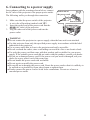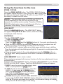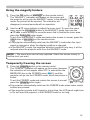
1
IN5542/IN5542c/IN5544/IN5544c User's Manual (concise) Thank you for purchasing this product. Before using this product, please read through this manual in order to use this product well and safely. NOTE * In this manual, unless any comments are accompanied, “the manuals” means all the documents provided with this product, and “the product” means this projector and all the accessories came with the projector. WARNING ● Read all the manuals before using the product. Keep the manuals in a safe place for future reference. ● Heed all warnings and cautions in the manuals and on the product. ● Follow all the instructions in the manuals and on the product. Contents 1. First of all.............................................2 9. Projecting images..............................16 1.1 Entries and graphical symbols............... 2 1.2 Important safety instructions.................. 2 1.3 Regulatory notices.................................. 3 9.1 Displaying and switching the image.... 16 9.2 Focusing the image.............................. 16 9.3 Zooming the image.............................. 16 9.4 Adjusting the projection position......... 17 9.5 Selecting an aspect ratio....................... 17 9.6 Correcting the keystone distortion....... 17 9.7 Hiding the projection image................. 18 9.8 Temporarily blanking the display......... 18 2. Checking the contents of package.....5 3. Attaching the lens unit........................5 4. Placing the projector...........................6 4.1 Installation environment......................... 6 4.2 Projection style....................................... 6 4.3 Projection distance................................. 7 4.4 Placement............................................... 8 10. Maintenance....................................19 10.1 Lamp unit........................................... 19 10.2 Filter unit............................................ 21 10.3 Internal clock battery.......................... 22 10.4 Others................................................. 22 4.5 Supplementary anti-theft means......8 5. Connecting with your devices............9 6. Connecting to a power supply..........12 7. Preparing the remote control...........13 11. Using the CD manual......................23 12. Specifications...................................24 13. Troubleshooting - Warranty and after service........26 7.1 Putting the batteries.............................. 13 7.2 Transmitting condition......................... 14 7.3 Laser pointer......................................... 14 8. Turning the projector on/off.............15 8.1 Turning on............................................ 15 8.2 Turning off........................................... 15 QR82691 1 ENGLISH Projector 1. First of all 1.1 Entries and graphical symbols explanation The following entries and graphical symbols are used for the manuals and the product as follows, for safety purpose. Please know their meanings beforehand, and heed them. WARNING CAUTION NOTICE This entry warns of a risk of serious personal injury or even death. This entry warns of a risk of personal injury or physical damage. This entry notices of fear of causing trouble. 1.2 Important safety instruction The following instructions are important to safely use the product. Always follow them when handling the product. WARNING ● Never use the product in or after an abnormality (ex. the projector smokes, smells strange, has liquid or an object inside, or is broken, etc.) If an abnormality should occur, unplug the projector immediately. ● Keep the product away from children and pets. ● Do not use the product when there is the possibility of thunder or lightening. ● Unplug the projector from the power outlet if the projector is not used for an extended period of time. ● Do not connect the projector to a power supply when a lens unit is not attached to it. ● Do not open or remove any portion of the product, unless the manuals direct it. For internal maintenance, leave it to your dealer or their service personnel. ● Use only the accessories specified or recommended by the manufacturer. ● Do not modify the projector or its accessories. ● Do not let liquid or other items enter inside the projector. ● Do not let the product get wet. ● Do not shock or apply pressure to this product. - Do not place the product on an unstable surface such as an uneven surface or leaning table. - Do not place the product where it is unstable. Place the projector so that it (even the lens part installed) does not protrude from the surface where the projector is placed on. - Always move the projector with two or more people. Place your hands in the indented handles on the bottom of the projector when carrying the projector. - Remove all the attachments including the power cord and cables, from the projector when carrying the projector. Indented handles - Do not lengthen the elevator feet beyond 30 mm. ● Do not look into the lens and the openings on the projector, while the lamp is on. ● Do not approach the lamp cover or exhaust vents while the projection lamp is on or just after the lamp is turned off since they can be too hot. ● Do not apply the laser beam of the remote control to anything except the screen. 2 1.3 Regulatory notices WARNING : This is a Class A product. In a domestic environment this product may cause radio interference in which case the user may be required to take adequate measures. This device complies with part 15 of the FCC Rules. Operation is subject to the following two conditions: (1) This device may not cause harmful interference, and (2) this device must accept any interference received, including interference that may cause undesired operation. This equipment has been tested and found to comply with the limits for a Class A digital device, pursuant to Part 15 of the FCC Rules. In Canada NOTICE: This Class A digital apparatus complies with Canadian ICES-003. These limits are designed to provide reasonable protection against harmful interference when the equipment is operated in a commercial environment. This equipment generates, uses, and can radiate radio frequency energy and, if not installed and used in accordance with the instruction manual, may cause harmful interference to radio communications. Operation of this equipment in a residential area is likely to case harmful interference in which case the user will be required to correct the interference at his own expense. Some cables have to be used with a ferrite core set. Use the accessory cable or a designated type cable for the connection. For cables that have a core only at one end, connect the ferrite core to the projector. CAUTION: Changes or modifications not expressly approved by the party responsible for compliance could void the user’s authority to operate the equipment. 3 ENGLISH About Electro-Magnetic Interference 1.3 Regulatory notices (continued) About Waste Electrical and Electronic Equipment The mark is in compliance with the Waste Electrical and Electronic Equipment Directive 2002/96/EC (WEEE). The mark indicates the requirement NOT to dispose the equipment including any spent or discarded batteries or accumulators as unsorted municipal waste, but use the return and collection systems available. If the batteries or accumulators included with this equipment, display the chemical symbol Hg, Cd, or Pb, then it means that the battery has a heavy metal content of more than 0.0005% Mercury or more than, 0.002% Cadmium, or more than 0.004% Lead. 4 2. Checking the contents of package Soon after purchasing this product, check that all the following items are included in the package. If any items are missing, contact your dealer immediately. (4) (2) (5) ENGLISH (1) (1) Projector (2) Lens adapter (3) Hexagon wrench (for installation of the optional lens unit) (4) Power cord (5) Computer cable (6) Remote control (batteries not included) (7) User documentation (3) (6) ER OR LAS CAT INDI CE R UTE MP CO UR ON MY SO EO VID L BY/ ND STA ID ID ID ID (7) ITA DIG 3 1 4 ER LAS 2 NK BLA ER ENT NU ME ET RES R ION SIT TTE EZE PO SHU FRE Y O ECT NIF AUT ASP MAG P Pby ON TON 3 MY BUT OFF 1 4 NE STO 2 KEY FT M ZOO S SHI LEN + US FOC - + - NOTE * This product is supplied without a lens unit, so that you can choose from a range of lenses ( 24) that can meet your requirements. Ask your dealer about purchasing one or more lenses with this product. * Additional accessories or services may be required for your application. We recommend consulting your dealer beforehand. CAUTION ● Keep the original packing materials, and use them correctly when transporting or storing the product. 3. Attaching the lens unit Ask your dealer to help you with lens installation. Removing and attaching the lens unit should only be accomplished by authorized service personnel. WARNING ● Only use the lens unit specified by the manufacturer. ● Removing and attaching the lens unit should only be accomplished by authorized service personnel. ● Read and keep the user’s manual of the lens unit. ● Be extremely cautious and do not drop or hit the lens against anything. ● Do not transport the projector with the lens attached. CAUTION ● Keep the original packing materials for the lens unit, and use them correctly when transporting or storing the lens unit. NOTICE ● Do not touch the lens surface directly. ● Keep the dust protector of the projector, and use it when no lens unit is attached to the projector. 5 4. Placing the projector Read this chapter through first. Then install the projector into place. 4.1 Installation environment This product must be installed in a stable, cool and airy location. Check your installation environment in accordance with the following. WARNING ● Do not place the product on an unstable surface surface such as an uneven, tilted, or vibrating location. ● Do not place the product near water - for example, near a bathtub, washbowl, kitchen sink, or laundry tub; in a wet basement, near a swimming pool, beach; or outdoors. CAUTION ● Do not place the product in a dusty, smoky, or humid place - for example, in a passageway, in a smoking space, in a kitchen, or outdoors. ● Do not place the product near heat sources - for example, radiators, heat registers, stoves, or other product (including amplifiers) that produces heat. ● Do not place this product in a magnetic field. NOTICE ● Do not place the product in a place where radio interference may be caused. ● Do not place the projector in a place where any strong light hit the remote sensors. 4.2 Projection style Choose the projection style suitable to your use, referring to the illustration below. (2) Ceiling mount (suspended from a ceiling) (1) Standard style (placed on a table) NOTE * When installing the projector in a special situation such as a ceiling mount, specific mounting accessories ( 24) and service may be required. Before installing the projector, consult your dealer about your installation. WARNING ● Consult with your dealer about installation beforehand. ● Use only the mounting accessories the manufacturer specified, and leave installation and removal of the projector with the mounting accessories to the service personnel. ● Read and keep the mounting accessory’s user manuals used. 6 Refer to the following to arrange the projector and your screen. The values shown in the following table were calculated for the model IN5542/IN5542c with the standard lens unit LENS-068. See the lens unit user’s manual for your specific situation. The values differ for every combination of the projector and the lens unit. * The values shown in the table are calculated for full size screen 1024 x 768. (a) Screens size (diagonal) (b) Projection distance (±10%) (c) Screen height (±10%) when the vertical lens shift is set full upward. (c) up (a) Projector top (c) down Projector bottom (Installation side) (b) (a) Screen size [inch (m)] 4 : 3 screen (b) Projection distance (c) Screen height [m (inch)] [cm (inch)] up min. max. down 40 (1.0) 1.7 (66) 2.3 (89) 60 70 80 90 100 120 150 200 250 300 350 400 500 600 700 (1.5) (1.8) (2.0) (2.3) (2.5) (3.0) (3.8) (5.1) (6.4) (7.6) (8.9) (10.2) (12.7) (15.2) (17.8) 2.6 3.1 3.5 4.0 4.4 5.4 6.7 9.0 11.3 13.6 15.9 18.2 22.8 27.4 32.0 (103) (121) (139) (157) (175) (211) (266) (356) (447) (537) (628) (718) (899) (1081) (1262) 3.5 4.0 4.6 5.2 5.8 7.0 8.8 11.8 14.8 17.8 20.7 23.7 29.7 35.6 41.6 (136) (159) (183) (206) (230) (277) (347) (464) (582) (699) (816) (934) (1168) (1403) (1638) -23 -34 -40 -45 -51 -56 -68 -85 -113 -141 -169 -198 -226 -282 -339 -395 (-9) (-13) (-16) (-18) (-20) (-22) (-27) (-33) (-44) (-56) (-67) (-78) (-89) (-111) (-133) (-156) 84 125 146 167 188 209 251 313 418 522 627 731 835 1044 1253 1462 (33) (49) (58) (66) (74) (82) (99) (123) (164) (206) (247) (288) (329) (411) (493) (576) 16 : 9 screen (b) Projection distance (c) Screen height [m (inch)] [cm (inch)] min. max. down up 1.3 (53) 1.8 (72) 2.1 2.5 2.9 3.2 3.6 4.4 5.5 7.4 9.2 11.1 13.0 14.9 18.6 22.4 26.2 (83) (98) (112) (127) (142) (172) (216) (290) (364) (438) (512) (586) (734) (882) (1030) 2.8 3.3 3.8 4.3 4.7 5.7 7.2 9.6 12.0 14.5 16.9 19.4 24.2 29.1 34.0 (110) (129) (148) (168) (187) (225) (283) (379) (474) (570) (666) (762) (954) (1145) (1337) NOTICE ● Do not use a polarized screen, since it can cause a red image. 7 -33 -49 -58 -66 -74 -82 -99 -123 -164 -206 -247 -288 -329 -411 -493 -576 (-13) (-19) (-23) (-26) (-29) (-32) (-39) (-49) (-65) (-81) (-97) (-113) (-130) (-162) (-194) (-227) 83 124 145 165 186 207 248 310 414 517 620 724 827 1034 1241 1447 (33) (49) (57) (65) (73) (81) (98) (122) (163) (204) (244) (285) (326) (407) (488) (570) ENGLISH 4.3 Projection distance 4.4 Placement Heed the following and install the projector in accordance with the preceding paragraph 4.3. WARNING ● Keep the projector away from anything that could catch fire. ● Do not block or cover the openings on the projector, and keep sufficient space for ventilation around the projector. - Do not use the projector on a cushioned surface such a rug, a carpet or bedding. - Keep the projector away from light-weight materials such as a piece of paper that can stick to the intake holes. ● Do not use the projector on an unstable surface surface such as a cart. ● Place the projector so that nothing enters inside of the projector. - Keep the projector away from small items such as paperclips that can fall into the inside. - Keep the projector away from any liquids that can spill or leak into the product. CAUTION ● Keep the projector away from anything that is heat conductive such as metal. - Do not use the projector on a metallic table. ● Keep the projector away from anything that is susceptible to heat such as some types of plastics. NOTICE ● Place the projector so that there is nothing that blocks the projection light to the screen. ● Avoid exposing the remote sensor directly to strong light. 4.5 Supplementary anti-theft means This projector has a security bar for a commercial anti-theft chain or wire up to 10 mm in diameter, and also the security slot for the Kensington lock. For details, see your security tool manual. NOTE * These will not prevent theft, but will help prevent against theft. WARNING ● Do not use the security slot to prevent the projector from falling, since this is not what it is designed for. CAUTION ● Do not place the anti-theft chain or wire near the projector’s exhaust vents, since the chain or wire heated by the hot exhaust may cause burns. 8 Before connecting the projector to your devices, check the device manual to ensure that the device is compatible with this projector and to check what is required for the connection. Consult your dealer when the required accessory did not come with the product or the accessory is damaged. It may be regulated under some standard. After making sure that the projector and the devices are turned off, perform the connection, according to the following instructions. Refer to the illustrations on subsequent pages. NOTE * For this product, the optional cable cover is available for purchase. To place an order for it, please tell your dealer the part name of it. ( 24) WARNING ● Use only the accessories specified or recommended by manufacturer. Do not modify the projector or its accessories. ● Read and keep the accessory’s user manual. ● Do not connect or disconnect the projector with devices while they are connected to a power supply except when directed by the device manuals. CAUTION ● Some connecting cables may have to have a specific length, or a ferrite core at the end to connect to the projector, under the regulation of electro-magnetic interference. When a ferrite core is attached to the specified cable only at one end, connect to the end with the ferrite core to the projector. ● Be careful not to connect a cable into the wrong port or the wrong way. ● Be careful not to damage the cables. Route the cables so they will not be stepped on or pinched. NOTICE ● Do not turn your device on prior to the projector, except when directed by the device manuals. 9 ENGLISH 5. Connecting with your devices 5. Connecting with your devices (continued) Example of connecting with VCR or DVD players Digital signal input S-VIDEO VIDEO COMPONENT VIDEO OUT OUT Y Cb/Pb Cr/Pr OUT HDMI Video signal input LAN HDMI CONTROL IN DVI-D REMOTE CONTROL OUT CONTROL MONITOR OUT S-VIDEO IN COMPUTER IN1 COMPUTER IN2 OUT VIDEO 1 G/Y R/Cr/Pr BNC B/Cb/Pb H V VIDEO 2 Y Cb/Pb Cr/Pr K Example of connecting with computers Control from the computer RS-232C Computer signal input RGB OUT RGB OUT DVI-D LAN LAN HDMI CONTROL IN DVI-D REMOTE CONTROL OUT CONTROL S-VIDEO MONITOR OUT IN COMPUTER IN1 COMPUTER IN2 OUT VIDEO 1 CAUTION ● For safety, do not connect the LAN port to any network that might have excessive voltage. R/Cr/Pr G/Y Y Cb/Pb Cr/Pr K 10 BNC B/Cb/Pb H V VIDEO 2 RGB OUT 5. Connecting with your devices (continued) Control from the computer Computer signal input RS-232C RGB OUT R LASE ATOR INDIC Y/ON NDB STA MY RCE SOU ER PUT COM O VIDE ID ID TAL DIGI 3 1 ID ID 4 R LASE Wired remote control 2 K BLAN ER ENT U MEN T RESE N ITIO POS TER EZE FRE SHUT O ECT ASP NIFY AUT PbyP MY MAG ON TON 3 BUT 1 OFF 4 NE STO KEY 2 M ZOO US FOC + T S SHIF + LEN - - LAN HDMI CONTROL IN DVI-D REMOTE CONTROL OUT CONTROL S-VIDEO MONITOR OUT IN COMPUTER IN1 COMPUTER IN2 OUT VIDEO 1 R/Cr/Pr Control of another device by RS-232C commands G/Y BNC B/Cb/Pb H V VIDEO 2 Y Cb/Pb Cr/Pr K Redirection of a computer signal input to another display device RGB IN RS-232C Simultaneous remote control of another projector REMOTE CONTROL IN 11 ENGLISH Example of connecting with another projector or a display device 6. Connecting to a power supply In accordance with the warnings shown below, connect the AC inlet of the projector to the proper power outlet. The following walks you through the connection. 1. Make sure that the power switch of the projector is set to the off-position (marked with “O”). 2. Insert the socket end of the power cord into the AC IN (AC inlet) of the projector. 3. Plug the other end of the power cord into the power outlet. Socket end of the power cord AC IN Power switch WARNING ● Do not connect the projector to a power supply when the lens unit is not attached. ● Use this projector from only the specified power supply in accordance with the label indication on the projector. ● Use a power outlet that is close to the projector and easily accessible. ● Do not overload the outlet, since overloading can result in a fire or an electric shock. ● Use only the power cord that came with this product and is suitable for your power supply. If the suitable power cord did not come with this product, consult your dealer. ● Do not use a damaged power cord. If the power cord you need is damaged, ask your dealer for a new power cord of the same type. ● Do not handle the power cord with wet hands. ● Do not repair or modify the power cord. ● Be careful not to damage the power cord. Route the power cord so that it is unlikely to be walked on or pinched by items placed upon or against them. ● Firmly connect the power cord to avoid loose connections. Do not use a loose or unsound power outlet. 12 7. Preparing the remote control 7.1 Putting the batteries The remote control needs two batteries of the following type. Hitachi Maxell or Hitachi Maxell Energy part number AA Alkaline (LR6 or R6P) Batteries not included. The following walks you through loading batteries into the remote control. 1. Remove the battery cover in the back of the remote control. Push lightly the knob of the battery cover while pulling it up. 2. Put the batteries into the battery holder, according to the polarity markings “+” and “-“ inside the holder. 3. Put the battery cover back into place until it clicks. NOTE * If the remote control malfunctions, try replacing the batteries with fresh ones. WARNING ● Be careful not to press the LASER button when loading the batteries. It is dangerous if a laser beam is unintentionally turned on. See the warning in the following paragraph 7.3. ● Be careful of handling batteries, since a battery can cause explosion, cracking or leakage that could result in a fire, injury, or environment pollution. - Use only the specified batteries. Do not use batteries of different types. - When replacing the batteries, replace both of the batteries with new batteries of the same type. Do not use a new battery with a used battery. - Do not use a battery with damage, such as scratches, dents, rust or leakage. - Make sure the plus and minus terminals are correctly aligned when loading a battery. - Do not work on a battery; for example recharging or soldering. - If the remote control is not used for a long period of time, remove the batteries. - Keep batteries in a dark, cool and dry place. Never expose a battery to a fire or water. - Keep batteries away from children and pets. - When a battery leaks, wipe the leakage out well with a waste cloth. If the leakage adhers to your body, immediately rinse it well with water. When a battery leaks in the battery holder, replace the batteries after wiping the leakage out. - Obey the local laws when disposing a battery. 13 ENGLISH Use the remote control that came with the product. Load the batteries into the remote control after reading this chapter through. 7.2 Transmitting condition The remote control works with the remote sensors on the projector using infrared light (Class 1 LED). The remote sensor senses the remote control signals within the range of (to right and left) and about 3 meters from the sensor. Remote sensors NOTE * You can inactivate one or two of the three sensors using the item REMOTE RECEIVE. of the SERVICE menu under the OPTION menu. * When you want to use two or more projectors of this type at the same time and the same place, use the REMOTE ID function. The buttons of ID 1, ID 2, ID 3 and ID 4 on the remote control can name the projector given the same ID number as the button by the item REMOTE ID of the SERVICE menu under the OPTION menu. Remote sensor 30° STANDBY/O N MY SOURCE ID 3 ID 4 LASER ENTER FREEZE ASPECT SHUTTER PbyP MY 1 - VIDEO DIGITAL 30° 3m about OFF ZOOM + - POSITION MAGNIFY ON 4 MENU RESET AUTO BUTTON 3 2 FOCUS + LASER INDICATOR COMPUTER ID 1 ID 2 BLANK KEYSTONE LENS SHIFT NOTICE ● Avoid exposing the remote sensor directly to strong light. ● Do not put anything between the remote control and the remote sensor on the projector, since it may interfere with transmission of the remote control signals. 7.3 Laser pointer While pressing the LASER button, the remote control emits a laser beam and lights the LASER INDICATOR. Use the laser beam as the pointer on the screen. AVOID EXPOSURE- C A U T I O N LASER RADIATIONDO NOT STARE INTO BEAM MAX. OUTPUT: 1mW WAVE LENGTH: 650nm CLASS2 LASER PRODUCT IEC60825-1 :1993 + A1 : 1997 + A2 : 2001 レーザ光 ビームをのぞきこまないでください。 最大出力 1mW 波長 650 n m クラス2レーザ製品 JIS C 6802:1997/98 LASER INDICATOR LASER RADIATION IS EMITTED FROM THIS APERTURE C A U T I O N LASER RADIATION DO NOT STARE INTO BEAM CLASS2 LASER PRODUCT MAX OUTPUT : 1mw WAVE LENGTH : 650nm Laser aperture AVOID EXPOSURE- LASER RADIATION IS EMITTED FROM THIS APERTURE or LA IN SE DI R CA TO R LASER RADIATIONDO NOT STARE INTO BEAM MAX. OUTPUT: 1mW WAVE LENGTH: 650nm CLASS2 LASER PRODUCT LASER RADIATION DO NOT STARE INTO BEAM CLASS2 LASER PRODUCT MAX OUTPUT : 1mw WAVE LENGTH : 650nm IEC60825-1 :2007 EN60825-1:2007 レーザ光 ビームをのぞきこまないでください。 最大出力 1mW 波長 650 n m クラス2レーザ製品 JIS C 6802:2005 LASER button WARNING ● Use the laser beam of the remote control only for the pointer on the screen. Do not apply the laser beam to anything except the screen. - Never hit eyes with the laser beam since the laser beam can injure eyes. - Do not apply the laser beam to anything except the screen. 14 8. Turning the projector on/off 1. Make sure that the power cord is firmly and correctly connected to the projector and the outlet. 2. Press down the side marked “I” on the power switch. The POWER indicator will light up in steady orange. Wait for the buttons to become ready. It may take several seconds. 3. Press the STANDBY/ON button (on the projector or the remote control). The projection lamp will light up and the POWER indicator will begin blinking in green. When the power is completely on, the indicator will stop blinking and light in steady green. Power switch POWER indicator SHUTTER SECURITY LAMP TEMP POWER STANDBY/ON button STANDBY/ON STANDBY/ON button STANDBY/ON 8.2 Turning off 1. Press the STANDBY/ON button on the projector or the remote control. The message “Power off?” will appear on the screen for about 5 seconds. 2. Press the STANDBY/ON button again while the message is shown. The projector lamp will go off, and the POWER indicator will begin blinking in orange. Then the POWER indicator will stop blinking and light in steady orange when lamp cooling is complete. 3. After making sure that the POWER indicator lights in steady orange, and press down the side marked “O” on the power switch. The POWER indicator will go off. NOTE * When the item DIRECT ON of the OPTION menu is set to the ON, and that the projector was turned off by only the power switch without using the STANDBY/ON button, switching the power switch turns the projector automatically. WARNING ● Do not look directly into the lens or the openings on the projector while the lamp is on. ● Do not approach the lamp cover and the exhaust vents for a while after the lamp goes out, since they may be hot and could cause burns. NOTICE ● Do not turn your device on prior to the projector, except when directed by the device manuals. Turn your device off prior to the projector, except when directed by the device manuals. 15 ENGLISH 8.1 Turning on 9. Projecting images The basic operation of this product is shown in this chapter. For details, please refer to the manuals in the CD “User’s Manual (detailed)”( 23). Remote control Control panel STANDBY/ON LASER INDICATOR Cursor buttons STANDBY/ON MY SOURCE COMPUTER VIDEO LENS SHIFT indicator LENS SHIFT button MENU LENS SHIFT COMPUTER ZOOM VIDEO FOCUS DIGITAL SHUTTER COMPUTER button ZOOM button VIDEO button FOCUS button DIGITAL button ID 1 ID 3 DIGITAL ID 2 COMPUTER button VIDEO button DIGITAL button ID 4 BLANK LASER ENTER Cursor buttons ASPECT button MENU FREEZE ASPECT SHUTTER RESET PbyP AUTO POSITION MY BUTTON MAGNIFY 1 3 ON 2 4 OFF FOCUS ZOOM + + - - FOCUS + button FOCUS - button ZOOM + button ZOOM - button KEYSTONE LENS SHIFT KEYSTONE button LENS SHIFT button 9.1 Displaying and switching the image Pressing one of the following buttons (on the control panel or the remote control) calls the picture signal from one of the input ports belonging to the category the button’s name shows. And repeating and pressing the same button changes the port to take in the signal from in the order shown below. (1) COMPUTER button: COMPUTER IN1 COMPUTER IN2 BNC (2) VIDEO button: Component (Y, Cb/Pb, Cr/Pr) S-VIDEO VIDEO 1 VIDEO 2 (3) DIGITAL button: HDMI DVI-D 9.2 Focusing the image (1) On the control panel, press the FOCUS button first, then use the ◄/► cursor buttons to adjust. (2) On the remote control, use the FOCUS +/FOCUS – buttons to adjust. 9.3 Zooming the image (1) On the control panel, press the ZOOM button first, then use the ◄/► cursor buttons to adjust. (2) On the remote control, use the ZOOM +/ZOOM – buttons to adjust. 16 9.4 Adjusting the projection position WARNING ● Do not lengthen the elevator feet more than 30 mm. If the foot is lengthened beyond this limit, it may come off and drop the projector down, possibly causing an injury or damaging the projector. CAUTION ● Do not place the projector with an inclination more than 5 degrees. Leaning the projector beyond this limit could cause malfunction and shorten the life of the projector. ENGLISH Using the elevator feet Lengthening or shortening the length of the elevator feet shifts the projection position and the projection angle. Turn the elevator feet each to adjust their length. max. 30 mm Adjusting the lens position Shifting the lens position shifts the projection position. After pressing the LENS SHIFT button (on the control panel or the remote control), use the cursor buttons to shift the lens position. NOTE * While the lens is moving, the LENS SHIFT indicator (on the control panel) lights up or blinks green. The projector may ignore operation by buttons while moving the lens. * Generally, better images occur when the lens is set to the center. CAUTION ● Do not put your fingers or any other things around the lens. The moving lens could catch them in the space around the lens and result in an injury. 9.5 Selecting an aspect ratio Use the ASPECT button (on the remote control). Each time you press the button, it changes the aspect ratio of the image in turn. 9.6 Correcting the keystone distortion Pressing the KEYSTONE button (on the remote control) displays the KEYSTONE dialog. Use the cursor buttons according to the dialog, checking the image. 17 Remote control Control panel STANDBY/ON LASER INDICATOR Cursor buttons BLANK button STANDBY/ON MY SOURCE COMPUTER VIDEO ID 1 ID 3 ID 2 ID 4 DIGITAL BLANK LASER MENU ENTER LENS SHIFT COMPUTER ZOOM VIDEO FOCUS DIGITAL SHUTTER SHUTTER indicator SHUTTER button MENU FREEZE ASPECT SHUTTER RESET PbyP AUTO POSITION MY BUTTON MAGNIFY 1 3 ON 2 4 OFF FOCUS ZOOM + + KEYSTONE LENS SHIFT - - 9.7 Hiding the projection image Closing the mechanical lens shutter blocks the projection light and blackens the screen. If you use another monitor device, you can operate the display, hiding it from the audience. Press the SHUTTER button (on the control panel or the remote control) to close, or open the lens shutter. NOTE * While the lens shutter is closed, the SHUTTER indicator (on the control panel) blinks yellow. * Even if the projector is turned off with the lens shutter closed, turning the projector on opens automatically the lens shutter. WARNING ● Do not leave the shutter closed for long periods of time during projector use, since the closed lens shutter could raise the inside temperature, and result in a fire. 9.8 Temporarily blanking the display Using the BLANK button, you can display the BLANK image preset by the item BLANK of the SCREEN menu instead of the input signal image. Press the BLANK button (on the remote control), to display the BLANK image, or recover the input signal image. NOTE * Some projector operations may recover the input signal image automatically. 18 10. Maintenance 10.1 Lamp unit A worn out lamp bulb could burn or burst. It is recommended to keep a spare lamp unit on hand and to replace the lamp unit when the projected image darkens or color reproduction becomes poor. To purchase a spare, contact your dealer and tell the following type number. Optional lamp part number: SP-LAMP-079 If the projector is installed in a special state such as ceiling mount, or if the lamp bulb has broken, also ask the dealer to replace the lamp unit. Otherwise, follow the procedure shown below to replace the lamp unit. 1. Make sure that the projector is unplugged and cooled down. 2. Loosen the screw (marked by arrow) of the lamp cover. Then slide and take it off. 3. Loosen the 3 screws (marked by arrow) of the lamp unit. Then picking the handles of the unit, gently take it from the projector. 4. Gently set the new lamp unit into place. Then retighten the screws of the lamp unit. 5. Put the lamp cover back into place, and retighten the screw of the lamp cover. 6. Reset the LAMP TIME value. (1) Turn the projector on. (2) To display the ADVANCED MENU, press the MENU button (on the control panel or the remote control). On the EASY MENU, select the “ADVANCED MENU” using the ▲/▼ cursor buttons, then press the ► cursor button. (3) To select the OPTION menu, select the “OPTION” using the ▲/▼ cursor buttons in the left column, then press the ► cursor button. (4) To display the LAMP TIME dialog, select the “LAMP TIME” using the ▲/▼ cursor buttons in the right column, then press the ► cursor button. (5) Use the ► cursor button according to the dialog, Selecting “OK” resets the LAMP TIME value. Lamp cover Lamp unit Handles NOTE * The value shown on the OPTION menu as the LAMP TIME is the amount of usage which has occurred since the last time the LAMP TIME was reset. Refer to the value for proper maintenance. NOTICE ● Be sure to reset the LAMP TIME after you have replaced the lamp unit. 19 ENGLISH Before maintaining the projector, be sure to turn off, unplug, and cool it down. Especially when maintaining the lamp, allow the projector to cool for about 45 minutes. WARNING HIGH VOLTAGE HIGH TEMPERATURE HIGH PRESSURE ● The projector uses a high-pressure mercury glass lamp. The lamp can break with a loud bang, or burn out, if jolted or scratched, handled while hot, or worn over time. Note that each lamp has a different lifetime, and some may burst or burn out soon after you start using them. In addition, when the bulb bursts, it is possible for shards of glass to fly into the lamp housing, and for gas containing mercury to escape from the projector’s vent holes. ● About lamp disposal: This product contains a mercury lamp; do not put it in a trash. Dispose of it in accordance with environmental laws. - For lamp recycling, go to www.lamprecycle.org (in the US). - For product disposal, contact your local government agency or www.eiae.org (in the US) or www.epsc.ca (in Canada). For more information, call your dealer. ● If the lamp should break (it will make a loud bang when it does), unplug the power cord from the outlet, and make sure to request a replacement lamp from your local dealer. Note that shards of glass could damage the inside of the projector, or cause injury during handling, so please do not try to clean the projector or replace the lamp yourself. Disconnect the plug from the ● If the lamp should break (it will make a loud bang when it does), ventilate the room well, and make sure not to breathe the gas that power outlet comes out of the projector vents, or get it in your eyes or mouth. ● Before replacing the lamp, turn the projector off and unplug the power cord, then wait at least 45 minutes for the lamp to cool sufficiently. Handling the lamp while hot can cause burns, as well as damaging the lamp. ● Never unscrew except the appointed (marked by an arrow) screws. ● Do not open the lamp cover while the projector is suspended from a ceiling. This is dangerous, since if the lamp’s bulb has broken, the shards will fall out when the cover is opened. In addition, working in high places is dangerous, so ask your local dealer to have the lamp replaced even if the bulb is not broken. ● Do not use the projector with the lamp cover removed. When replacing the lamp, make sure that the screws are screwed in firmly. Loose screws could result in damage or injury. ● Use only the specified lamp type. ● If the lamp breaks soon after the first time it is used, it is possible that there are electrical problems elsewhere besides the lamp. If this happens, contact your local dealer or a service representative. ● Handle with care: jolting or scratching could cause the lamp bulb to burst during use. ● Using the lamp for long periods of time, could cause it to darken, not to light up or to burst. When the pictures appear dark, or when the color tone is poor, please replace the lamp as soon as possible. Do not use old (used) lamps; this is a cause of breakage. 20 To keep the interior venting properly, keep a spare and replace the filter unit periodically, although frequent replacement is not needed for this product. To purchase a spare, contact your dealer and tell the following type number. Optional filter part number: SP-FILTER-01 The following walks you through the steps to replace the filter unit. 1. Make sure that the projector is unplugged and cooled down. 2. Use a vacuum cleaner on and around the filter cover. 3. Pick and pull up the filter cover knobs to take it off. 4. Pinch and pull out the filter unit knobs to take it off. 5. Use a vacuum cleaner on and around the intake vents of the projector. 6. Set the new filter unit into the place. 7. Put the filter cover back into the place. 8. Reset the FILTER TIME value. (1) Turn the projector on. (2) To display the EASY MENU, press the MENU button (on the control panel or the remote control). On the ADVANCED MENU, select the “EASY MENU” using the ▲/▼ cursor buttons in the left column, then press the ► cursor button. (3) To display the FILTER TIME dialog, select the “FILTER TIME” using the ▲/▼ cursor buttons, then press the ► cursor button. (4) Use the ► cursor button according to the dialog, Selecting “OK” resets the FILTER TIME value. Filter cover Filter cover knob Filter unit knob Intake vents NOTE * The value shown on the EASY MENU as the FILTER TIME is the amount of usage which has occurred since the last time the FILTER TIME was reset. Refer to the value for proper maintenance. * You can use the message function, which is set up by the item FILTER TIME of the OPTION menu, to notify you when to replace the lamp. WARNING ● Before checking or replacing the filter unit, turn off, unplug, and cool down the projector. ● To keep ventilation of the inside normal, replace the filter unit periodically. ● Use only the manufacturer specified type of the filter unit. NOTICE ● Be sure to reset the FILTER TIME after you have replaced the filter unit. 21 ENGLISH 10.2 Filter unit 10.3 Internal clock battery This projector can be loaded with a battery for the internal clock that the network function needs. When the clock does not work correctly, ask your dealer to check the battery and to replace if needed. For replacement, prepare a new battery of the following type. You can buy it at the store or order it from your dealer. Hitachi Maxell or Hitachi Maxell Energy part Number CR2032 or CR2032H (Battery not included.) WARNING ● Be careful when handling the battery since it can explode, crack or leak possibly resulting in a fire, injury or environmental pollution. - Use only the specified battery. - When replacing the battery, replace it with a new battery. - Do not use a battery with damage, such as scratches, dents, rust or leakage. - Do not work on a battery; for example recharging or soldering. - Keep a battery in a dark, cool and dry place. Never expose a battery to a fire or water. - Keep a battery away from children and pets. Be careful not to let them swallow a battery. - When a battery leaks, wipe the leakage out well with a waste cloth. If the leakage adhers to your body, immediately rinse it well with water. When a battery leaks in the battery holder, replace the batteries after wiping the leakage out. - Obey the local laws when disposing batteries. 10.4 Others For the lens Be careful not to scratch, crack, dirty, or fog the lens surface, since it affects the image quality. When the lens surface is fogged or dirty, gently wipe it only with the commercial cloth or paper lens cleaner. For the inside of the projector In order to ensure the safe use of your projector, please have it cleaned and inspected by your dealer about once every year. For the cabinet of the projector and remote control For the dirty cabinet of the projector or remote control, use soft cloth. Dip a soft cloth in water or a neutral cleaner diluted in water, and wipe the cabinet lightly after wringing it well. Then, wipe again lightly with a soft and dry cloth. WARNING ● Before checking or cleaning the lens, turn off, unplug, and cool down the projector. ● Do not scratch the projector and knock it against something. Use special caution with the lens surface. ● Do not let the product get wet. Do not let any liquids enter the inside. Do not use a spray. NOTICE ● Do not directly touch the lens surface with hands. ● Do not use cleaners or chemicals other than those specified in this manual. 22 The detailed manuals for this product are on the CD titled “User’s Manual (detailed)” which came with this product. Before using the CD, read the following to ensure the proper use. System requirements For using the CD manual, the following system is required. Windows®: OS:Microsoft® Windows® 98, Windows® 98SE, Windows NT® 4.0, Windows® Me, Windows® 2000/Windows® XP, or the later CPU: Pentium® processor 133MHz / Memory: 32MB or more Macintosh®: OS: Mac OS® 10.2 or the later CPU: PowerPC® / Memory: 32MB or more CD-ROM drive: 4x CD-ROM drive Display: 256 color / 640x480 dots resolution Applications: Microsoft® Internet Explorer® 4.0 and Adobe® Acrobat® Reader® 4.0 or the later How to use the CD 1. Insert the CD into the CD-ROM drive of your computer. 2. When using it on the Macintosh® system, start the web browser by the following. (1) Double-click on the “Projectors” icon displayed on the computer’s desktop. (2) Then click on the “main.html” file. When using it on the Windows® system, the web browser automatically starts. 3. The web browser displays the initial window of the manual. On the window, select the model name of your projector, and the language you want to read the manuals with. The manual in the selected language will open. NOTE * The information in the CD is subject to change without notice. * The manufacturer assumes no responsibility for any obstacle and defect to hardware and software of your computer as a result of the use of the CD. * The reproduction, transfer or copy of all or any part of the information in the CD is not permitted without express written consent. CAUTION ● Only use the CD in a computer’s CD drive. Never insert the CD into a CD drive of a non-computer device such as an audio device. Inserting the CD into an incompatible CD drive may produce a loud noise, which may result in damage to ears and speakers. ● While the CD is not used, put it into its envelope. Avoiding the CD from direct rays, a high temperature, and high humidity. Be careful not to scratch or press the CD. 23 ENGLISH 11. Using the CD manual 12. Specifications The general specifications of this product are shown below. Item Product name Specifications Liquid crystal projector TFT active matrix drive system Liquid crystal panel IN5542/ IN5542c 3.3 cm (1.3 type), 786,432 pixels (1024 horizontal x 768 vertical) IN5544/ IN5544c 3.1 cm (1.22type), 1,092,800 pixels (1366 horizontal x 800 vertical) Lamp 350 W UHB Power supply AC 110-120V/6.0A, AC 220-240V/3.1A Power consumption 540W Temperature range 5 to 35°C (Operating) Ports HDMI.......................................................................... HDMI port x1 DVI-D..........................................................................DVI-D port x1 LAN................................................................................RJ45 port x1 MONITOR OUT......................................D-sub 15 pin mini port x1 CONTROL IN................................................... D-sub 9 pin plug x1 CONTROL OUT............................................... D-sub 9 pin plug x1 REMOTE CONTROL IN............................. 3.5 stereo mini port x1 REMOTE CONTROL OUT........................ 3.5 stereo mini port x1 S-VIDEO...................................................... DIN 4 pin mini port x1 VIDEO 1........................................................................RCA port x1 VIDEO 2........................................................................BNC port x1 COMPUTER IN1....................................D-sub 15 pin mini port x1 COMPUTER IN2....................................D-sub 15 pin mini port x1 BNC (R/Cr/Pr, G/Y, B/Cb/Pb, H, V)..........................BNC port x5 Component (Y, Cb/Pb, Cr/Pr)..................................RCA port x3 Weight (mass) 13.1 kg approx. Size 476 (W) x 272 (H) x 469 (D) mm approx. * See the drawing below. Optional parts Lens unit LENS-067 (Ultra short throw lens) LENS-066 (Short throw lens) LENS-065 (Short throw lens) LENS-068 (Standard lens) LENS-062 (Standard lens) LENS-064 (Long throw lens) LENS-063 (Ultra long throw lens) Lamp unit SP-LAMP-079 Filter unit SP-FILTER-01 Cable cover SP-COVER-01 Lens adapter unit SP-LENS-ADPT-01 24 I 469 O ENGLISH 12. Specifications (continued) 272 476 [unit: mm] 25 13. Troubleshooting – Warranty and after service If an abnormality (ex. the projector smokes, smells strange, is broken or has liquid or an object inside) should occur with this product, stop using the projector immediately. After ensuring that there is no emergency, ask your dealer to check and repair the product. If an abnormality has not occured, please refer to the “Troubleshooting” section of the Operating Guide on the CD first. It may help you resolve the problem. If it does not resolve the problem, consult your dealer. The dealer or the service company that is designated by your dealer will tell you if the product is under warranty. The latest information for this product can be found on the website: www.infocus.com/support ************************************************************************ NOTE * The information in the manuals is subject to change without notice. * The manufacturer assumes no responsibility for any errors that may appear in the manuals. * The reproduction, transfer or copy of all or any part of the manuals is not permitted without express written consent. Trademark acknowledgment All the trademarks are the properties of their respective owners. According to the indication on the official site of each company, we describe as follows. - Macintosh® and Mac OS® are registered trademark of Apple Inc. - Pentium® is registered trademark of Intel Corp. - Microsoft® and Internet Explorer®, Windows®, Windows NT® are registered trademarks of Microsoft Corporation in the U.S. and/or other countries. - Adobe® and Acrobat®, Reader® are registered trademarks of Adobe System Incorporated. - PowerPC® is a registered trademark of International Business Machines Corporation. - DVI is a trademark of Digital Display Working Group. - HDMI, the HDMI logo and High-Definition Multimedia Interface are trademarks or registered trademarks of HDMI Licensing LLC. 26 Projector IN5542/IN5542c/IN5544/IN5544c User's Manual (detailed) – Operating Guide Thank you for purchasing this projector. WARNING ►Before using this product, please read the "User's Manual (concise)" and related manuals to ensure the proper use of this product. After reading them, store them in a safe place for future reference. About this manual Various symbols are used in this manual. The meanings of these symbols are described below. WARNING This entry warns of a risk of serious personal injury or even death. CAUTION This entry warns of a risk of personal injury or physical damage. NOTICE This entry notices of fear of causing trouble. Please refer to the pages written following this symbol. NOTE • The information in this manual is subject to change without notice. • The manufacturer assumes no responsibility for any errors that may appear in this manual. • The reproduction, transfer or copy of all or any part of this document is not permitted without express written consent. Trademark acknowledgment • Windows® is a registered trademark of Microsoft Corporation in the U.S. and/or other countries. • VESA and DDC are trademarks of the Video Electronics Standard Association. • Mac® is a registered trademark of Apple Inc. • DVI is a trademark of Digital Display Working Group. • HDMI, the HDMI logo and High-Definition Multimedia Interface are trademarks or registered trademarks of HDMI Licensing LLC. • Trademark PJLink is a trademark applied for trademark rights in Japan, the United States of America and other countries and areas. All other trademarks are the properties of their respective owners. DN02551 1 Contents Contents About this manual. . . . . . . . . . . 1 Contents . . . . . . . . . . . . . . . . . . 2 Introduction . . . . . . . . . . . . . . . 3 Projector features. . . . . . . . . . . . . . . . 3 Important safety instruction (for the moving). . . . . . . . . . . . . . . . . . . . . . . . 3 Checking the contents of package. . . 4 Attaching the lens unit. . . . . . . . . . . . . 4 Part names . . . . . . . . . . . . . . . . 5 Projector. . . . . . . . . . . . . . . . . . . . . . . 5 Control panel. . . . . . . . . . . . . . . . . . . . 6 Indicator lamp. . . . . . . . . . . . . . . . . . . 6 Rear panel . . . . . . . . . . . . . . . . . . . . . 6 Remote control. . . . . . . . . . . . . . . . . . 7 Setting up . . . . . . . . . . . . . . . . . 8 Installation environment . . . . . . . . . . . 8 Projection style. . . . . . . . . . . . . . . . . . 8 Projection distance. . . . . . . . . . . . . . . 9 Placement. . . . . . . . . . . . . . . . . . . . . 10 Supplementary anti-theft means. . . . 10 Connecting with your devices. . . . . . 11 Connecting power supply. . . . . . . . . 15 Remote control. . . . . . . . . . . . 16 Putting batteries . . . . . . . . . . . . . . . . 16 Transmitting condition. . . . . . . . . . . . 17 Changing the frequency of remote control signal. . . . . . . . . . . . . . . . . . . 17 Using the REMOTE ID function . . . . 18 Using as a wired remote control. . . . 18 Laser pointer. . . . . . . . . . . . . . . . . . . 18 Operating . . . . . . . . . . . . . . . . 19 Turning on. . . . . . . . . . . . . . . . . . . . . 19 Turning off. . . . . . . . . . . . . . . . . . . . . 20 Using the elevator feet . . . . . . . . . . . 20 Using the functions for the lens. . . . . 21 Displaying and switching the image. 22 Selecting an aspect ratio. . . . . . . . . . 23 Using the automatic adjustment feature. . . 23 Adjusting the position. . . . . . . . . . . . 24 Correcting the keystone distortion. . . . 24 Using the magnify feature. . . . . . . . . 25 Temporarily freezing the screen. . . . 25 Temporarily blanking the screen. . . . 26 Temporarily shutting the screen . . . . 26 P by P (Picture by Picture) . . . . . . . . 27 Using the menu function . . . . . . . . . 28 2 EASY MENU. . . . . . . . . . . . . . . 29 Aspect, Auto keystone, Keystone, Keystone, Picture mode, Eco mode, Mirror, Reset, Filter time, Language, Advanced menu, Exit PICTURE menu . . . . . . . . . . . . 31 Brightness, Contrast, Gamma, Color temp, Color, Tint, Sharpness, Active iris, My memory IMAGE menu. . . . . . . . . . . . . . 34 Aspect, Over scan, V position, H position, H phase, H size, Auto adjust execute INPUT menu . . . . . . . . . . . . . . 36 Progressive, Video nr, 3d-ycs, Color space, Component, Video format, Digital fomat, Digital range, Computer in, Frame lock, Resolution SETUP menu. . . . . . . . . . . . . . 40 Auto keystone, Keystone, Keystone, Eco mode, Mirror, Monitor out SCREEN menu. . . . . . . . . . . . . 42 Language, Menu position, Blank, Start up, MyScreen, MyScreen Lock, Message, Source name,Template, C.c. OPTION menu. . . . . . . . . . . . . 47 Source skip, Auto search, Auto keystone, Direct on, Auto off, Sutter timer Lamp time, Filter time, My button, My source, Service NETWORK menu. . . . . . . . . . . 56 Setup, Projector name, My image, Information, Service SECURITY menu . . . . . . . . . . . 61 Enter password, Security password, MyScreen password, Pin lock, Transition detector, My text password, My text display, My text writing Maintenance. . . . . . . . . . . . . . 67 Lamp unit . . . . . . . . . . . . . . . . . . . . . 67 Filter unit. . . . . . . . . . . . . . . . . . . . . . 69 Internal clock battery. . . . . . . . . . . . . 70 Others. . . . . . . . . . . . . . . . . . . . . . . . 70 Troubleshooting . . . . . . . . . . . 71 Related messages . . . . . . . . . . . . . . 71 Regarding the indicator lights. . . . . . 72 Phenomena that may be easily mistaken for machine defects. . . . . . . 74 Warranty and after-service. . . 77 Specifications. . . . . . . . . . . . . 77 Introduction Introduction Projector features This projector can project various picture signals onto a screen. This projector requires only a minimal installation space and can produce a large projected image from a very short distance. In addition, the projector has the following features to allow for many different installation applications. ü The HDMI port can support a variety of image equipment which has a digital interface to get clearer images on a screen. ü T he super bright lamp and high quality optical system can fulfill the demands of professional uses. ü T he selectable optional lens units and the super wide range of the lens shift feature will give you the ability to install the product wherever you want. ü T he lens shutter can hide the interior of the projector and help your presentation. ü T he wealth of I/O ports is believed to support any business application. ü T his projector's network supports the PJLinkTM standard. ü P JLinkTM is a unified standard for operating and controlling data projectors. PJLinkTM enables central control of projectors manufactured by different vendors and projectors can be operated by a controller. PJLinkTM compliant equipment can be managed and controlled at any time and in any place, regardless of manufacturer. For the command of PJLinkTM, see &User's Manual (Technical) For specifications of PJLinkTM, see the website of the Japan Business Machine and Information System Industries Association. URL: http://pjlink.jbmia.or.jp ü T he unique Electric Dust Catcher Air filter system is expected to prevent air dust from getting into the projector and reduces the frequency of maintenance events. Important safety instruction (for moving) *For details, see the & User's Manual (concise). WARNING ►Always move the projector with two or more people. Place your hands in the indented handles on the bottom of the projector when carrying the projector. ►Remove all the attachments including the power cord and cables, from the projector when carrying the projector. Indented handles 3 Introduction Checking the contents of package Soon after purchasing this product, verify that all the following items are included in the package. If any items are missing, contact your dealer immediately. (1) Projector (2) Lens adapter (3) Hexagon wrench (for installation of the optional lens unit) (4) Power cord (5) Computer cable (6) Remote control (batteries not included) (7) User’s documentation (1) (2) (3) LASER INDICATOR STANDBY/ON MY SOURCE COMPUTER (4) (5) (6) VIDEO ID 1 ID 3 ID 2 ID 4 DIGITAL BLANK LASER ENTER FREEZE MENU ASPECT SHUTTER PbyP AUTO MY BUTTON RESET POSITION MAGNIFY 1 3 ON 2 4 OFF FOCUS ZOOM + + - - KEYSTONE LENS SHIFT (7) NOTE • This product is supplied without a lens unit so that you can choose from a range of lenses (&77) that can meet your requirements. Ask your dealer for details, and purchase one or more lenses with this product. • Some additional accessories or services may be required for your application. We recommend that you consult your dealer beforehand. CAUTION ►Keep the original packing materials, and use them correctly when transporting or storing the product. Attaching the lens unit Ask your dealer to help you with lens installation. Removing and attaching the lens unit should only be accomplished by authorized service personnel. WARNING ►Only use the lens unit specified by the manufacturer. ►Removing and attaching the lens unit should only be accomplished by authorized service personnel. ►Read and keep the user’s manual of the lens unit. ►Be extremely cautious and do not drop or hit the lens against anything. ►Do not transport the projector with the lens attached. CAUTION Keep the original packing materials for the lens unit, and use them correctly when transporting or storing the lens unit. NOTICE ►Do not touch the lens surface directly. ► Keep the projector's dust protector, and use it when no lens is attached to the projector. 4 Part names Part names Front ring Front cover Projector (1) Dust protector (2) Remote sensors (x 2) (&17) (3) Exhaust vents (4) Filter cover (&69) The filter unit and intake vent are inside. (5) Control panel (&6) (6) Rear panel (&6) (7) Reset switch (&73) (8) Lamp cover (&67) The lamp unit is inside. (9) AC IN (AC inlet) (&15) (10) Power switch (&19,20) (11) Security bar (&10) (12) Security slot (&10) (13) Indented handles (x 2) (&3) (14) Elevator feet (x 2) (&20) (3) (1) See the NOTICE (7) HOT! (2) (8) HOT! (9) (4) (10) (11) (12) (14) (6) (5) (13) WARNING ►HOT! : Do not touch around the lamp cover or the exhaust vents during use or just after use, since it is hot. ►Do not look into the lens or vents while the lamp is on, since the strong light is harmful to your eyes. ►Do not hold the projector by the front cover or front ring since the projector may drop. ►Do not handle the elevator feet without holding the projector, since the projector may drop down. CAUTION ►Maintain normal ventilation to prevent the projector from heating up. Do not cover, block or plug up the vents. Do not place anything by the intake vents which can stick to or be sucked into the vents. Clean the air filter periodically. NOTICE ►Do not touch the lens surface directly. ► Keep the dust protector of the projector, and use it when no lens unit is attached to the projector. 5 Part names Control panel (1) STANDBY/ON button (&19,20) (2) Cursor buttons ( ▲/▼/◄/► ) (&28) (3) MENU button (&28) (4) COMPUTER button (&22) (5) VIDEO button (&22) The indicator (6) DIGITAL button (&22) (7) LENS SHIFT button (&21) will light green (8) ZOOM button (&21) when the (9) FOCUS button (&21) OSD menu is (10) SHUTTER button (&26) displayed. (1) STANDBY/ON (2) (3) The (4) selected input port's (5) indicator will (6) light green. MENU (7) LENS SHIFT (8) ZOOM (9) FOCUS COMPUTER VIDEO DIGITAL (10) SHUTTER The indicator will blink in yellow when the lens shutter is closed. Indicator lamp (&72) (1) POWER indicator (2) TEMP indicator (3) LAMP indicator (4) SECURITY indicator (5) SHUTTER indicator (1) (2) (3) (4) (5) POWER TEMP LAMP SECURITY SHUTTER Rear panel(&10) (1) HDMI input (2) DVI-D input (3) LAN input (4) MONITOR OUT output (5) CONTROL IN input (6) CONTROL OUT output (7) REMOTE CONTROL IN input (8) REMOTE CONTROL OUT output (9) S-VIDEO input (10) VIDEO 1 input (11) VIDEO 2 input (12) COMPUTER IN1 input (13) COMPUTER IN2 input (14) BNC (G/Y, B/Cb/Pb, R/Cr/Pr, H, V) inputs (15) Component (Y, Cb/Pb, Cr/Pr) inputs (1) (2)(3)(4) (9)(10)(11) LAN HDMI DVI-D CONTROL IN CONTROL OUT REMOTE CONTROL IN S-VIDEO MONITOR OUT COMPUTER IN1 COMPUTER IN2 OUT VIDEO 1 R/Cr/Pr BNC G/Y B/Cb/Pb H V VIDEO 2 Y Cb/Pb Cr/Pr I O AC IN (5) (6) (7) (8) (15) (14) (12) (13) CAUTION ►Only use the reset switch when the projector will not turn off normally, since pushing this switch stops projector operations without cooling it down. 6 Part names Remote control (1) Laser pointer (&18) It is a beam outlet. (2) LASER INDICATOR (&18) (3) LASER button (&18) (4) STANDBY/ON button (&19,20) (5) ID (1-4) button (&18) (6) COMPUTER button (&22) (7) VIDEO button (&22) (8) DIGITAL button (&22) (9) MY SOURCE button (&22) (10) LENS SHIFT button (&21) (11) ZOOM +/- button (&21) (12) FOCUS +/- button (&21) (13) AUTO button (&23) (14) POSITION button (&24) (15) ASPECT button (&23) (16) KEYSTONE button (&24) (17) MAGNIFY ON/OFF button (&25) (18) FREEZE button (&25) (19) BLANK button (&26) (20) SHUTTER button (&26) (21) MY BUTTON (1-4) button (&49) (22) P by P button (&27) (23) MENU button (&28) (24) ENTER button : press the center point. Cursor button: press the point ▲/▼/◄/► (&28). (25) RESET button (&28) (26) Wired remote control output (&18) (27) Battery cover (&16) (28) Battery holder (&16) (27) (29) Frequency switch (&17) (2) (1) LASER INDICATOR (4) (5) (19) STANDBY/ON MY SOURCE COMPUTER ID 1 ID 3 ID 2 ID 4 BLANK (7) DIGITAL (8) ENTER (21) MENU ASPECT SHUTTER RESET PbyP AUTO POSITION MY BUTTON MAGNIFY 1 3 ON 2 4 OFF FOCUS ZOOM KEYSTONE + + - - LENS SHIFT (12) (3) (24) (18) (15) (20) (22) (6) VIDEO LASER FREEZE (9) (23) (25) (13) (14) (17) (16) (10) (11) (26) Back of the remote control (28) (29) WARNING ►Do not look into the beam outlet or point the beam at people or pets while pressing the LASER button, since the beam is harmful to eyes. CAUTION ►Note that the laser beam may result in hazardous radiation exposure. Use the laser pointer only for pointing on the screen. 7 Setting up Setting up Read this chapter through first before installing the projector. Installation environment This product must be installed in a stable, cool and airy location. Check your installation environment in accordance with the following. WARNING ►Do not place the product on an unstable surface surface such as an uneven, tilted, or vibrating location. ►Do not place the product near water - for example, near a bathtub, washbowl, kitchen sink, or laundry tub; in a wet basement, near a swimming pool, beach; or outdoors. CAUTION ►Do not place the product in a dusty, smoky, or humid place for example, in a passageway, in a smoking space, in a kitchen, or outdoors. ►Do not place the product near heat sources - for example, radiators, heat registers, stoves, or other products (including amplifiers) that produce heat. ►Do not place this product in a magnetic field. NOTICE ►Do not place the product in a place where radio interference may be caused. ► Do not place the projector in a place where any strong light can hit the remote sensors. Projection style This projector can be used in the following projection styles. Choose the style suitable to your use. (2) Ceiling mount (suspended from a ceiling) (1) Standard style (placed on a table) NOTE • When mounting the projector in a ceiling mount or upward/downward projection style, specific mounting accessories (&77) and service are required to install the projector. Contact your dealer for more information. If a different projection style is needed, contact your dealer. WARNING ►Consult your dealer about installation beforehand. ►Only use manufacturer approved mounting accessories, and use authorized service personnel to install your projector and mounting accessories 8 Setting up Projection distance Refer to the following to arrange the projector and your screen. The values shown in the following table were calculated for the model IN5542/IN5542c with the standard lens unit LENS-068 that is adjusted to the center position. See the lens unit user's manual for your specific situation. The values differ for every combination of the projector and the lens unit. * The values shown in the table are calculated for a full size screen: 1024×768 (a) Screen size (diagonal) (b) Projection distance (±10%) (c) Screen height (±10%), when the vertical lens shift is set full upward. (b) (a) Projector top (c) up (c) down (a) Screen size [inch (m)] 40 (1.0) 60 70 80 90 100 120 150 200 250 300 350 400 500 600 700 (1.5) (1.8) (2.0) (2.3) (2.5) (3.0) (3.8) (5.1) (6.4) (7.6) (8.9) (10.2) (12.7) (15.2) (17.8) 4 : 3 screen (b) Projection distance (c) Screen height [m (inch)] [cm (inch)] up min. max. down 1.7 (66) 2.3 (89) -23 (-9) 84 (33) 2.6 (103) 3.5 (136) -34 (-13) 125 (49) 3.1 (121) 4.0 (159) -40 (-16) 146 (58) 3.5 (139) 4.6 (183) -45 (-18) 167 (66) 4.0 (157) 5.2 (206) -51 (-20) 188 (74) 4.4 (175 5.8 (230) -56 (-22) 209 (82) 5.4 (211 7.0 (277) -68 (-27) 251 (99) 6.7 (266 8.8 (347) -85 (-33) 313 (123) 9.0 (356 11.8 (464) -113 (-44) 418 (164) 11.3 (447 14.8 (582) -141 (-56) 522 (206) 13.6 (537 17.8 (699) -169 (-67) 627 (247) 15.9 (628 20.7 (816) -198 (-78) 731 (288) 18.2 (718 23.7 (934) -226 (-89) 835 (329) 22.8 (899 29.7 (1168) -282 (-111) 1044 (411) 27.4 (1081 35.6 (1403) -339 (-133) 1253 (493) 32.0 (1262 41.6 (1638) -395 (-156) 1462 (576) Projector bottom (Installation side) 16 : 9 screen (b) Projection distance (c) Screen height [m (inch)] [cm (inch)] min. max. down up 1.3 (53) 1.8 (72) 2.1 2.5 2.9 3.2 3.6 4.4 5.5 7.4 9.2 11.1 13.0 14.9 18.6 22.4 26.2 (83) (98) (112) (127) (142) (172) (216) (290) (364) (438) (512) (586) (734) (882) (1030) 2.8 3.3 3.8 4.3 4.7 5.7 7.2 9.6 12.0 14.5 16.9 19.4 24.2 29.1 34.0 (110) (129) (148) (168) (187) (225) (283) (379) (474) (570) (666) (762) (954) (1145) (1337) -33 -49 -58 -66 -74 -82 -99 -123 -164 -206 -247 -288 -329 -411 -493 -576 (-13) (-19) (-23) (-26) (-29) (-32) (-39) (-49) (-65) (-81) (-97) (-113) (-130) (-162) (-194) (-227) 83 124 145 165 186 207 248 310 414 517 620 724 827 1034 1241 1447 (33) (49) (57) (65) (73) (81) (98) (122) (163) (204) (244) (285) (326) (407) (488) (570) NOTICE ►Do not use a polarized screen, since it can cause a red image. 9 Setting up Placement When installing the projector according to the previous section "Projection distance" (&9) heed the following information WARNING ►Keep the projector away from anything that is easy to catch fire. ►Do not block or cover the openings on the projector, and keep sufficient space for ventilation around the projector. • Do not use the projector on a cushioned surface such a rug, a carpet or bedding. • Keep the projector away from light-weight materials such as a piece of paper that can stick to the intake holes. ►Do not use the projector on an unstable surface surface such as a cart. ►Place the projector so that nothing enters inside of the projector. • Keep the projector away from small items such as paperclips that can fall into the inside. • Keep the projector away from any liquids that can spill or leak into the product. CAUTION ►Keep the projector away from anything that is heat conductive such as metal. • Do not use the projector on a metallic table. ►Keep the projector away from anything that is susceptible to heat such as some types of plastics. NOTICE ►Place the projector so that there is nothing that blocks the projection light to the screen. ► Avoid exposing the remote sensor directly to strong light. Supplementary anti-theft means This projector has a security bar for a commercial antitheft chain or wire up to 10 mm in diameter, and also the security slot for the Kensington lock. For details, see your security tool manual. Security bar Anti-theft chain or wire NOTE • These will not prevent theft, but will help prevent against theft. WARNING ►Do not use the security slot to prevent the projector from falling down, since it is not designed for this purpose. CAUTION ►Do not place the anti-theft chain or wire near the projector’s exhaust vents, since the chain or wire heated by the hot exhaust may cause burns. 10 Security slot Setting up Connecting with your devices Before connecting the projector to your devices, check the device manual to ensure that the device is compatible with this projector and to check what is required for the connection. Consult your dealer when the required accessory did not come with the product or the accessory is damaged. It may be regulated by some standards. After making sure that the projector and the devices are turned off, perform the connection, according to the following instructions. Refer to the illustrations on subsequent pages. NOTE • For this product, the optional cable cover is available for purchase. To place an order for it, please contact your dealer with the part name (&77). WARNING ►Use only the accessories specified or recommended by manufacturer. Do not modify the projector or its accessories. ►Do not connect or disconnect the projector with devices while they are connected to a power supply except when directed by the device manuals. CAUTION ►Some cables may need to be specific lengthes, or have a ferrite core at the end to connect to the projector, under the regulation of electromagnetic interference. When a ferrite core is attached to a specific cable only at one end, connect the end with the ferrite core to the projector. ►Be careful not to put a connector into an incorrect wrong port or in the wrong way. ►Be careful not to damage the cables. Route the cables so they will not be stepped on or pinched. NOTICE ►Do not turn your device on prior to the projector, except when directed by the device manuals. (continued on next page) 11 Setting up Connecting your devices (continued) Example of connecting to VCR or DVD players Digital signal input Video signal input S-VIDEO VIDEO COMPONENT VIDEO OUT OUT Y Cb/Pb Cr/Pr S-VIDEO VIDEOOUT VIDEO COMPONENT OUT OUT Y Cb/Pb Cr/Pr OUT HDMI HDMI LAN LAN DVI-D REMOTE CONTROL OUT CONTROL HDMI HDMI CONTROL IN DVI-D REMOTE IN CONTROL IN CONTROL OUT CONTROL IN MONITOR OUT S-VIDEO MONITOR OUT S-VIDEO COMPUTER IN1 COMPUTER IN2 OUT VIDEO 1 COMPUTER BNC IN1 COMPUTER IN2 OUT VIDEO 1 R/Cr/Pr R/Cr/Pr BNC G/Y B/Cb/Pb G/YY B/Cb/Pb H H V V VIDEO 2 VIDEO 2 Y Cb/Pb Cb/Pb Cr/Pr K Cr/Pr K Example of connecting with computers Control from the computer RS-232C RS-232C Computer signal input RGB OUT RGB OUT DVI-D LAN DVI-D RGB OUT RGB OUT RGB OUT RGB OUT LAN LAN HDMI HDMI R LAN DVI-D REMOTE CONTROL OUT CONTROL CONTROL IN DVI-D REMOTE IN CONTROL IN CONTROL OUT CONTROL IN MONITOR OUT S-VIDEO MONITOR OUT S-VIDEO COMPUTER IN1 COMPUTER IN2 OUT VIDEO 1 COMPUTER BNC IN1 COMPUTER IN2 OUT VIDEO 1 CAUTION ►For safety, do not connect the LAN port to any network that might have excessive voltage. R/Cr/Pr R/Cr/Pr BNC G/Y B/Cb/Pb G/YY B/Cb/Pb H H V V VIDEO 2 VIDEO 2 Y Cb/Pb Cb/Pb Cr/Pr K Cr/Pr K (continued on next page) 12 HD HDMI CO Setting up Connecting your devices (continued) RGB OUT Example of connecting to another projector or display device Computer signal input Control from the computer RS-232C RGB OUT R LASE ATOR INDIC Y/ON NDB STA MY RCE SOU ER PUT COM O VIDE ID ID TAL DIGI 3 1 ID ID 4 R LASE 2 K BLAN ER ENT U MEN T RESE N ITIO POS TER EZE FRE SHUT O ECT ASP NIFY AUT PbyP MY MAG ON TON 3 BUT 1 OFF 4 NE STO KEY 2 M ZOO US FOC + T S SHIF + LEN - Wired remote control - LAN HDMI CONTROL IN DVI-D REMOTE CONTROL OUT CONTROL S-VIDEO MONITOR OUT IN COMPUTER IN1 COMPUTER IN2 OUT VIDEO 1 R/Cr/Pr G/Y BNC B/Cb/Pb H V VIDEO 2 Y Cb/Pb Cr/Pr K Redirecting an RGB input to another display Controlling another device using RS-232C commands RGB IN RS-232C REMOTE CONTROL IN Simultaneous remote control of another projector 13 Setting up Connecting your devices (continued) NOTE • Be sure to read the device manuals before connecting them to the projector, and make sure that all the devices are suitable to be connected with this product. • Before connecting to a PC, check the signal level, signal timing, and resolution. - Be sure to consult with the network administrator. Do not connect LAN port to any network that might have excessive voltage. - Some signals may require an adapter to be input into this projector. - Some PCs have multiple screen display modes which may include some that are not supported by this projector. -A lthough the projector can display signals with resolution up to UXGA (1600X1200), the signal will be converted to the projector’s panel resolution before being displayed. The best display performance will be achieved if the resolutions of the input signal and the projector panel are identical. • When connecting, make sure that the shape of the cable's connector fits the port you are connecting to, and be sure to tighten the screws on connectors with screws. • When connecting a laptop PC to the projector, be sure to activate the PC’s external RGB output. (Set the laptop PC to CRT display or to simultaneous LCD and CRT display.) For details on how this is done, please refer to the PC's instruction manual. • When the picture resolution changes on a computer depending on an input, the automatic adjustment feature may take some time and may not complete successfully. In this case, you may not be able to see a check box to select “Yes/No” for the new resolution on Windows. Then the resolution will go back to the original. It might be recommended to use a different CRT or LCD monitor to change the resolution. • In some cases, this projector may not display a proper picture or display any picture on screen. For example, automatic adjustment may not function correctly with some input signals. Composite sync and sync on G input signals may confuse this projector, so the projector may not display the image properly. • The HDMI and DVI-D ports of this model are compatible with HDCP (High-bandwidth Digital Content Protection) and therefore are capable of displaying a video signal from HDCP compatible DVD players and the like. About Plug-and-Play capability Plug-and-Play is a system composed of a computer, its operating system and peripheral equipment (i.e. display devices). This projector is VESA DDC 2B compatible. Plug-andPlay can be used by connecting this projector to a computer that is VESA DDC (display data channel) compatible. • Take advantage of this feature by connecting an RGB cable to the COMPUTER IN1 port (DDC 2B compatible). Plug-and-Play may not work properly if any other type of connection is attempted. • Please use the standard drivers in your computer as this projector is a Plug-and-Play monitor. NOTE for HDMI • The HDMI supports the following signals. -Video signal : 480i@60,480p@60,576i@50, 576p@50,720p@50/60,1080i@50/60, 1080p@50/60 -PC signals : See User’s Manual (Technical) • This projector can be connected to equipment which have HDMI or DVI connectors, but some equipment may not work with this projector such as not displaying an image. • .Be sure to use an HDMI cable that has the HDMI logo. • When connecting the projector to a device with a DVI connector, use a DVI to HDMI cable to connect to the projector's HDMI port. 14 Setting up Connecting power supply In accordance with the warnings shown below, connect the AC inlet of the projector to the proper power outlet. The following walks you through the connection. Make sure that the power switch of the projector is set to the off-position (marked with “O”). Insert the socket end of the power cord into the AC IN (AC inlet) of the projector. Plug the other end of the power cord into the power outlet. 1. 2. 3. Socket of the power cord AC IN Power switch WARNING ►Do not connect the projector to a power supply when the lens unit is not attached. ►Use this projector from only the specified power supply in accordance with the label indication on the projector. ►Use a power outlet that is close to the projector and easily accessible. ►Do not overload the outlet, since overloading can result in a fire or an electric shock. ►Use only the power cord that came with this product and is suitable for your power supply. If the suitable power cord did not come with this product, consult your dealer. ►Do not use a damaged power cord. If the power cord you need is damaged, ask your dealer for a new power cord of the same type. ►Do not handle the power cord with wet hands. ►Do not repair or modify the power cord. ►Be careful not to damage the power cord. Route the power cord so that it will not be walked on or pinched by items placed upon or against them. ►Firmly connect the power cord to avoid loose connections. Do not use a loose or unsound power outlet. 15 Remote control Remote control Putting batteries The remote control needs two batteries of the following type. Hitachi Maxell or Hitachi Maxell Energy part number AA Alkaline (LR6 or R6P) Batteries not included. The following walks you through loading batteries into the remote control. the battery cover in the back of the 1. Remove remote control. Push lightly the knob of the battery cover while pulling it up. the batteries into the battery holder, according to the 2. Put polarity markings “+” and “-“ inside the holder. 3. Put the battery cover back into place until it clicks. NOTE • If the remote control malfunctions, try replacing the batteries with fresh ones. WARNING ►Be careful not to press the LASER button when loading the batteries. It is dangerous if a laser beam is unintentionally turned on. Please refer to the section "Laser pointer" (&18). ►Be careful when handling batteries, since a battery can explode, crack or leak possibly causing a fire, injury, or environmental pollution. • Use only the specified batteries. Do not use batteries of different types. • When replacing, replace both of the batteries with new batteries of the same type. Do not use a new battery with a used battery. • Do not use a battery with damage, such as scratches, dents, rust or leakage. • Make sure the plus and minus terminals are correctly aligned when loading a battery. • Do not work on a battery; for example recharging or soldering. • If the remote control is not used for a long period of time, remove the batteries. • Keep batteries in a dark, cool and dry place. Never expose a battery to a fire or water. • Keep batteries away from children and pets. • When a battery leaks, wipe the leakage out well with a waste cloth. If the leakage adhers to your body, immediately rinse it well with water. When a battery leaks in the battery holder, replace the batteries after wiping the leakage out. • Obey the local laws when disposing a battery. 16 Remote control Transmitting condition The remote control works with the remote sensors on the projector using infrared light (Class 1 LED). The remote sensor senses the remote control signals within the range of (to right and left) and about 3 meters from the sensor. Remote sensors Remote sensor 30º 30º STANDB Y/ON MY SOURCE COMPUT ID 1 ID 3 ID 2 BLANK LASER INDICATOR ID 4 ER Approx. 3m VIDEO DIGITAL LASER ENTER FREEZE ASPECT SHUTTER PbyP MY 1 POSITIO MAGNIFY ON 4 MENU N OFF ZOOM + - RESET AUTO BUTTON 3 2 FOCUS + - KEYSTO LENS NE SHIFT NOTE • You can inactivate one or two of the three sensors using the item REMOTE RECEIVE in the SERVICE menu under the OPTION menu. • When you want to use two or more projectors of this type simultaneously and the same place, use the REMOTE ID function. The buttons of ID 1, ID 2, ID 3 and ID 4 on the remote control can name the projector given the same ID number as the button by the item REMOTE ID of the SERVICE menu under the OPTION menu. NOTICE ►Avoid exposing the remote sensor directly to strong light. ►Do not put anything between the remote control and the remote sensor on the projector, since it may interfere with transmission of the remote control signals. Changing the frequency of remote control signal Inside of The accessory remote control can be set to mode the battery cover 1 or mode 2 signal frequencies. If the remote control does not function properly, try changing the signal frequency. Please remember to set the “REMOTE FREQ.” in SERVICE item of OPTION menu (&51) of the Frequency switch projector to match the remote control mode. To set the remote control mode, slide the frequency switch knob inside the battery cover into the position indicated by the mode number to choose. 2 1 Back of the remote control 17 Remote control Using the REMOTE ID function This function defines which projector is controlled by the remote control. Utilize this function when you use multiple projectors of the same type simultaneously. STANDBY/ON MY SOURCE COMPUTER Set the ID number to the projector beforehand, VIDEO referring to the item “REMOTE ID” item (&52). ID 1 ID 3 DIGITAL Press a ID button on the remote control. The ID button ID 4 ID 2 selected will light for 3 seconds. LASER INDICATOR 1. 2. BLANK LASER NOTE • Each time you press any button (except ID buttons), the ID button of current selected ID number will light. ENTER • To confirm the projector's current ID, press any ID button for 3 seconds. Its number will be shown on each screen regardless of set ID of projector. FREEZE Using as a wired remote control MENU ASPECT SHUTTER RESET PbyP AUTO POSITION STA NDB Y/O N MY The accessory remote control works as a wired remote control, when the wired control port at the bottom of the remote control is connected to the REMOTE CONTROL port on the back of the projector via a 3.5mm stereo audio cable. This function is useful when a wireless remote signal may not reliably reach the projector. I R COM PUT 1 ID 2 NK LASE INDIC R ATO SOU RCE ID ID BLA ID ER 3 VID EO 4 DIG ITAL LAS ER ENT ER FRE EZE ASP LAN HDMI ECT DVI-D CONTROL IN CONTROL OUT REMOTE CONTROL IN MY BUTTON 1 COMPUTER IN1 COMPUTER IN2 OUT MEN TTER P O BUT ITIO 3 4 + ET POS TON ON 2 FOC U RES AUT MY 1 3 N MAG ON NIFY OFF US ZOO + - BNC VIDEO 1 SHU Pby MAGNIFY MONITOR OUT S-VIDEO M KEY STO NE - LEN S SHI FT R/Cr/Pr 4 OFF FOCUS ZOOM KEYSTONE + + - - 2H V VIDEO 2 G/Y B/Cb/Pb Y Cb/Pb Cr/Pr O AC IN SHIFT NOTE • To connect the remote control with the projector, use an audio LENS cable with 3.5 diameter stereo mini plugs. Laser pointer Instead of using a finger or pointer, the remote control's laser pointer can be used. When the LASER button is pressed, the laser beam and the LASER INDICATOR lights. Laser aperture LASER button AVOID EXPOSURE- LASER RADIATION IS EMITTED FROM THIS APERTURE C A U T I O N LASER RADIATIONDO NOT STARE INTO BEAM MAX. OUTPUT: 1mW WAVE LENGTH: 650nm CLASS2 LASER PRODUCT LASER RADIATION DO NOT STARE INTO BEAM CLASS2 LASER PRODUCT MAX OUTPUT : 1mw WAVE LENGTH : 650nm IEC60825-1 :1993 + A1 : 1997 + A2 : 2001 レーザ光 ビームをのぞきこまないでください。 最大出力 1mW 波長 650 n m クラス2レーザ製品 JIS C 6802:1997/98 R R SE TO LA ICA IND AVOID EXPOSURE- LASER RADIATION IS EMITTED FROM THIS APERTURE C A U T I O N or LASER RADIATIONDO NOT STARE INTO BEAM MAX. OUTPUT: 1mW WAVE LENGTH: 650nm CLASS2 LASER PRODUCT LASER RADIATION DO NOT STARE INTO BEAM CLASS2 LASER PRODUCT MAX OUTPUT : 1mw WAVE LENGTH : 650nm IEC60825-1 :2007 EN60825-1:2007 レーザ光 ビームをのぞきこまないでください。 最大出力 1mW 波長 650 n m クラス2レーザ製品 JIS C 6802:2005 N Y/O DB AN ST MY L ITA 3 DIG ID ID LASER INDICATOR EO VID ID ID ER UT MP CO CE UR SO 1 4 R SE LA 2 K AN BL R TE EN NU ME T RESE TER ZE EE FR SHUT CT ION SIT PO TO PE AS AU MY ON TT BU IFY GN MA yP Pb ON 3 F OF 1 4 2 NE TO YS KE OM ZO S NS + LE CU FO + IFT SH - WARNING ►Only use the remote control's laser beam to point at the screen. Do not point the laser beam at anything except the screen. • Never hit eyes with the laser beam since the laser beam can injure eyes. • Do not point the laser beam at anything except the screen. 18 Operating Operating Turning on The following walks you through the steps to turn the projector on. For other devices, follow the manual of each. Make sure that the power cord is firmly and correctly connected to the projector and the outlet. Power POWER indicator Press down the side marked “I” on the power switch switch. The POWER indicator will light solid orange. Then wait for the buttons to become ready. It may take several seconds. 1. 2. SHUTTER SECURITY LAMP TEMP POWER STANDBY/ON the STANDBY/ON button (on the projector 3. Press or the remote control). The projection lamp will light up and the POWER indicator will begin blinking green. When the power is completely on, the indicator will stop blinking STANDBY/ON button and light solid green. To display the picture, select an input signal according to the section "Displaying and switching the image" (&22). STANDBY/ON NOTE • When the item DIRECT ON of the OPTION menu is set to ON and the projector is turned off using a power switch instead of the STANDBY/ON button, switching the power switch on turns the projector on immediately (unlike the procedure described above). WARNING ►Do not look directly into the lens or the openings on the projector while the lamp is on. ►Do not approach the lamp cover and the exhaust vents, while the projection lamp is on. NOTICE ►Do not turn your device on prior to the projector, except when directed by the device manuals. 19 Operating Turning off The following walks you through the steps to turn the projector off. the STANDBY/ON button on the projector 1. Press or the remote control. The message "Power off?" will appear on the screen for about 5 seconds. 2. Press the STANDBY/ON button again while the message is shown. The projector lamp will go off, and the POWER indicator will begin blinking orange. Then the POWER indicator will stop blinking and light solid orange when lamp cooling is complete. 3. Power switch POWER indicator SHUTTER SECURITY LAMP TEMP POWER STANDBY/ON STANDBY/ON STANDBY/ON button After making sure that the POWER indicator lights solid orange, and press down the side marled “O” on the power switch. The POWER indicator will go off. For other devices, follow the device's manual. NOTE • Use the reset switch only when the projector cannot be turned off by normal procedure. WARNING ►Do not approach the lamp cover and the exhaust vents for a while after the lamp goes out, since they may be hot and could cause burns. NOTICE ►Turn your device off prior to the projector, except when directed by the device manuals. Using the elevator feet Lengthening or shortening the length of the elevator feet shifts the projection position and the projection angle. Turn the elevator feet each to adjust their length 5° max. 30 mm WARNING ►Do not lengthen the elevator feet more than 30 mm. Lengthening the foot beyond this can cause the foot to come off and drop the projector down possibly resulting in an injury or damaging the projector. CAUTION ►Do not place the projector with an inclination of 5 degrees or more. If the projector is inclined more than this, the projector could malfunction and shorten the life of the projector. 20 Operating Using the functions for the lens ZOOM / FOCUS Press the ZOOM / FOCUS button. The ZOOM / FOCUS dialog will appear. Adjust the zoom / focus using the ◄/► button while the dialog is displayed. Press the ▼ button to select "EXIT" on the dialog. It closes the OSD menu. NOTE • The adjustable range of ZOOM and FOCUS varies depending on the lens unit mounted on the projector to maintain picture quality. Therefore ZOOM or FOCUS adjustments may not reach the end of the bar indicators in the dialog. This is not a defect. LENS SHIFT Press the LENS SHIFT button. The LENS SHIFT dialog will appear. Using the ▲/▼/◄/► buttons, while the dialog is displayed, shifts the lens. CENTERING In the LENS SHIFT dialog: Press the DIGITAL button. In the standby mode: Press the LENS SHIFT and the DIGITAL buttons for 3 seconds simultaneously. ● While the lens is shifting, the menu will disappear and an hourglass icon will appear on screen. Lens shifting may take up to one minute. ● The LENS SHIFT indicator lights up or blinks green while the lens is shifting. Then the indicator will stop blinking and light for 3 seconds in a solid green after lens is centered. ●W hen the lens is located in the center already, pressing the DIGITAL button in the LENS SHIFT dialog causes the LENS SHIFT indicator to be solid green for 3 seconds. LENS MEMORY SAVE / LOAD / CLEAR This projector is equipped with memory functions for the lens adjustments (zoom, focus and shift). To display the LENS MEMORY dialog, select the LENS MEMORY on the ZOOM, FOCUS or LENS SHIFT dialog. Then the LENS MEMORY dialog will appear. AVE:To save the current lens adjustment, select S SAVE-(1-3) and press ► or ENTER button. LOAD:To load a saved adjustment, select the LOAD-(1-3) and press ► or ENTER button. When the MY BUTTON button is allocated to the LOAD-(1-3) the memory can be loaded without the LENS MEMORY dialog. CLEAR:Selecting the CLEAR LENS MEMORY in the LENS MEMORY dialog displays the CLEAR LENS MEMORY dialog. Select the number to be cleared using ▲/▼ buttons and press the ► button. A confirmation dialog will display. Then press the ► button again in the dialog. 21 Operating Displaying and switching the image the COMPUTER button to select an input port for the 1. Press RGB signal. Each time you press the button, the projector switches between the RGB input ports as per below. COMPUTER IN1 COMPUTER IN2 BNC LASER INDICATOR STANDBY/ON MY SOURCE COMPUTER VIDEO ID 1 ID 3 DIGITAL ID 4 2 ● While ON is selected for AUTO SEARCH item in OPTION menu,ID the projector will keep checking every port sequentially until an inputBLANKsignal is LASER detected (47). If the COMPUTER button is pushed when VIDEO 1, VIDEO 2, S-VIDEO, Component, HDMI or DVI-D port is selected, the projector will check the COMPUTER IN1 port first. ENTER LASER INDICATOR the VIDEO button to select an input for video signal. 1. Press Each time you press the button, the projector switches its video input port as per below. STANDBY/ON MY SOURCE COMPUTER FREEZE ID 1 ID 3 ASPECT ID 2 SHUTTER ID 4 COMPONENT (Y, Cb/Pb, Cr/Pr) S-VIDEO VIDEO 1 VIDEO 2 AUTO PbyP BLANK VIDEO MENU DIGITAL RESET POSITION LASER MY BUTTON ● While ON is selected for AUTO SEARCH item in OPTION menu, the projector will keep checking every port sequentially until an input signal is detected (47). ENTER If the VIDEO button is pushed when the COMPUTER IN1 or COMPUTER IN2 STANDBY/ON MY SOURCE COMPUTER port is selected, the projector will check the Component port first. MAGNIFY 1 3 ON 2 4 LASER OFF INDICATOR FOCUS 1. Press the DIGITAL button to select an input for the digital signal. Each time you press the button, the projector switches its digital input port as per below. HDMI DVI-D + ZOOM KEYSTONE VIDEO MENU LENS SHIFT DIGITAL SHUTTER RESET ID 4 + FREEZE ID 1 - ASPECT ID 2 ID 3 AUTO PbyP BLANK MY BUTTON 3 1 POSITION LASER MAGNIFY ON ● While ON is selected for AUTO SEARCH item in OPTION menu, the projector ENTER will keep checking every port sequentially until an input signal is detected (47). If the DIGITAL button is pushed when Component, S-VIDEO, VIDEO 1 or KEYSTONE VIDEO 2 port is selected, the projector will check HDMI port first. FREEZE MENU 2 4 FOCUS ZOOM + + OFF LENS SHIFT 1. Press the MY SOURCE button on the remote control. The input signal will change to the signal specified in MY SOURCE(49). ASPECT SHUTTER AUTO PbyP RESET LASER INDICATOR POSITION STANDBY/ON MY SOURCE COMPUTER MY BUTTON 1 3 MAGNIFY ON VIDEO ● This function can also be used for a document camera. Select the input portDIGITAL that ID 4 ID 2 connected the document camera. ID 1 ID 3 2 4 OFF FOCUS ZOOM + + KEYSTONE LASER - - BLANK LENS SHIFT ENTER 22 FREEZE MENU Operating Selecting an aspect ratio the ASPECT button on the remote control. 1. Press Each time you press the button, the projector switches the mode for aspect ratio as per below. For a computer signal NORMAL 4:3 16:9 16:10* LASER INDICATOR * COMPUTER SMALL* NATIVE FULL* STANDBY/ON MY SOURCE For an HDMI or DVI-D signal ID 1 ID 3 NORMAL 4:3 16:9 16:10* 14:9 SMALL* NATIVE* DIGITAL FULL* VIDEO ID 4 ID 2 signal For a video signal, S-video signal or component video BLANK LASER 4:3 16:9 16:10* 14:9 SMALL* NATIVE* FULL* LASER INDICATOR For no signal 4:3 (fixed, except IN5544/IN5544c) / FULL (fixed, IN5544/IN5544c) ● *16:10 / FULL: IN5544/IN5544c only. NATIVE: Except IN5542/IN5542c. SMALL: Except IN5544/IN5544c. ● The NORMAL mode maintains the signal's native aspect ratio. Using the automatic adjustment feature 1. ENTER STANDBY/ON MY SOURCE COMPUTER VIDEO ID 1 ID 3 FREEZE ID 2 ASPECT ID 4 DIGITAL MENU SHUTTER RESET AUTO POSITION BLANK PbyP LASER MY BUTTON MAGNIFY 3 1 ENTER ON Press the AUTO button on the remote control. Pressing this button performs the following. F or a computer signal FREEZE MENU KEYSTONE The vertical position, the horizontal position and the SHUTTER RESET ASPECT LENS SHIFT horizontal phase will be automatically adjusted. AUTO PbyP POSITION Make sure that the application window is set to its maximum size prior to attempting to use this feature. A MY BUTTON dark picture may be incorrectly adjusted. Use a bright picture when adjusting. F or a video signal and S-video signal The video format best suited for the respective input signal will be selected KEYSTONE automatically. This function is available only when the AUTO is selected for LENS SHIFT the VIDEO FORMAT item in the INPUT menu (37). The vertical position and horizontal position will be automatically set to the default. F or a component video signal The vertical position, horizontal position and horizontal phase will be automatically set to the default. ● The automatic adjustment operation requires approx. 10 seconds. Also please note that it may not function correctly with some input. When this function is performed for a video signal, extra items such as a line may appear outside a picture. ● The items adjusted by this function may vary when the FINE or DISABLE is selected for the AUTO ADJUST item of the SERVICE item in the OPTION menu (50). 2 4 FOCUS ZOOM + + - - OFF MAGNIFY 1 3 ON 2 4 OFF FOCUS ZOOM + + - - 23 VIDEO ID 1 ID 3 ID 2 ID 4 DIGITAL Operating Adjusting the position the POSITION button on the remote control when no 1. Press menu is indicated. BLANK LASER LASER INDICATOR STANDBY/ON MY SOURCE COMPUTER ENTER The “POSITION” indication will appear on the screen. VIDEO ID 1 ID 3 Use the ▲/▼/◄/► cursor buttons to adjust the picture position. DIGITAL FREEZE MENU ID 4 ID 2 When you want to reset the operation, press the RESET button on the remote control during the operation. SHUTTER RESET ASPECT BLANK LASER To complete this operation, press the POSITION button AUTO PbyP POSITION again. Even if you do not do anything, the dialog will MY BUTTON automatically disappear after a few seconds. ENTER ●W hen this function is performed on a video signal, S-video signal or component video signal, some items such as an extra-line may appear at outside of the picture. FREEZEsignal of MENU ●W hen this function is performed on a Video, S-Video, or component KEYSTONE 480i/60hz or 576i/50hz, the adjustment range depends on the OVER SCAN SHUTTER RESET ASPECT LENS SHIFT settings in the IMAGE menu (34). Adjustments cannot be made when OVER AUTO PbyP POSITION SCAN is set to 10. 2. MAGNIFY Correcting the keystone distortion 1. 2. 1 3 ON 2 4 OFF FOCUS ZOOM + + - - MY BUTTON 1 3 MAGNIFY ON Press the KEYSTONE button on the remote control. A dialog will appear on the screen to aid you in correcting the distortion. KEYSTONE Use the ▲/▼ cursor buttons to select AUTO or MANUAL LENS SHIFT operation, and press the ► button to perform the following. 1) AUTO executes automatic vertical keystone correction. 2) M ANUAL displays a dialog for keystone correction. Use the ▲/▼ cursor buttons to select the direction to correct ( or ) then use the ◄/► buttons for adjustment. To close the dialog and complete this operation, press the KEYSTONE button again. Even if you don’t do anything, the dialog will automatically disappear after a few seconds. 2 4 FOCUS ZOOM + + - - OFF ● The adjustable range of this function will vary among inputs. For some inputs, this function may not work well. ● When V:INVERT or H&V:INVERT is selected to the MIRROR item in the SETUP menu and the projector screen is inclined or angled downward, this function may not work correctly. ● When the zoom adjustment is set to the TELE (telephoto focus), this function may be excessive. This function should be used when the zoom adjustment is set to the full WIDE (wide-angle focus) whenever possible. ● When the projector is placed on the level (about ±3°), this function may not work. ● When the vertical lens shift is not set fully upward (not set fully downward for the optional lens type LENS-067 only (51)), this function may not work well. ●W hen the horizontal lens shift is not set to the center, this function may not work well. ● This function will be unavailable when Transition Detector is on (64). 24 ENTER Operating Using the magnify feature 1. Press the ON button of MAGNIFY on the remote control. The “MAGNIFY” indication will appear on the screen and the projector will go into the MAGNIFY mode. In the Magnify mode, the picture will be zoomed. The indication will disappear in several seconds with no operation. FREEZE MENU ASPECT SHUTTER RESET PbyP AUTO POSITION MY BUTTON MAGNIFY 1 3 ON 2 4 OFF the ▲/▼ cursor buttons to adjust the zoom level. To move the zoom 2. Use area, press the POSITION button in the MAGNIFY mode, then use the FOCUS ZOOM + + KEYSTONE LENS SHIFT ▲/▼/◄/► cursor buttons to move the area. And to finalize the zoom area, press the POSITION button again. To exit from the MAGNIFY mode and restore the screen to normal, press the OFF button of MAGNIFY on the remote control. ● The projector automatically exits from the MAGNIFY mode when the input signal is changed or when the display condition is changed. ● In the MAGNIFY mode, the keystone distortion condition may vary, it will be restored when the projector exits from the MAGNIFY mode. - - LASER INDICATOR NOTE • The zoom level can be finely adjusted. Watch the screenSTANDBY/ON closely to MY SOURCE COMPUTER find the level you want. VIDEO Temporarily freezing the screen the FREEZE button on the remote control. 1. Press The “FREEZE” indication will appear on the screen (however, the indication will not appear when OFF is selected for the MESSAGE item in the SCREEN menu (45)), and the projector will go into the FREEZE mode, which the picture is frozen. To exit the FREEZE mode and restore the screen to normal, press the FREEZE button again. ID 1 ID 3 ID 2 ID 4 DIGITAL BLANK LASER ENTER FREEZE ASPECT MENU SHUTTER RESET ● The projector automatically exits from the FREEZE mode when PbyP someAUTOcontrol POSITION buttons are pressed. ● If the projector projects a still image for a long time, the LCD panelMY BUTTON might burn in. Do not leave the projector in the FREEZE mode for too long. MAGNIFY 1 3 ON 2 4 OFF FOCUS ZOOM KEYSTONE + + - - LENS SHIFT 25 Operating Temporarily blanking the screen 1. Press the BLANK button on the remote control. The blank screen will be displayed instead of the screen of input signal. Please refer to the BLANK item in SCREEN menu (42). To exit from the blank screen and return to the input signal screen, press the BLANK button again. LASER INDICATOR STANDBY/ON MY SOURCE COMPUTER VIDEO ID 1 ID 3 ID 2 ID 4 DIGITAL BLANK LASER ●T he projector automatically exits from the BLANK mode when some ENTER control buttons are pressed. Temporarily shutting the image 1. FREEZE MENU Pressing the SHUTTER button closes or opens the mechanicalASPECT lens SHUTTER shutter. RESET The closed shutter blocks the projection light, so that it can black out the AUTO PbyP POSITION screen. ● The SHUTTER indicator on the projector blinks while the shutter is closed. MY BUTTON STANDBY/ON MY SOURCE COMPUTER ● The projector will turn off automatically when the time set up by the SHUTTER VIDEO TIMER passes (48). ID 1 ID 3 ● When turning the power off with the STANDBY/ON button (20), the lensDIGITAL ID 4 opening 2 shutter closed opens automatically. If the power supply is stopped IDwhile KEYSTONE or closing the lens shutter, the moving of the lens shutter is stopped too. LENS BLANK LASERSHIFT However, when turning the projector on, the lens shutter closed or incompletely opened opens automatically. LASER INDICATOR MAGNIFY 1 3 ON 2 4 OFF FOCUS ZOOM + + - - ENTER FREEZE MENU ASPECT SHUTTER RESET PbyP AUTO POSITION MY BUTTON MAGNIFY 1 3 ON 2 4 OFF FOCUS ZOOM KEYSTONE + + - - LENS SHIFT 26 LASER INDICATOR STANDBY/ON MY SOURCE COMPUTER VIDEO ID 1 Operating ID 3 DIGITAL PbyP (Picture by Picture) ID 2 ID 4 The PbyP is a function to display two different picture signals on a screen that is BLANK LASER split in two areas for each signal. Some of functions can be used with the same operation as it for the normal mode (not in the PbyP mode). There are some operations available only in the PbyP mode.ENTER Starting the PbyP Press the PbyP button on the remote control to start the PbyP function. To quit the PbyP mode, press the button again. FREEZE MENU ASPECT SHUTTER RESET PbyP AUTO POSITION MY BUTTON MAGNIFY 1 3 ON 2 4 OFF FOCUS ZOOM + + - - Showing the setting information PbyP mode normal mode setting information The setting information is displayed for several seconds when the PbyP function is started. It shows KEYSTONE the input signal information for each area. There also LENS operations SHIFT will be a yellow frame on the area where most of are effective. The information can be displayed using the cursor buttons ▲/▼/◄/► when the setting information is not on the screen. S-Video Video 1 Video 2 COMPUTER IN1 Scart RGB Main Component Sub BNC <signal combination> HDMI Press the COMPUTER, VIDEO or DIGITAL button while in the PbyP mode, the menu to select the input signal will be appeared. Choose a signal using the cursor buttons ▲/▼. If you want to change the signal in the sub area, switch the main area using the cursor buttons ◄/► first. Displaying the same signal on the areas is not allowed. For other combinations of the input signal, refer to the right table. Any combinations marked with X can not be selected. sub area DVI-D Changing the picture input signal main area main area COMPUTER IN2 Most of operations are effective for the main area only. Also the audio input signal paired with the picture input signal for the main area is assigned as the audio output signal. The main area can be changed using the cursor buttons ◄/► when the setting information is on the screen. COMPUTER IN1 Changing the main area 0 0 0 0 0 0 0 0 0 0 0 0 0 0 0 0 0 0 0 0 0 0 0 X 0 X X X X 0 X X X X X 0 X X X 0 X X X X 0 X X COMPUTER IN2 0 BNC 0 0 HDMI 0 0 0 DVI-D 0 0 0 Component 0 0 0 0 0 Scart RGB 0 0 0 X X S-Video 0 0 0 X Video 1 0 0 0 Video 2 0 0 0 X 0 0 0 0 X X X X X X X Using the PbyP SWAP function Press the MY BUTTON assigned the PbyP SWAP (49). The position of the area is exchanged without any setting change. NOTE •For some signals, it may not be displayed correctly in the PbyP mode, even if it can be displayed properly in the normal mode. 27 Operating Using the menu functions LASER INDICATOR This projector has the following menus: PICTURE, IMAGE, INPUT, SETUP, SCREEN, OPTION, NETWORK, SECURITY and EASY MENU. The EASY MENU consists of functions often used, and the other menus are classified into each purpose and brought together in the ADVANCED MENU. Each of these menus is operated using the same methods with the ▲/▼/◄/►, ENTER and RESET buttons. The remote control and projector buttons which share the same name function the same. STANDBY/ON MY SOURCE COMPUTER VIDEO ID 1 ID 3 DIGITAL ID 2 ID 4 BLANK STANDBY/ON LASER ENTER button LASER INDICATOR STANDBY/ON MY SOURCE COMPUTER VIDEO ENTER RESET button LASER ENTER FREEZE FREEZE COMPUTER ID 4 BLANK MENU button LENS SHIFT ID 3 DIGITAL Cursor buttons MENU ID 1 ID 2 ASPECT MENU SHUTTER RESET MENU ASPECT SHUTTER PbyP AUTO MY BUTTON RESET POSITION MAGNIFY 1 3 ON 2 4 OFF FOCUS ZOOM + + - - KEYSTONE LENS SHIFT Start / finish the menu To start the MENU, press the MENU button. The MENU you last used (EASY or ADVANCED) will appear, however EASY MENU will appear if the projector was just powered on. To close the MENU, press the MENU button again. If you want to between the EASY and ADVANCED MENU, select the EASY/ADVANCED MENU on the menu. Indication in OSD (On Screen Display) AUTO PbyP ZOOM POSITION VIDEO FOCUS MY BUTTON DIGITAL MAGNIFY 1 3 ON 2 4 OFF FOCUS ZOOM + + SHUTTER KEYSTONE LENS SHIFT - - The meanings of the general words on the OSD are as follows. Indication EXIT RETURN CANCEL or NO OK or YES Meaning Closes the OSD menu, exactly like pressing the MENU button. Teturns the menu to the previous menu. Cancels the operation in the present menu and returns to the previous menu. Executes the prepared function or shifts the menu to the next menu. NOTE ● If you want to move the menu position, use the ▲/▼/◄/► buttons after pressing the POSITION button. ● Some functions cannot be performed when a certain input port is selected, or when a certain input signal is displayed. ● When you want to reset the operation, press the RESET button on the remote control during the operation. Note that items whose functions are performed simultaneously with operation (ex. LANGUAGE, H PHASE etc.) cannot be reset. ● Even if you do not do anything, the dialog will automatically disappear after about 30 seconds. 28 EASY MENU EASY MENU From the EASY MENU, items shown in the table below can be performed. Select an item using the ▲/▼ cursor buttons on the projector or remote control. Follow the instructions below. Item Description ASPECT Using the ◄/► buttons switches the aspect ratio mode. See the ASPECT item in IMAGE menu (34). AUTO KEYSTONE Using the ► button executes the auto keystone function. See the AUTO KEYSTONE item in SETUP menu (40). KEYSTONE Using the ◄/► buttons corrects the vertical keystone distortion. See the KEYSTONE item in SETUP menu (40). KEYSTONE Using the ◄/► buttons corrects the horizontal keystone distortion. See the KEYSTONE item in SETUP menu (41). Using the ◄/► buttons switches the picture mode. The picture modes are combinations of GAMMA and COLOR TEMP settings. Choose a suitable mode according to the projected source. NORMAL ó CINEMA ó DYNAMIC ó BOARD(BLACK) DAYTIME ó WHITEBOARD ó BOARD(GREEN) PICTURE MODE NORMAL CINEMA DYNAMIC BOARD(BLACK) BOARD(GREEN) WHITEBOARD DAYTIME COLOR TEMP 2 MID 3 LOW 1 HIGH 4 Hi-BRIGHT-1 5 Hi-BRIGHT-2 2 MID 6 Hi-BRIGHT-3 GAMMA 1 DEFAULT 2 DEFAULT 3 DEFAULT 4 DEFAULT 4 DEFAULT 5 DEFAULT 6 DEFAULT • When the combination of GAMMA and COLOR TEMP differs from pre-assigned modes above, the display on the menu for the PICTURE MODE is “CUSTOM”. Please refer to the GAMMA and COLOR TEMP (31, 32) items in PICTURE menu. • When this function is performed, lines or other distiortions may appear. (continued on next page) 29 EASY MENU Item ECO MODE MIRROR RESET Description Using the ◄/► buttons turns off/on the eco mode. See the ECO MODE item in SETUP menu (41). Using the ◄/► buttons switches the mode for mirror status. See the MIRROR item in SETUP menu (41). Resets all of the EASY MENU items except the FILTER TIME and LANGUAGE to factory default settings. A confirmation dialog is displayed. Selecting OK using the ► button performs resetting. FILTER TIME The usage time of the air filter is shown in the menu. Performing this item resets the filter time which counts usage time of the air filter. A confirmation dialog is displayed. Selecting the OK using the ► button performs resetting. See the FILTER TIME item in OPTION menu (48). LANGUAGE Using the ◄/► buttons changes the display language. See the LANGUAGE item in SCREEN menu (42). Press the ► or ENTER button to use the menu of PICTURE, ADVANCED MENU IMAGE, INPUT, SETUP, SCREEN, OPTION, NETWORK or SECURITY. EXIT 30 Press the ◄ or ENTER button to finish the OSD menu. PICTURE menu PICTURE menu From the PICTURE menu, items shown in the table below can be performed. Select an item using the ▲/▼ cursor buttons on the projector or remote control, and press the ► cursor button on the projector or remote control, or the ENTER button on the remote control to execute the item. Follow the instructions below. Item BRIGHTNESS CONTRAST Description Using the ◄/► buttons adjusts the brightness. Dark ó Light Using the ◄/► buttons adjusts the contrast. Weak ó Strong Using the ▲/▼ buttons switches the gamma mode. 3 CUSTOM 1 DEFAULT 1 CUSTOM 2 DEFAULT 2 CUSTOM 3 DEFAULT 6 CUSTOM 6 DEFAULT 5 CUSTOM 5 DEFAULT 4 CUSTOM 4 DEFAULT To adjust CUSTOM GAMMA Selecting a mode whose name includes CUSTOM and then pressing the ► button or the ENTER button displays a dialog to aid you in adjusting the mode. This function is useful when you want to change the brightness of particular tones. Choose an item using the ◄/► buttons, and adjust the level using the ▲/▼ buttons. You can display a test pattern for checking the effect of your adjustment by pressing the ENTER or VIDEO button. Each time you press the ENTER or VIDEO button, the pattern changes as per below. No pattern ð Gray scale of 9 steps Ramp Gray scale of 15 steps The eight equalizing bars correspond to eight tone levels of the test pattern (Gray scale of 9 steps) except the darkest in the left end. If you want to adjust the 2nd tone from left end on the test pattern, use the equalizing adjustment bar “1”. The darkest tone at the left end of the test pattern cannot be controlled with any of equalizing adjustment bar. • When this function is performed, lines or other distortions may appear. (continued on next page) 31 PICTURE menu Item Description Using the ▲/▼ buttons switches the color temperature mode. 1 HIGH 1 CUSTOM 2 MID 2 CUSTOM 3 CUSTOM 3 LOW 6 Hi-BRIGHT-3 6 CUSTOM 5 CUSTOM5 Hi-BRIGHT-24 CUSTOM4 Hi-BRIGHT-1 To adjust CUSTOM COLOR TEMP Selecting a mode whose name includes CUSTOM and then pressing the ► button or the ENTER button displays a dialog to aid you in adjusting the OFFSET and GAIN of the selected mode. OFFSET adjustments change the color intensity on the whole tones of the test pattern. GAIN adjustments mainly affect color intensity on the brighter tones of the test pattern. Choose an item using the ◄/► buttons, and adjust the level using the ▲/▼ buttons. You can display a test pattern for checking the effect of your adjustment by pressing the ENTER or VIDEO button. Each time you press the ENTER or VIDEO button, the pattern changes as per below. No pattern ð Gray scale of 9 steps Ramp Gray scale of 15 steps • When this function is performed, lines or other distortion may appear. COLOR Using the ◄/► buttons adjusts the strength of whole color. Weak ó Strong • This item can be selected not only for a video, S-video and component signal but also HDMI and DVI-D signal when the VIDEO is selected on the DIGITAL FORMAT item (37). TINT Using the ◄/► buttons adjusts the tint. Reddish ó Greenish • This item can be selected not only for a video, S-video and component signal but also HDMI and DVI-D signal when the VIDEO is selected on the DIGITAL FORMAT item (37). SHARPNESS Using the ◄/► buttons adjusts the sharpness. Weak ó Strong • There may be some noise and/or the screen may flicker for a moment when an adjustment is made. This is not a malfunction. (continued on next page) 32 PICTURE menu Item Description Using the ▲/▼ cursor buttons changes the active iris control mode. PRESENTATION ó THEATER ó MANUAL ACTIVE IRIS PRESENTATION THEATER MANUAL Feature Displays the best presentation image for both bright and dark applications. Displays the best theater image for both bright and dark applications. The active iris can be set to a fixed brightness (0:dark - 7:bright) • The screen may flicker when the PRESENTATION or THEATER modes are selected. If this occurs select MANUAL. This projector has 4 memories for adjustment data (for all the items of the PICTURE menu). Selecting a function using the ▲/▼ buttons and pressing the ► or ENTER button performs each function. SAVE-1 ó SAVE-2 ó SAVE-3 ó SAVE-4 LOAD-4 óLOAD-3 ó LOAD-2 ó LOAD-1 • This item can be selected for a video, S-video, component, HDMI and DVI-D signal when VIDEO is selected on the DIGITAL FORMAT item. MY MEMORY SAVE-1, SAVE-2, SAVE-3, SAVE-4 Performing a SAVE function saves the current adjustment data into the memory linked in the number included in the function’s name. • Remember that the current data being stored of a memory will be lost by saving new data into the memory. LOAD-1, LOAD-2, LOAD-3, LOAD-4 Performing a LOAD function loads the data from the memory linked in the number included in the function’s name, and adjusts the picture automatically depending on the data. • The LOAD functions whose linked memory has no data are skipped. • Remember that the current adjusted condition will be lost by loading data. If you want to keep the current adjustment, please save it before performing a LOAD function. • There may be some noise and the screen may flicker for a moment when loading data. This is not malfunction. • The LOAD functions can be also performed by the MY MEMORY button which can be set by the MY BUTTON item in OPTION menu (49). 33 IMAGE menu IMAGE menu From the IMAGE menu, items shown in the table below can be performed. Select an item using the ▲/▼ cursor buttons on the projector or remote control, and press the ► cursor button on the projector or remote control, or ENTER button on the remote control to execute the item. Follow the instructions below. Item Description Using the ▲/▼ buttons switches the mode for aspect ratio. For a COMPUTER signal NORMAL ó 4:3 ó 16:9 ó 16:10* ó SMALL* ó NATIVE* ó FULL* For an HDMI or DVI-D signal NORMAL ó 4:3 ó 16:9 ó 16:10* ó 14:9 ó SMALL* ó NATIVE* ó FULL* ASPECT For a Video signal, S-video signal or component video signal 4:3 ó 16:9 ó 16:10* ó 14:9 ó SMALL* ó NATIVE* ó FULL* For no signal 4:3 (fixed, except IN5544/IN5544c) / FULL (fixed, IN5544/IN5544c) • *16:10 / FULL: IN5544/IN5544c only. NATIVE: Except IN5542/ IN5542c. SMALL: Except IN5544/IN5544c. • The NORMAL mode keeps the original aspect ratio of the signal. OVER SCAN Using the ◄/► buttons adjusts the overscan ratio. Small (It magnifies picture) ó Large (It reduces picture) • This item can be selected not only for a video, S-video and component signal but also HDMI and DVI-D signal when the VIDEO is selected on the DIGITAL FORMAT item (37). • When this adjustment is too large, certain degradation may appear at the frame area of the picture. In this case, please adjust small. V POSITION Using the ◄/► buttons adjusts the vertical position. Down ó Up • Over-adjusting the vertical position may cause noise to appear on the screen. If this occurs, please reset the vertical position to the default setting. Pressing the RESET button when the V POSITION is selected will reset the V POSITION to the default setting. • When this function is performed on a video signal, S-video signal, or component video signal of 480i@60 or 576i@50 input the adjustment range depends on the OVER SCAN (above) setting. It is not possible to adjust when the OVER SCAN is set to 10. • This item cannot be selected for an HDMI or DVI-D signal. Using the ◄/► buttons adjusts the horizontal position. Right ó Left • Over-adjusting the horizontal position may cause noise to appear on the screen. If this occurs, please reset the horizontal position to the default setting. Pressing the RESET H POSITION button when the H POSITION is selected will reset the H POSITION to the default setting. • When this function is performed on a video signal, S-video signal, or component video signal of 480i@60 or 576i@50 input the adjustment range depends on the OVER SCAN (above) setting. It is not possible to adjust when the OVER SCAN is set to 10. • This item cannot be selected for an HDMI or DVI-D signal. 34 (continued on next page) IMAGE menu Item Description H PHASE Using the ◄/► buttons adjusts the horizontal phase to eliminate flicker. Right ó Left • This item can be selected only for a computer signal or a component video signal. (except 480i@60, 576i@50, SCART RGB input. ) H SIZE AUTO ADJUST EXECUTE Using the ◄/► buttons adjusts the horizontal size. Small ó Large • This item can be selected only for a computer signal. • When this adjustment is excessive, the picture may not be displayed correctly. In this case, please reset the adjustment by pressing the RESET button on the remote control during this operation. Selecting this item performs the automatic adjustment feature. For a computer signal The vertical position, the horizontal position and the horizontal phase will be automatically adjusted. Make sure that the application window is set to its maximum size prior to attempting to use this feature. A dark picture may still be incorrectly adjusted. Use a bright picture when adjusting. For a video signal and S-video signal The video format best suited for the respective input signal will be selected automatically. This function is available only when the AUTO is selected for the VIDEO FORMAT item in the INPUT menu (37). The vertical position and horizontal position will be automatically set to the default. For a component video signal The vertical position, horizontal position and horizontal phase will be automatically set to the default. • The automatic adjustment operation requires approx. 10 seconds. Also please note that it may not function correctly with some input. When this function is performed for a video signal, a certain extra such as a line may appear outside a picture. • The items adjusted by this function may vary when the FINE or DISABLE is selected for the AUTO ADJUST item of the SERVICE item in the OPTION menu (50). 35 INPUT menu INPUT menu From the INPUT menu, items shown in the table below can be performed. Select an item using the ▲/▼ cursor buttons on the projector or remote control, and press the ► cursor button on the projector or remote control, or ENTER button on the remote control to execute the item. Follow the instructions below. Item Description Using the ▲/▼ buttons switches the progress mode. TV ó FILM ó OFF PROGRESSIVE • This function is performed only for an interlaced signal at the VIDEO 1, VIDEO 2 or S-VIDEO input, and for 480i@60, 576i@50 or 1080i@50/60 signal at the Component, HDMI or DVI-D input. • When TV or FILM is selected, the screen image will be sharp. FILM adapts to the 2-3 Pull-Down conversion system. But these may cause a certain defect (for example, jagged line) of the picture for a quick moving object. In this case, please select OFF, even though the screen image may lose sharpness. Using the ▲/▼ buttons switches the noise reduction mode. HIGH ó MID ó LOW VIDEO NR • This function is performed only for the VIDEO 1, VIDEO 2 or S-VIDEO input, and for 480i@60, 576i@50 or 1080i@50/60 signal at the Component, HDMI or DVI-D input. • When this function is excessive, it may cause a certain degradation of the picture. Using the ▲/▼ buttons switches the 3D-YCS mode. Still ó MOVIE ó OFF 3D-YCS • This function performs only at a VIDEO 1 or VIDEO 2 input of NTSC, and PAL. • MOVIE is the mode for images with a lot of motions like movies, and still is the mode for images with few motions or completely still ones like slides. Using the ▲/▼ buttons switches the mode for color space. AUTO ó RGB ó SMPTE240 ó REC709 ó REC601 • This item can be selected only for an RGB signal or a component video signal (except 480i@60, 576i@50 and SCART RGB). • The AUTO mode automatically selects the optimum mode. • The AUTO operation may not work well at some signals. In this case, it might be good to select a suitable mode except AUTO. (continued on next page) 36 COLOR SPACE INPUT menu Item Description Using the ▲/▼ buttons switches the function of the Component (Y, Cb/Pb, Cr/Pr) port. COMPONENT ó SCART RGB When the SCART RGB is selected, the Component (Y, Cb/Pb, Cr/Pr) and VIDEO 1 ports will function as a SCART RGB port. A SCART adapter or SCART cable is required for a SCART RGB LAN input to the projector. For details, contact your dealer. COMPONENT HDMI DVI-D CONTROL IN CONTROL OUT REMOTE CONTROL IN S-VIDEO COMPUTER IN1 COMPUTER IN2 OUT VIDEO 1 R/Cr/Pr Cb/Pb Cr/Pr O AC IN VIDEO FORMAT BNC G/Y B/Cb/Pb Y I MONITOR OUT H V VIDEO 2 Video G B R SCART OUT Set the video format for the S-VIDEO, VIDEO 1 port and VIDEO 2 port. (1) Use the ▲/▼ buttons to select the input port. (2) Using the ◄/► buttons switches the mode for video format. AUTO ó NTSC ó PAL ó SECAM N-PAL ó M-PAL ó NTSC4.43 • This item is performed only for a video signal from the VIDEO 1, VIDEO 2 port or the S-VIDEO port. • The AUTO mode automatically selects the optimum mode. • The AUTO operation may not work well for some signals. If the picture becomes unstable surface (e.g. an irregular picture, lack of color), please select the mode according to the input signal. Set the video format for the HDMI port and DVI-D port. (1) Use the ▲/▼ buttons to select the input port. (2) Using the ◄/► buttons switches the format of digital format. AUTO ó VIDEO ó COMPUTER DIGITAL FORMAT AUTO VIDEO COMPUTER Feature Selecting the optimum mode automatically. Suitable for DVD signals Suitable for computer signals • If the COMPUTER is selected, COLOR, TINT, OVERSCAN can not be selected. (continued on next page) 37 INPUT menu Item Description Set the digital range for HDMI port and DVI-D port. (1) Use the ▲/▼ buttons to select the input port. (2) Using the ◄/► cursor buttons changes the digital signal mode. AUTO ó NORMAL ó ENHANCED DIGITAL RANGE AUTO NORMAL ENHANCED Feature Selecting the optimum mode automatically. Suitable for DVD signals (16-235) Suitable for computer signals (0-255) • If the contrast of the screen image is too strong or too weak, try finding a more suitable mode. COMPUTER IN Set the computer input signal type for the COMPUTER IN port. (1) Use the ▲/▼ buttons to select the COMPUTER IN port to be set. (2) Use the ◄/► buttons to select the computer input signal type. • Selecting the AUTO mode allows you to input a sync on G signal or component signal from the port. • In the AUTO mode, the picture may be distorted with certain input signals. In this case, remove the signal connector so that no signal is received and select the SYNC ON G OFF, and then reconnect the signal. FRAME LOCK Set the frame lock function on/off for each port. (1) Use the ▲/▼ buttons to select the input ports. (2) Use the ◄/► buttons to turn the frame lock function on/off . ON ó OFF • This item can be performed only on a signal with a vertical frequency of 50 to 60 Hz. • When ON is selected, moving images are displayed more smoothly. • This function may cause a certain degradation of the picture. In this case, please select OFF. (continued on next page) 38 INPUT menu Item Description The resolution for the COMPUTER IN1, COMPUTER IN2 and BNC input signals can be set on this projector. In the RESOLUTION menu select the resolution you wish to display using the ▲/▼ buttons. ■AUTO Selecting AUTO will set a resolution appropriate to the input signal. ■STANDARD Pressing the ► or ENTER button when selecting a STANDARD resolution will automatically adjust the horizontal and vertical positions, clock phase and horizontal size. The INPUT-INFORMATION- dialog (55) will be displayed. RESOLUTION ■CUSTOM (1) To set a custom resolution use the ▲/▼ buttons to select the CUSTOM and the CUSTOM RESOLUTION BOX will be displayed. Set the horizontal (HORZ) and vertical (VERT) resolutions using the ▲/▼/◄/► buttons. This function may not support all resolutions. (2) To save the setting place the cursor on the right-most digit and press the ► button. The horizontal and vertical positions, clock phase and horizontal size will be automatically adjusted. After the INPUT-INFORMATION- dialog (55) has displayed for about 3 seconds the screen will return to the RESOLUTION menu displaying the changed resolution. To revert back to the previous resolution without saving changes place the cursor on the left-most digit and press the ◄ button. The screen will then return to the RESOLUTION menu displaying the previous resolution. • For some images, this function may not work well. 39 SETUP menu SETUP menu From the SETUP menu, items shown in the table below can be performed. Select an item using the ▲/▼ cursor buttons on the projector or remote control, and press the ► cursor button on the projector or remote control, or the ENTER button on the remote control to execute the item. Follow the instructions below. Item Description AUTO KEYSTONE Selecting this item performs automatic keystone distortion correction. Projector automatically corrects vertical keystone distortion due to the (forward/backward) setup angle by itself. This function will be executed only once when selected in the menu. When the slant of the projector is changed, execute this function again. • The adjustable range of this function will vary among inputs. For some inputs, this function may not work well. • When V:INVERT or H&V:INVERT is selected to the MIRROR item in the SETUP menu, if the projector screen is inclined or angled downward, this function may not work correctly. • When the zoom adjustment is set to the TELE (telephoto focus), this function may be excessive. This function should be used when the zoom adjustment is set to the full WIDE (wide-angle focus) whenever possible. • When the projector is placed on the level (about ±3°), this function may not work. • When the vertical lens shift is not set fully upward (not set fully downward for the optional lens type LENS-067 only (51), this function may not work well. • When the horizontal lens shift is not set to the center, this function may not work well. • This function will be unavailable when the Transition Detector is on (64). KEYSTONE Using the ◄/► buttons corrects the vertical keystone distortion. Shrink the bottom of the image ó Shrink the top of the image • The adjustable range of this function will vary among inputs. For some inputs, this function may not work well. • When the horizontal lens shift is not set to the center, this function may not work well. • This function will be unavailable when the Transition Detector is on (64). (continued on next page) 40 SETUP menu Item KEYSTONE ECO MODE Description Using the ◄/► buttons corrects the horizontal keystone distortion. Shrink the left of the image ó Shrink the right of the image • The adjustable range of this function will vary among inputs. For some inputs, this function may not work well. • When the zoom adjustment is set to the TELE (telephoto focus), this function may be excessive. This function should be used when the zoom adjustment is set to the full WIDE (wide-angle focus) whenever possible. • When the vertical lens shift is not set fully upward (not set fully downward for the optional lens typeLENS-067 only (51), this function may not work well. • This function will be unavailable when the Transition Detector is on (64). Using the ▲/▼ buttons turns off/on the eco mode. NORMAL ó ECO • When the ECO is selected, acoustic noise and screen brightness are reduced. Using the ▲/▼ buttons switches the mode for mirror status. NORMAL ó H:INVERT ó V:INVERT ó H&V:INVERT MIRROR MONITOR OUT If the Transition Detector is on and MIRROR status is changed, Transition Detector alarm (64) will be displayed when projector is restarted after the power switch is turned off. ・When V:INVERT or H&V:INVERT is selected, functions of ▲/▼ cursor buttons on the projector are reversed after the dialog menu disappears. The combination of a picture shown on screen and output from the MONITOR OUT port can be arranged in the menu. The picture coming into the port selected in the (2) is output to the MONITOR OUT port while an image from the port chosen in the (1) is on screen. (1) Choose a picture input port using ▲/▼ buttons. • Choose STANDBY, to select the output signal from the MONITOR OUT port in the standby mode. (2) Select one of the COPUTER IN or BNC ports using ◄/► buttons. COMPUTER IN1 ó COMPUTER IN2 OFF ó BNC • OFF disables the MONITOR OUT port. 41 SCREEN menu SCREEN menu From the SCREEN menu, items shown in the table below can be performed. Select an item using the ▲/▼ cursor buttons on the projector or remote control, and press the ► cursor button on the projector or remote control, or ENTER button on the remote control to execute the item. Follow the instructions below. Item Description Using the ▲/▼/◄/► buttons switches the OSD (On Screen Display) language. LANGUAGE MENU POSITION Using the ▲/▼/◄/► buttons adjusts the menu position. To exit the function, press the MENU button on the remote control or do nothing for about 10 seconds. Using the ▲/▼ buttons switches the mode for the blank screen. The blank screen is a screen for the temporarily blanking feature (26). It is displayed by pressing the BLANK button on the remote control. MyScreen ó ORIGINAL ó BLUE ó WHITE ó BLACK BLANK MyScreen ORIGINAL BLUE, WHITE, BLACK Feature Screen can be registered by the MyScreen item (44). Screen preset as the standard screen. Plain screens in each color. • To avoid screen burn-in, the MyScreen or ORIGINAL screen will change to a solid black screen after several minutes. (continued on next page) 42 SCREEN menu Item Description Using the ▲/▼ buttons switches the mode for the start-up screen. The start-up screen is a screen displayed when no signal or an incorrect signal is detected. MyScreen ó ORIGINAL ó OFF START UP MyScreen ORIGINAL OFF Feature Screen can be registered by the MyScreen item (44). Screen preset as the standard screen. Plain black screen. • To avoid screen burn-in, the MyScreen or ORIGINAL screen will change to the BLANK screen (26) after several minutes. If the BLANK screen is the MyScreen or ORIGINAL, a solid black screen will display instead. • When the ON is selected to the MyScreen PASSWORD item in the SECURITY menu (62), the START UP is set to MyScreen. (continued on next page) 43 SCREEN menu Item Description MyScreen This item allows you to capture an image for use as a MyScreen image which can be used as the BLANK screen and START UP screen. Display the image you want to capture before accomplishing the following. 1. Selecting this item displays a dialog titled “MyScreen”. It will ask you if you want to start capturing an image from the current screen. Please wait for the target image to be displayed, and press the ENTER or VIDEO button when the image is displayed. The image will freeze and the frame for capturing will appear. To stop performing, press the RESET or COMPUTER button on the remote control. 2. Using the ▲/▼/◄/► buttons adjusts the frame position. Please move the frame to the position of the image which you want to use. The frame may not be able to be moved for some input signals. To start registration, press the ENTER or VIDEO button on the remote control. To restore the screen and return to the previous dialog, press the RESET or COMPUTER button on the remote control. Registration takes several minutes. When the registration is completed, the registered screen and the following message is displayed for several seconds: “MyScreen registration is finished.” If the registration failed, the following message is displayed: “A capturing error has occurred. Please try again.” • This item cannot be selected for an HDMI or a DVI-D signal. • This function cannot be selected when the ON is selected to the MyScreen Lock item (below). • This function cannot be selected when the ON is selected to the MyScreen PASSWORD item in SECURITY menu (62). MyScreen Lock Using the ▲/▼ buttons turns on/off the MyScreen lock function. ON ó OFF When the ON is selected, the item MyScreen is locked. Use this function for protecting the current MyScreen. • This function cannot be selected when the ON is selected to the MyScreen PASSWORD item in SECURITY menu (62). (continued on next page) 44 SCREEN menu Item MESSAGE SOURCE NAME Description Using the ▲/▼ buttons turns on/off the message function. ON ó OFF When the ON is selected, the following message function works. “AUTO IN PROGRESS” while automatically adjusting “NO INPUT IS DETECTED” “SYNC IS OUT OF RANGE” “INVALID SCAN FREQ” “Searching….” while searching for the input “Detecting….” while an input signal is detected The input signal which was just selected The aspect ratio which was just selected The PICTURE MODE which was just selected The ACTIVE IRIS mode which was just selected The MY MEMORY mode which was just selected The “FREEZE” and “II” when the FREEZE button has been pressed. • When the OFF is selected, please remember if the picture is frozen. Do not mistake freezing for a malfunction (25). Each input port for this projector can have a name applied to it. (1) Use the ▲/▼ buttons on the SCREEN menu to select SOURCE NAME and press the ► button. The SOURCE NAME menu will be displayed. (2) Use the ▲/▼ buttons on the SOURCE NAME menu to select the port to be named and press the ► button. Right side of the menu is blank until a name is specified. The SOURCE NAME dialog will be displayed. (3) The current name will be displayed on the first line. Use the ▲/▼/◄/► buttons and the ENTER or VIDEO button to select and enter characters. The RESET button can be used to erase 1 character at a time. Also if you move the cursor to DELETE or ALL CLEAR on screen and push the ENTER or VIDEO button, 1 character or all characters will be erased. The name can be a maximum of 16 characters. (4) To change an already inserted character, press the ▲ button to move the cursor to the first line, and use the ◄/► buttons to move the cursor on the character to be changed. After pressing the ENTER or VIDEO button, the character is selected. Then, follow the same procedure as described at the item (3) above. (5) To finish entering text, move the cursor to the OK on screen and press the ENTER or VIDEO button. To revert to the previous name without saving changes, move the cursor to the CANCEL on screen and press the ENTER or VIDEO button. (continued on next page) 45 SCREEN menu Item TEMPLATE C.C. (Closed Caption) Description Using the ▲/▼ buttons switches the mode for the template screen. Press the ► button to display the selected template, and press the ◄ button to close the displayed screen. The last selected template is displayed when the MY BUTTON allocated to the TEMPLATE function is pressed (49). TEST PATTERN ó DOT-LINE1 DOT-LINE4 ó DOT-LINE3 ó DOT-LINE2 C.C. is the function that displays a transcript or dialog of the audio portion of a video, files or other presentation or other relevant sounds. An NTSC format video or 480i@60 format component video source which supports closed captioning is required to use this function. Depending on the equipment or signal source, this feature may not work correctly. In this case, please turn off C.C. DISPLAY Select Closed Caption DISPLAY setting from following options using ▲/▼buttons. OFF ó ON OFF:Closed Caption is off ON: Closed Caption is on • The caption is not displayed when the OSD menu is active. • Closed Caption displays the dialog, narration, and/or sound effects of a television program or other video sources. The Closed Caption availability is depending upon broadcaster and/or content. MODE Select Closed Caption MODE setting from the following options using ▲/▼buttons. CAPTIONS ó TEXT CAPTIONS: Display Closed Caption TEXT: D isplay Text data, which is for additional information such as news reports or a TV program guide. The information covers the entire screen. Not all of the C.C. program has Text information. CHANNEL Select Closed Caption CHANNEL from the following options using ▲/▼buttons. 1ó2ó3ó4 1: Channel 1, primary channel / language 2: Channel 2 3: Channel 3 4: Channel 4 The channel data may vary, depending on the content. Some channel might be used for secondary language or empty. 46 OPTION menu OPTION menu From the OPTION menu, items shown in the table below can be performed. Select an item using the ▲/▼ cursor buttons on the projector or remote control, and press the ► cursor button on the projector or remote control, or ENTER button on the remote control to execute the item, except for the items LAMP TIME and FILTER TIME. Follow the instructions below. Item Description The port that is set to the "SKIP" is ignored during a source search by the AUTO SEARCH function (below) or the buttons of COMPUTER, VIDEO, or DIGITAL (22). SOURCE SKIP (1) Choose a picture input port using ▲/▼ buttons. (2) Using the ◄/► buttons turns on/off the SOURCE SKIP function. NORMAL SKIP • "SKIP" is not available when specifying one certain input port by MY SOURCE button etc. AUTO SEARCH Using the ▲/▼ buttons turns on/off the automatic signal search function. ON OFF When the ON is selected, detecting no signal automatically cycles through input ports in the following order. The search is started from the current port. Then when an input is found, the projector will stop searching and display the image. COMPUTER IN1 COMPUTER IN2 BNC HDMI DVI-D VIDEO 2 ï VIDEO 1 ï S-VIDEO ï COMPONENT • The port that is set to the "SKIP" is ignored in searching by the AUTO SEARCH function (above). AUTO KEYSTONE Using the ▲/▼ buttons turns on/off the automatic keystone function. ON OFF ON : Automatic keystone distortion correction will be executed whenever changing the slant of the projector. OFF : This function is disabled. Please execute the AUTO KEYSTONE in the SETUP menu for automatic keystone distortion correction. • When the projector is suspended from the ceiling this feature will not function properly so select the OFF. • This function will be unavailable when the Transition Detector is on (22). (continued on next page) 47 OPTION menu Item DIRECT ON Description Using the ▲/▼ buttons turns on/off the DIRECT ON function. ON OFF When set to the ON, the lamp in projector will be automatically turned on without the usual procedure (19), only when the projector is supplied with the power after the power was cut while the lamp was on. • This function does not work as long as the power has been supplied to the projector while the lamp is off. • After turning the lamp on by the DIRECT ON function, if neither input nor operation is detected for about 30 minutes, the projector is turned off, even though the AUTO OFF function (below) is disabled. Using the ▲/▼ buttons adjusts the time to count down to automatically turn the projector off. Long (max. 99 minutes) ó Short (min. 0 minute = DISABLE) AUTO OFF SHUTTER TIMER When the time is set to 0, the projector is not turned off automatically. When the time is set to 1 to 99, and when the passed time with nosignal or an incorrect signal reaches at the set time, the projector lamp will be turned off. If one of the projector's buttons or the remote control buttons is pressed or one of the commands (except get commands) is transmitted to the CONTROL port during the corresponding time, projector will not be turned off. Please refer to the section “Turning off ” (20). Using the ▲/▼ buttons adjusts the time with shutter closed to count down to automatically turn the projector off. 1h 3h 6h • The shutter will open automatically when turning the projector on again. LAMP TIME The lamp time is the usage time of the lamp, counted after the last resetting. It is shown in the OPTION menu. Pressing the RESET button on the remote control or the ► button of the projector displays a dialog. To reset the lamp time, select the OK using the ► button. CANCEL OK • Please reset the lamp time after you have replaced the lamp, for a suitable indication about the lamp. • For the lamp replacement, see the section "Lamp unit" (67, 68). The filter time is the usage time of the air filter, counted after the last resetting. It is shown in the OPTION menu. Pressing the RESET button on the remote control or the ► button of the projector displays a dialog. To reset the filter time, select the OK using the ► button. FILTER TIME CANCEL OK • Please reset the filter time only when you have cleaned or replaced the air filter, for a suitable indication about the air filter. • For the air filter cleaning, see the section "Filter unit" (69). (continued on next page) 48 OPTION menu Item Description MY BUTTON This item is to assign one of the following functions to MY BUTTON -(1 to 4) on the remote control (7). (1) Use the ▲/▼ buttons on the MY BUTTON menu to select a MY BUTTON - (1 to 4) and press the ► button to display the MY BUTTON setup dialog. (2) Then using the ▲/▼/◄/► buttons sets one of the following functions to the chosen button. • COMPUTER IN1: Sets port to COMPUTER IN1. • COMPUTER IN2: Sets port to COMPUTER IN2. • BNC: Sets port to BNC. • HDMI: Sets port to HDMI. • DVI-D: Sets port to DVI-D. • COMPONENT: Sets port to Component (Y, Cb/Pb, Cr/Pr). • S-VIDEO: Sets port to S-VIDEO. • VIDEO 1: Sets port to VIDEO 1. • VIDEO 2: Sets port to VIDEO 2. • INFORMATION: Displays the INPUT -INFORMATION- (55) or the NETWORK -INFORMATION- (55) or nothing. • AUTO KEYSTONE : Performs automatic keystone distortion correction (47). • MY MEMORY: Loads one of adjustment data stored (33). When more than one data are saved, the adjustment changes every time the MY BUTTON is pushed. When no data is saved in memory, the dialog "No saved data" appears. When the current adjustment is not saved to memory, the dialog as shown in the right appears. If you want to keep the current adjustment, please press the ► button to exit. Otherwise loading a data will overwrite the current adjusted condition. • ACTIVE IRIS: Changes the active iris mode. • PICTURE MODE: Changes the PICTURE MODE (29). •F ILTER RESET: Displays the filter time reset confirmation dialog (48). • TEMPLATE: Makes the template pattern selected to the TEMPLATE item (46) appear or disappear. •P by P SWAP: Swaps the picture of right side with left side in the P by P mode.(27) • LENS MEMORY-1: Loads the LENSMEMORY-1 • LENS MEMORY-2: Loads the LENSMEMORY-2 • LENS MEMORY-3: Loads the LENSMEMORY-3 It shifts the lens position in accordance with the memory saved for the type of the present lens unit. When there is no memory for the lens type, this function is ignored. • MY IMAGE: Displays the MY IMAGE menu (59). MY SOURCE This item is to assign an input signals to MY SOURCE button on the remote control (22). Using the ▲/▼ buttons sets one of the input signal. (continued on next page) 49 OPTION menu Item Description Selecting this item displays the SERVICE menu. Select an item using the ▲/▼ buttons, and press the ► button or the ENTER button on the remote control to execute the item. FAN SPEED Using the ▲/▼ buttons switches the rotation speed of the cooling fans. The HIGH is the mode for use at highlands etc. Note that the projector is noisier when the HIGH is selected. HIGH ó NORMAL AUTO ADJUST Using the ▲/▼ buttons to select one of the mode. When the DISABLE is selected, the automatic adjustment feature is disabled. FINE ó FAST ó DISABLE SERVICE FINE: Finer tuning including H.SIZE adjustment. FAST: F aster tuning, setting H.SIZE to prearranged data for the input signal. • Depending on conditions, such as input image, signal cable to the projector, environment around the projector, etc., the automatic adjustment may not work correctly. In this case, please choose DISABLE to disable the automatic adjustment, and make adjustment manually. GHOST 1. S elect a color element of ghost using the ◄/► buttons. 2. A djust the selected element using the ▲/▼ buttons to disappear ghost. FILTER MESSAGE Use the ▲/▼ button to set the timer for notifying by the message when to replace the filter unit 2000h ó 5000h ó 10000h ó OFF After choosing an item except OFF, the message “REMINDER *** HRS PASSED AFTER THE LAST FILTER CHANGE” will appear after the timer reaches the interval time set by this feature (71). When the OFF is chosen, the message will not appear. Utilize this feature to keep the air filter clean, setting the suitable time according to your environment of this projector. Refer to the following criterion. 2000h: recommended for use in an indoor environment in a so dusty area, such as a desert or an area in which yellow sands float. 5000h: recommended for use in an indoor environment, such as a place by a window, near a passage. 10000h: recommended for use in a general indoor environment. • Please take care of the filter unit periodically, even if there is no message. If the air filter becomes to be blocked by dust or other matter, the internal temperature will rise, which could cause malfunction, or reduce the lifetime of the projector. • Please be careful with the operating environment of the projector and the condition of the filter unit. (continued on next page) 50 OPTION menu Item SERVICE (continued) Description LENS TYPE Select the lens type currently used using the ▲/▼ buttons. 1:LENS-062 ó 2:LENS-063 ó 3:LENS-064 ó 4:LENS-065 8:AUTO ó 7:LENS-068 ó 6:LENS-067 ó 5:LENS-066 Please select one of them referring to the following. 1: for a standard lens (LENS-062) 2: for an ultra long throw lens (LENS-063) 3: for a long throw lens (LENS-064) 4: for a short throw lens (LENS-065) 5: for a short throw lens (LENS-066) 6: for an ultra short throw lens (LENS-067) 7: for a standard lens (LENS-068) 8: AUTO • Selecting the lens type will shift the lens to center. While the lens is shifting, the menu will disappears and an hourglass icon will appears on screen. Shifting may takes some time. • This setting has an influence on the keystone distortion etc. • About the optional lens, ask your dealer. LENS LOCK Using the ▲/▼ buttons turns on/off the key lock feature. When ON is selected, the buttons (ZOOM, FOCUS, LENS SHIFT, LENS MEMORY (MY BUTTON)) are locked. ON ó OFF KEY LOCK Using the ▲/▼ buttons turns on/off the lens lock feature. When ON is selected, the buttons on the projector except the STANDBY/ON button are locked. ON ó OFF • Please use this function to prevent tampering or accidental operation. This function does not have any effect on the remote control. REMOTE RECEIV. (1) Select a remote sensor using the ◄/► button. 1:FRONT ó 2:TOP ó 3:REAR (2) Switch it using the ◄/► button. ON ó OFF • A sensor cannot be turned off when the other two are off. Always at least one sensor is on. REMOTE FREQ. (1) Use the ▲/▼ button to change the projector's remote sensor frequency setting (17). 1:NORMAL ó 2:HIGH (2) Use the ◄/► button to change the projector's remote sensor on or off. ON ó OFF The factory default setting is for both 1:NORMAL and 2:HIGH to be on. If the remote control does not function correctly, set the this to either only 1 or only 2 as described in Remote Control Settings (17). Neither can be turned off simultaneously. (continued on next page) 51 OPTION menu Item Description REMOTE ID Use the ▲/▼ buttons on the REMOTE ID menu to select ID and press the ► button. ALL ó 1 ó 2 ó 3 ó 4 The projector is controlled by the remote control whose ID button is set the same number as this number. When the ALL is selected, the projector is controlled by a remote control irrespective of the ID setting. Selecting this item displays COMMUNICATION menu. In this menu, you can configure the communication settings of the CONTROL IN and the CONTROL OUT ports. COMMUNICATION TYPE ó SERIAL IN SETTING COMMUNICATION ID SERIAL OUT SETTING COMMUNICATION GROUP TRANSMISSION METHOD BYTES INTERVAL TIMEOUT ó RESPONSE LIMIT TIME SERVICE (continued) COMMUNICATION • Select an item using the cursor buttons ▲/▼. Then pressing the ► button opens the submenu for the setting item you selected.Or, pressing the ◄ button instead of the ► button makes the menu back to the previous one without changing the setup. Each submenu can be operated as described above. NOTE • The selectable items on the COMMUNICATION menu are varied according to the setup of the COMMUNICATION TYPE. • For the function of serial communication, refer to the Network Guide (Network Guide - 3.7, 3.8). COMMUNICATION TYPE In this menu, you can select the communication type for transmission from the CONTROL OUT port. NETWORK BRIDGE ó DAISY CHAIN ó OFF NETWORK BRIDGE: Select this type, if it is required to control an external devise as a network terminal, via this projector from the computer. (Network Guide 3.7 Controlling the external equipment via the projector (using the NETWORK BRIDGE function)) 52 OPTION menu Item Description DAISY CHAIN: Select this type, if it is required to connect multiple projectors using a shared RS-232C communication bus, from the computer. (Network Guide - 3.8 Multi-controlling the plural projectors (using DAISY CHAIN function)) OFF: Select this mode if you want to output no data from the CONTROL OUT port. NOTE • OFF is selected as the default setting. • When you select the NETWORK BRIDGE, check the item, TRANSMISSTION METHOD. SERIAL IN SETTING/SERIAL OUT SETTING In these menus, you can select the communication condition for each of the CONTROL IN and CONTROL OUT ports. BAUD RATE 4800 bps ó 9600 bps SERVICE (continued) COMMUNICATION (continued) 38400 bps ó 19200 bps PARITY NONE ó ODD ó EVEN TRANSMISSION METHOD This menu is available only when the NETWORK BRIDGE is selected for the COMMUNICATION TYPE. Select the transmission method for communication by the NETWORK BRIDGE from the CONTROL OUT port. HALF-DUPLEX ó FULL-DUPLEX HALF-DUPLEX: This method lets the projector make two way communication, but only one direction, either transmitting or receiving data, is allowed at a time. FULL-DUPLEX: This method lets the projector make two way communication, transmitting and receiving data simultaneously. NOTE • HALF-DUPLEX is selected as the default setting. • When you select HALF-DUPLEX, check the items, RESPONSE LIMIT TIME and BYTES INTERVAL TIMEOUT. 53 OPTION menu Item SERVICE (continued) Description RESPONSE LIMIT TIME This menu is available only when the NETWORK BRIDGE is selected for the COMMUNICATION TYPE and the HALF-DUPLEX is selected for the TRANSMISSION METHOD. Select the time period to wait for receiving response data from other devise communicating by the NETWORK BRIDGE and the HALF-DUPLEX through the CONTROL OUT port. OFF ó 1s ó 2s ó 3s OFF: Select this mode if it is not required to check the responses from the devise that the projector sends data to. In this mode, the projector can send out data from the computer continuously. 1s/2s/3s: Select the time period to keep the projector waiting for response from the device that the projector sends data to. While waiting the response, the projector COMMUNICATION does not send out any data from the CONTROL OUT (continued) port. NOTE • OFF is selected as the default setting. BYTES INTERVAL TIMEOUT This menu is available only when NETWORK BRIDGE is selected for the COMMUNICATION TYPE and HALFDUPLEX is selected for the TRANSMISSION METHOD. Select the blank time length to judge that the response data has finished in the communicating in the condition of the NETWORK BRIDGE and the HALF-DUPLEX through the CONTROL OUT port. 50ms ó 100ms ó 150ms ó 200ms NOTE • 50ms is selected as the default setting. 54 OPTION menu Item Description COMMUNICATION GROUP / COMMUNICATION ID This menu is available only when DAISY CHAIN is selected for the COMMUNICATION TYPE. In simultaneous control of multiple projectors by a daisy chain, you can give the projectors the communication group identification and the ID number to identify projectors connected in the same bus. COMMUNICATION GROUP: COMMUNICATION AóBóC…OóP (continued) COMMUNICATION ID: 1 ó 2 ó 3 … 63 ó 64 NOTE • The A is selected for the COMMUNICATION GROUP, and 1 is selected for the COMMUNICATION ID as the default settings. SERVICE (continued) INFORMATION Selecting this item displays a dialog titled “INPUT-INFORMATION-”. It shows the information about the current input. • The “FRAME LOCK” message on the dialog means the frame lock function is working. • The “SCART RGB” message means the Component port is working as a SCART RGB input port. Please refer to the COMPONENT item in INPUT menu (37). • This item can't be selected for no signal and sync out. • When the MY TEXT DISPLAY is set to ON, the MY TEXT is displayed together with the input information in the INPUTINFORMATION- box (66). FACTORY RESET Selecting OK using ► the button performs this function. By this function, all the items in all of menus will collectively return to the initial setting. Note that the items LAMP TIME, FILTER TIME, LANGUAGE, SECURITY and NETWORK settings are not reset. CANCEL OK 55 NETWORK menu NETWORK menu Remember that incorrect network settings on this projector may cause trouble on the network. Be sure to consult with your network administrator before connecting to an existing access point on your network. Select “NETWORK” from the main menu to access the following functions. Select an item using the ▲/▼ cursor buttons on the projector or remote control, and press the ► cursor button on the projector or remote control, or ENTER button on the remote control to execute the item. Follow the instructions below. See the User’s Manual - Network Guide for details of NETWORK operation. NOTE • If you are not using SNTP (Date/Time Settings of the User’s Manual - Network Guide), then you must set the DATE AND TIME during the initial installation. Item Description Selecting this item displays the SETUP Menu for the network. Use the ▲/▼ buttons to select an item, and the ► or ENTER button on the remote control to perform the item. Use the ▲/▼ buttons to turn DHCP on/off. ON OFF Select OFF when the network does DHCP (Dynamic not have DHCP enabled. Host • When the “DHCP” setting changes to “ON”, it takes a Configuration little time to obtain IP address from DHCP server. Protocol) • Auto IP function will be assigned an IP address if the projector could not obtain an IP address from server even if DHCP is “ON”. (continued on next page) SETUP 56 NETWORK menu Item Description Use the ▲/▼/◄/► buttons to enter the IP ADDRESS. This function can only be used when DHCP is set to IP ADDRESS OFF. • The IP ADDRESS is the number that identifies this projector on the network. You cannot have two devices with the same IP ADDRESS on the same network. • The IP ADDRESS “0.0.0.0” is prohibited. SUBNET MASK SETUP (continued) Use the ▲/▼/◄/► buttons to enter the same SUBNET MASK used by your PC. This function can only be used when DHCP is set to OFF. • The SUBNET MASK ”0.0.0.0” is prohibited. Use the ▲/▼/◄/► buttons to enter the DEFAULT GATEWAY DEFAULT (a node on a computer network that serves as an GATEWAY access point to another network) address. This function can only be used when DHCP is set to OFF. DNS SERVER Use the ▲/▼/◄/► buttons to input the DNS server address. The DNS server is a system to control domain names and IP addresses on the Network. Use the ▲/▼ buttons to enter the TIME DIFFERENCE. Set the same TIME DIFFERENCE as the one TIME set on your PC. If unsure, DIFFERENCE consult your IT manager. Use the ► button to return to the menu after setting the TIME DIFFERENCE. DATE AND TIME (continued on next page) Use the ▲/▼/◄/► buttons to enter the Year (last two digits), Month, Date, Hour and Minute. • The projector will override this setting and retrieve DATE AND TIME information from the Time server when SNTP is enabled. ( Date/Time Settings of the User’s Manual - Network Guide) 57 NETWORK menu Item PROJECTOR NAME Description (1) U se the▲/▼ buttons on the NETWORK menu to select the PROJECTOR NAME menu and press the ► button. The PROJECTOR NAME dialog will be displayed. (2) The current PROJECTOR NAME will be displayed on the first 3 lines. If not yet written, the lines will be blank. Use the ▲/▼/◄/► buttons and the ENTER or VIDEO button to select and enter characters. The RESET or COMPUTER button can be used to erase 1 character at a time. Also if you move the cursor to DELETE or ALL CLEAR on screen and push the ENTER or VIDEO button, 1 character or all characters will be erased.The PROJECTOR NAME can be input up to 64 characters. (3) To change an already inserted character, press the ▲/▼ button to move the cursor to one of the first 3 lines, and use the ◄/► buttons to move the cursor on the character to be changed. After pressing the ENTER or VIDEO button, the character is selected. Then, follow the same procedure as described at the item (2) above. (4) To finish entering text, move the cursor to the OK on screen and press the ►, ENTER or VIDEO button. To revert to the previous PROJECTOR NAME without saving changes, move the cursor to the CANCEL on screen and press the ◄, ENTER or VIDEO button. (continued on next page) 58 NETWORK menu Item Description Selecting this item displays the MY IMAGE menu. The application software “PJImage” is required to store image(s) into the projector. Use the ▲/▼ buttons to select an item which is a still image by the MY IMAGE ( MY IMAGE (Still Image Transfer) Display of the User’s Manual - Network Guide) and the ► or ENTER button to display the image. • The item without image stored cannot be selected. • The image names are each displayed in 16 characters or less. MY IMAGE To switch the image displayed Use the ▲/▼ buttons. To return to the menu Press the ◄ button on the remote control. To erase the image displayed and its source file in the projector. (1) P ress the RESET button on the remote control while displaying an image to display the MY IMAGE DELETE menu. (2) P ress the ► button to perform to erase. To stop erasing, press the ◄ button. (continued on next page) 59 NETWORK menu Item Description Selecting this item displays the NETWORK -INFORMATION- dialog for confirming the network settings. INFORMATION • Only the first 16 characters of the projector neme are displayed. • Nothing (blank) is shown in the “PROJECTOR NAME” field until you setup the item (58). • When the voltage level of the battery for the built in clock decreases, the set time may become incorrect even though accurate date and time are input. Replace the battery suitably (70). • IP ADDRESS, SUBNET MASK and DEFAULT GATEWAY indicate “0.0.0.0” when DHCP is ON and the projector has not gotten address from DHCP server. Executing this item restarts and initializes the network functions. Choose the RESTART EXECUTE using the button ►. SERVICE Then use the button ► to execute. Network will be once cut off when choose restart. If DHCP is selected on, IP address may be changed. After selecting RESTART EXECUTE, NETWORK menu may not be controlled approx. 30 seconds. 60 SECURITY menu SECURITY menu This projector is equipped with security functions. From the SECURITY menu, items shown in the table below can be performed. To use SECURITY menu: User registration is required before using the security functions. Enter the SECURITY menu 1. U se the ▲/▼ buttons on the SECURITY menu to select ENTER PASSWORD and press the ► button. The ENTER PASSWORD box will be displayed. If you have forgotten your password 1. While the ENTER PASSWORD box is displayed, press and hold the RESET button on the remote control for about 3 seconds or press and hold the COMPUTER button for 3 seconds while pressing the ► button on the projector. 2. The 10 digit Inquiring Code will be displayed. Contact your dealer with the 10 digit Inquiring Code. Your password will be sent after your user registration information is confirmed. • If there is no key input for about 55 seconds while the Inquiring Code is displayed, the menu will close. If necessary, repeat the process from 1. 2. U se the ▲/▼/◄/► buttons to enter the registered password. The factory default password is 2033 (IN5542/IN5542c); 0433 (IN5544/IN5544c). This password can be changed ( SECURITY PASSWORD CHANGE). Move the cursor to the right side of the ENTER PASSWORD box and press the ► button to display the SECURITY menu. • It is strongly recommended the factory default password to be changed as soon as possible. • If an incorrect password is input, the ENTER PASSWORD box will be displayed again. If incorrect password is input 3 times, the projector will turn off. Afterwards the projector will turn off every time an incorrect password is input. 3. Items shown in the table below can be performed. Item SECURITY PASSWORD CHANGE Description 1 Use the ▲/▼ buttons on the SECURITY menu to select SECURITY PASSWORD CHANGE and press the ► button to display the ENTER NEW PASSWORD box. 2 Use the ▲/▼/◄/► buttons to enter the new password. 3 Move the cursor to the right side of the ENTER NEW PASSWORD box and press the ► button to display the NEW PASSWORD AGAIN box, enter the same password again. 4M ove the cursor to the right side of the NEW PASSWORD AGAIN box and press the ► button and the NOTE NEW PASSWORD box will be displayed for about 20 seconds, please make note of the password during this time. • Pressing the ENTER button on the remote control or ► button on the projector will close the NOTE NEW PASSWORD box. • Please do not forget your password. (continued on next page) 61 SECURITY menu Item Description The MyScreen PASSWORD function can be used to prohibit access to the MyScreen function and prevent the currently registered MyScreen image from being overwritten. 1 Turning on the MyScreen PASSWORD MyScreen PASSWORD 1-1 Use the ▲/▼ buttons on the SECURITY menu to select MyScreen PASSWORD and press the ► button to display the MyScreen PASSWORD on/off menu. 1-2 Use the ▲/▼ buttons on the MyScreen PASSWORD on/off menu to select ON. The ENTER NEW PASSWORD box (small) will be displayed. 1-3 Use the ▲/▼/◄/► buttons to enter the password. Move the cursor to the right side of the ENTER NEW PASSWORD box (small) ENTER NEW PASSWORD box (small) and press the ► button to display the NEW PASSWORD AGAIN box, enter the same PASSWORD again. 1-4 Move the cursor to the right side of the NEW PASSWORD AGAIN box and press the ► button to display the NOTE NEW PASSWORD box for about 20 seconds, please make note of the password during this time. • Pressing the ENTER button on the remote control or ► button on the projector will return to MyScreen PASSWORD on/off menu. When a password is set for MyScreen: • The MyScreen registration function (and menu) will be unavailable. • The MyScreen Lock menu will be unavailable. • The START UP setting will be locked on MyScreen (and the menu will be unavailable). Turning the MyScreen PASSWORD off will allow normal operation of these functions. • Please do not forget your MyScreen PASSWORD. 2 Turning off the MyScreen PASSWORD 2-1 Follow the procedure in 1-1 to display the MyScreen PASSWORD on/off menu. 2-2 Select OFF to display the ENTER PASSWORD box (large). Enter the registered password and the screen will return to the MyScreen on/off menu. If an incorrect PASSWORD is input, the menu will close. If necessary, repeat the process from 2-1. 3 If you have forgotten your password 3-1 Follow the procedure in 1-1 to display the MyScreen PASSWORD on/off menu. 3-2 Select OFF to display the ENTER PASSWORD box (large). The 10 digit Inquiring Code will be displayed inside the box. 3-3 Contact your dealer with the 10 digit Inquiring box Code. Your password will be sent after your user ENTER PASSWORD (large) registration information is confirmed. (continued on next page) 62 SECURITY menu Item Description PIN LOCK is a function which prevents the projector from being used unless a registered Code is input. 1 Turning on the PIN LOCK PIN LOCK 1-1 Use the ▲/▼ buttons on the SECURITY menu to select PIN LOCK and press the ► button or the ENTER button to display the PIN LOCK on/ off menu. 1-2 Use the ▲/▼ buttons on the PIN LOCK on/off menu to select ON and the Enter PIN Code box will be displayed. 1-3 Input a 4 part PIN code using the ▲/▼/◄/►, COMPUTER button. The PIN Code again box will appear. Reenter the same PIN code. This will complete the PIN code registration. • If there is no key input for about 55 seconds while the Enter PIN Code box or the PIN Code again box is displayed, the menu will close. If necessary, repeat the process from 1-1. Afterwards, anytime the projector is restarted after the power switch is turned off the Enter PIN Code box will be displayed. Enter the registered PIN code. The projector can be used after entering the registered PIN code. If an incorrect PIN code is input, the Enter PIN code box will be displayed again. If an incorrect PIN Code is input 3 times, the projector will turn off. Afterwards the projector will turn off every time an incorrect PIN code is input. The projector will also turn off if there is no key input for about 5 minutes while the Enter PIN Code box is displayed. This function will activate only when the projector is started after the power switch was turned off. • Please do not forget your PIN code. 2 Turning off the PIN LOCK 2-1 Follow the procedure in 1-1 to display the PIN LOCK on/off menu. Use the ▲/▼ buttons to select OFF and the Enter PIN Code box will be displayed. Enter the registered PIN code to turn the PIN LOCK function off. If an incorrect password is input 3 times, the menu will close. 3 If you have forgotten your PIN Code 3-1 While the Enter PIN Code box is displayed, press and hold the RESET button for three seconds or press and hold the COMPUTER button for 3 seconds while pressing the ► button on the projector. The 10 digit Inquiring Code will be displayed. • If there is no key input for about 5 minutes while the Inquiring Code is displayed, the projector will turn off. 3-2 Contact your dealer with the 10 digit Inquiring Code. Your password will be sent after your user registration information is confirmed. (continued on next page) 63 SECURITY menu Item Description If this function is set to ON when the vertical angle of the projector or mirror setting at which the projector is turned on is different than the previously recorded, the TRANSITION DETECTOR ON alarm will be displayed and the projector will not display the input signal. • To display the signal again, set this function OFF. • After about 5 minutes of displaying the TRANSITION DETECTOR ON alarm, the lamp will turn off. • Keystone adjustment feature has been prohibited as long as the Transition Detector function is on. 1 Turning on the TRANSITION DETECTOR TRANSITION DETECTOR 1-1 Use the ▲/▼ buttons on the SECURITY menu to select TRANSITION DETECTOR and press the ► or the ENTER button to display the TRANSITION DETECTOR on/off menu. 1-2 Use the ▲/▼ buttons on the TRANSITION DETECTOR on/off menu to select ON. Select ON and the current angle and mirror setting will be recorded. The ENTER NEW PASSWORD box (small) will be displayed. 1-3 Use the ▲/▼/◄/► buttons to enter a password. Move the cursor to the right side of the ENTER NEW PASSWORD NEW PASSWORD box (small) and press the ► ENTER box (small) button to display the NEW PASSWORD AGAIN box, enter the same password again. 1-4 Move the cursor to the right side of the NEW PASSWORD AGAIN box and press the ► button to display the NOTE NEW PASSWORD box for about 20 seconds, please make note of the password during this time. • Pressing the ENTER button on the remote control or the ► button on the projector will return to the TRANSITION DETECTOR on/off menu. • Please do not forget your TRANSITION DETECTOR password. • This function will activate only when the projector is started after the power switch was turned off. • This feature may not function properly if the projector is not in a stable position when ON is selected. 2 Turning off the TRANSITION DETECTOR 2-1 Follow the procedure in 1-1 to display the Transition Detector on/off menu. 2-2 Select OFF to display the ENTER PASSWORD box (large). Enter the registered password and the screen will return to the TRANSITION DETECTOR on/off menu. If an incorrect password is input, the menu will close. If necessary, repeat the process from 2-1. 3 If you have forgotten your password 3-1 Follow the procedure in 1-1 to display the Transition Detector on/off menu. 3-2 Select OFF to display the ENTER PASSWORD box (large). The 10 digit Inquiring Code will be displayed inside the box. 3-3 Contact your dealer with the 10 digit Inquiring Code. Your password will be sent after your ENTER PASSWORD box (large) user registration information is confirmed. 64 (continued on next page) SECURITY menu Item Description The MY TEXT PASSWORD function can prevent the MY TEXT from being overwritten. When the password is set for the MY TEXT; • The MY TEXT DISPLAY menu will be unavailable, which can prohibit changing the DISPLAY setting. • The MY TEXT WRITING menu will be unavailable, which can prevent the MY TEXT from being overwritten. 1 Turning on the MY TEXT PASSWORD MY TEXT PASSWORD 1-1 Use the ▲/▼ buttons on the SECURITY menu to select the MY TEXT PASSWORD menu and press the ► button to display the MY TEXT PASSWORD on/off menu. 1-2 Use the ▲/▼ buttons on the MY TEXT PASSWORD menu to select ON. The ENTER NEW PASSWORD box (small) will be displayed. 1-3 Use the ▲/▼/◄/► buttons to enter the password. Move the cursor to the right side of the ENTER NEW PASSWORD box (small) and press the ► button to display the NEW PASSWORD AGAIN box, and then enter the ENTER NEW PASSWORD same password again. BOX (small) 1-4 Move the cursor to the right side of the NEW PASSWORD AGAIN box and press ► button to display the NOTE PASSWORD box for about 20 seconds, then please make note of the password during this time. • Pressing the ENTER button on the remote control or ► button on the projector will return to the MY TEXT PASSWORD on/off menu. 2 Turning off the MY TEXT PASSWORD 2-1 Follow the procedure in 1-1 to display the MY TEXT PASSWORD on/off menu. 2-2 Select OFF to display the ENTER PASSWORD box (large). Enter the registered password and the screen will return to the MY TEXT PASSWORD on/off menu. ENTER PASSWORD BOX If an incorrect password is input, the menu will (large) close. If necessary, repeat the process from 2-1 3 If you have forgotten your password 3-1 Follow the procedure in 1-1 to display the MY TEXT PASSWORD on/off menu. 3-2 Select OFF to display the ENTER PASSWORD box (large). The 10 digit inquiring code will be displayed inside the box. 3-3 Contact your dealer with the 10 digit inquiring code. Your password will be sent after your user registration information is confirmed. (continued on next page) 65 SECURITY menu Item Description 1 Use the ▲/▼ buttons on the SECURITY menu to select the MY TEXT DISPLAY menu and press the ► button to display the MY TEXT DISPLAY on/off menu. 2 Use the ▲/▼ buttons on the MY TEXT DISPLAY on/off menu to select on or off. MY TEXT DISPLAY MY TEXT WRITING 66 ON ó OFF When it is set ON, the MY TEXT will be displayed on the START UP screen and the INPUTINFORMATION- when the INFORMATION on the SERVICE menu is chosen. • This function is available only when the MY TEXT PASSWORD function is set to the OFF. 1 Use the ▲/▼ buttons on the SECURITY menu to select the MY TEXT WRITING menu and press the ► button. The MY TEXT WRITING dialog will be displayed. 2 The current MY TEXT will be displayed on the first 3 lines. If not yet written, the lines will be blank. Use the ▲/▼/◄/► buttons and the ENTER or VIDEO button to select and enter characters. The RESET button can be used to erase 1 character at a time. Also if you move the cursor to DELETE or ALL CLEAR on screen and push the ENTER or VIDEO button, 1 character or all characters will be erased. The MY TEXT can be input up to 24 characters on each line. 3 To change an already inserted character, press the ▲/▼ button to move the cursor to one of the first 3 lines, and use the ◄/► buttons to move the cursor on the character to be changed. After pressing the ENTER or VIDEO button, the character is selected. Then, follow the same procedure as described at the item 2 above. 4 To finish entering text, move the cursor to the OK on screen and press the ENTER or VIDEO button. To revert to the previous MY TEXT without saving changes, move the cursor to the CANCEL on screen and press the ENTER or VIDEO button. • The MY TEXT WRITING function is available only when the MY TEXT PASSWORD function is set to OFF. Maintenance Maintenance Lamp unit A worn out lamp bulb could burn or burst. It is recommended to keep a spare lamp unit on hand and to replace the lamp unit when the projected image darkens or color reproduction becomes poor. To purchase a spare, contact your dealer and tell the following type number. Optional lamp part number: SP-LAMP-079 If the projector is installed in a special state such as ceiling mount, or if the lamp bulb has broken, also ask the dealer to replace the lamp unit. Otherwise, follow the procedure shown below to replace the lamp. 1. 2. 3. 4. 5. 6. Make sure that the projector is unplugged and cooled down. Loosen the screw (marked by arrow) of the lamp cover. Then slide and take it off. Loosen the 3 screws (marked by arrow) of the lamp unit. Then picking the handles of the unit, gently take it from the projector. Gently set the new lamp unit into place. Then retighten the screws of the lamp unit. Put the lamp cover back into place, and retighten the screw of the lamp cover. LAN HDMI DVI-D CONTROL IN CONTROL OUT REMOTE CONTROL IN S-VIDEO MONITOR OUT COMPUTER IN1 COMPUTER IN2 OUT VIDEO 1 R/Cr/Pr BNC G/Y B/Cb/Pb H V VIDEO 2 Y Cb/Pb Cr/Pr I O AC IN The lamp cover The handles Reset the LAMP TIME value. (1) Turn the projector on. (2) To display the ADVANCED MENU, press the MENU button (on the control panel or the remote control). On the EASY MENU, select the “ADVANCED MENU” using the ▲/▼ cursor buttons, then press the ► cursor button. (3) To select the OPTION menu, select the “OPTION” using the ▲/▼ cursor buttons in the left column, then press the ► cursor button. (4) To display the LAMP TIME dialog, select the “LAMP TIME” using the ▲/▼ cursor buttons in the right column, then press the ► cursor button. (5) Use the ► cursor button according to the dialog, Selecting “OK” resets the LAMP TIME value. NOTE •The value shown on the OPTION menu as the LAMP TIME is the amount of usage which has occurred since the last time the LAMP TIME was reset. Refer to the value for proper maintenance. NOTICE ►Be sure to reset the LAMP TIME after you have replaced the lamp unit. 67 Maintenance Lamp warning HIGH VOLTAGE HIGH TEMPERATURE HIGH PRESSURE WARNING ►The projector uses a high-pressure mercury glass lamp. The lamp can break with a loud bang, or burn out, if jolted or scratched, handled while hot, or worn over time. Note that each lamp has a different lifetime, and some may burst or burn out soon after you start using them. In addition, when the bulb bursts, it is possible for shards of glass to fly into the lamp housing, and for gas containing mercury to escape from the projector’s vent holes. ►About disposal of a lamp: This product contains a mercury lamp; do not put it in a trash. Dispose of it in accordance with environmental laws. • For lamp recycling, go to www.lamprecycle.org (in the US). • For product disposal, contact your local government agency or www.eiae.org (in the US) or www.epsc.ca (in Canada). For more information, call your dealer. Disconnect the plug from the power outlet 68 • If the lamp should break (it will make a loud bang when it does), unplug the power cord from the outlet, and make sure to request a replacement lamp from your local dealer. Note that shards of glass could damage the inside of the projector, or cause injury during handling, so please do not try to clean the projector or replace the lamp yourself. • If the lamp should break (it will make a loud bang when it does), ventilate the room well, and make sure not to breathe the gas that comes out of the projector vents, or get it in your eyes or mouth. • Before replacing the lamp, turn the projector off and unplug the power cord, then wait at least 45 minutes for the lamp to cool sufficiently. Handling the lamp while hot can cause burns, as well as damaging the lamp. • Never unscrew except the appointed (marked by an arrow) screws. • Do not open the lamp cover while the projector is suspended from a ceiling. This is dangerous, since if the lamp’s bulb has broken, the shards will fall out when the cover is opened. In addition, working in high places is dangerous, so ask your local dealer to have the lamp replaced even if the bulb is not broken. • Do not use the projector with the lamp cover removed. When replacing the lamp, make sure that the screws are screwed in firmly. Loose screws could result in damage or injury. • Use only the specified lamp type. • If the lamp breaks soon after the first time it is used, it is possible that there are electrical problems elsewhere besides the lamp. If this happens, contact your local dealer or a service representative. • Handle with care: jolting or scratching could cause the lamp bulb to burst during use. • Using the lamp for long periods of time, could cause it to darken, not to light up or to burst. When the images appear dark, or when the color tone is poor, please replace the lamp as soon as possible. Do not use old (used) lamps; this is a cause of breakage. Filter unit Maintenance To keep the interior venting properly, keep a spare and replace the filter unit periodically, although frequent replacement is not needed for this product. To purchase a spare, contact your dealer and tell the following type number. Optional filter part number: SP-FILTER-01 The following walks you through the steps to replace the filter unit. Make sure that the projector is Filter cover Filter cover knobs unplugged and cooled down. Use a vacuum cleaner on and around the filter cover. Pick and pull up the filter cover knobs to take it off. Pinch and pull out the filter unit Filter unit knobs knob to take it off. Use a vacuum cleaner on and around the intake vents of the projector. Set the new filter unit into the place. 1. 2. 3. 4. 5. 6. 7.Put the filter cover back into the place. the FILTER TIME value. 8.Reset (1) Turn the projector on. Intake vents (2) To display the EASY MENU, press the MENU button (on the control panel or the remote control). On the ADVANCED MENU, select the “EASY MENU” using the ▲/▼ cursor buttons in the left column, then press the ► cursor button. (3) To display the FILTER TIME dialog, select the “FILTER TIME” using the ▲/▼ cursor buttons, then press the ► cursor button. (4) Use the ► cursor button according to the dialog, Selecting “OK” resets the FILTER TIME value. NOTE • The value shown on the EASY menu as the FILTER TIME is the amount of usage which has occurred since the last time the FILTER TIME was reset. Refer to the value for proper maintenance. • You can use the message function, which is set up by the item FILTER TIME of the OPTION menu, to notify you when to replace the lamp. WARNING ►Before checking or replacing the filter unit, turn off, unplug, and cool down the projector. ►To keep the interior venting properly, check and replace the filter unit periodically. NOTICE ►Use only the manufacturer specified type of the filter unit. ►Be sure to reset the FILTER TIME after you have replaced the filter unit. 69 Maintenance Internal clock battery This projector can be loaded with a battery for the internal clock that the network function needs. When the clock does not work correctly, ask your dealer to check the battery and to replace if needed. For replacement, prepare a new battery of the following type. You can buy it at the store or order it from your dealer. Hitachi Maxell or Hitachi Maxell Energy part number CR2032 or CR2032H (Battery not included) WARNING ►Be careful handling the battery, since a battery can explode, crack or leak and cause a fire, injury, and environment pollution. • Use only the specified battery. • When replacing the battery, replace it with a new battery. • Do not use a damaged battery that is scratched, dented, rusted or showing leakage. • Do not work on a battery; for example recharging or soldering. • Keep the battery in a dark, cool and dry place. Never expose a battery to fire or water. • Keep the battery away from children and pets. Do not allow them to swallow the battery. • When a battery leaks, wipe the leakage out well with a waste cloth. If the leakage adhers to your body, immediately rinse it well with water. When a battery leaks in the battery holder, replace the batteries after wiping the leakage out. • Obey local laws when disposing a battery. Others For the lens Be careful not to scratch, crack, dirty, or fog the lens surface, since it affects the image quality. When the lens surface is fogged or dirty, gently wipe it only with the commercial cloth or paper lens cleaner. For the inside of the projector In order to ensure the safe use of your projector, please have it cleaned and inspected by your dealer about once every year. For the cabinet of the projector and remote control For the dirty cabinet of the projector or remote control, use a soft cloth. Dip a soft cloth in water or a neutral cleaner diluted in water, and wipe the cabinet lightly after wringing it well. Then, wipe again lightly with a soft and dry cloth. WARNING ►Before checking or cleaning the lens, turn off, unplug, and cool down the projector. ►Do not scratch the projector or hit it against anything. Be particularly careful of the lens surface. ►Do not get the product wet. Do not let any liquids enter the inside of the projector. Do not use anything that sprays. NOTICE ►Do not touch the lens surface directly with your hands. ►Do not use cleaners or chemicals other than those specified in this manual. 70 Troubleshooting Troubleshooting Related messages When the unit is powered on, messages such as those shown below may be displayed. When any of these messages are displayed, please follow the instructions described below. If the same message is displayed after following the suggestions listed here, or if a message other than the following appears, please contact your dealer or service company. Although these messages will automatically disappear after several minutes, they will be displayed again when the power is turned on. Message Description There is no input signal. Please confirm the signal input connection, and the status of the signal source. The horizontal or vertical frequency of the input signal is not within the specified range. Please review the signal source and projector specifications. An improper signal is input. Please review the signal source and projector specifications. The internal temperature is overheating. Turn the projector off (20) immediately, and allow it to cool down for 20 minutes or more. After cooling, perform the following: - Are there any obstacles to ventilation around the projector? - Does the temperature around the projector exceed the limit specified? (77) If there are no obstacles blocking the ventilation, replace the filter unit according to the instructions for "Filter unit" in the "Maintenance" chapter (69). Remember to reset the FILTER TIME after replacing the filter unit. The filter unit must be replaced. The FILTER TIME timer limit has been reached as per the FILTER MESSAGE settings in the SERVICE menu under the OPTION menu (50). Replace the filter unit according to the instructions for "Filter unit" in the "Maintenance" chapter (69). Remember to reset the FILTER TIME after replacing the filter unit. The control panel buttons are not available during the following conditions. - When the lens is moving, button operation from the control panel or the remote control might be ignored. Wait for the LENS SHIFT indicator stopping blinking. - Pressing one of the signal input buttons may be ignored, of the associated input port has been set to "SKIP" in the SOURCE SKIP feature of the OPTION menu. 71 Troubleshooting Regarding the indicator lights The POWER, TEMP, LAMP, SECURITY, and SHUTTER indicators have meanings based on the solid and flashing patterns described in the table below. Please follow the instructions within the table. If the indicators are still showing the same pattern afterwards, or if an indication other than the following is displayed, please contact your dealer or service company. POWER TEMP LAMP SECURITY SHUTTER Lighting Turned In off Orange Turned off Turned off Turned off Blinking Turned In off Green Turned off Turned off Turned off Lighting Turned In off Green Turned off Turned off Turned off Blinking Turned In off Orange Turned off Turned off Turned off Turned off Turned off Turned Blinking Turned off In Red off Turned off Blinking Turned In off Yellow Turned off Turned off Blinking (discre- (discreIn Red tionary) tionary) Turned off Turned off Description The projector is in a standby state. Please refer to the section “Turning on/off”. The projector is warming up. Please wait. The projector is in an on state. POWER TEMP LAMP SECURITY SHUTTER Ordinary operations may be performed. The projector is cooling down. Please wait. The PIN Lock or (and) TRANSITION DETECTOR is (are) on. Please refer to the description (63,64). The SHUTTER is closed. Please refer to the description (26). The projector is cooling down. A certain error has been detected. Please wait until the POWER indicator finishes blinking, and then perform the proper measure using the item descriptions below. The lamp does not light, and the projector interior may have become overheated. Blinking In Red Turned Lighting Turned or off off In Red Lighting In Red Turned off Please turn the power off, and allow the projector to cool down at least 20 minutes. After the projector has sufficiently cooled down, please confirm the following items, and then turn the power on again. • Is there blockage of the air passage aperture? • Is the air filter dirty? • Does the peripheral temperature exceed 35°C? If the indicators are still showing the same pattern afterwards, please change the lamp referring to the section “Lamp unit”. The lamp cover has not been properly attached. Blinking In Red Turned Blinking Turned or off In Red off Lighting In Red 72 Turned off Please turn the power off, and allow the projector to cool down at least 45 minutes. After the projector has sufficiently cooled down, please confirm that the lamp cover is properly attached. After performing any needed maintenance, turn the power on again. If the indicators are still showing the same pattern afterwards, please contact your dealer or service company. Troubleshooting POWER TEMP LAMP SECURITY SHUTTER Description The cooling fan is not operating. Blinking In Red Blinking Turned or In Red off Lighting In Red Turned off Turned off Please turn the power off, and allow the projector to cool down at least 20 minutes. After the projector has sufficiently cooled down, please confirm that no foreign matter has become caught in the fan, etc., and then turn the power on again. If the indicators are still showing the same pattern afterwards, please contact your dealer or service company. The internal temperature is rising too much. Blinking In Red Lighting Turned or off In Red Lighting In Red Turned off Turned off Turn the projector off (20) soon, and allow it to cool down for 20 minutes or more. After cooling, perform the following check. - Are there any obstacles to ventilation around the projector? - Does the temperature around the projector exceed the limit specified? (77) When this message is displayed without the obstacles mentioned above, replacement of the filter unit is required. Replace the filter unit soon according to the procedure directed in the paragraph "Filter unit" in the chapter "Maintenance" (69). Remember resetting the FILTER TIME is needed soon after replacement of the filter unit. Replacement of the filter unit is required. Lighting In Green Lighting In Green Simultaneous blinking Red Alternative blinking Red Blinking in Green Turned for off approx. 3 seconds Turned off Turned off Turned off Turned off Turned off Turned off Turned off The value of the timer of the FILTER TIME reached the preset value of the FILTER MESSAGE on the SERVICE menu under the OPTION menu (50). Replace the filter unit soon according to the procedure directed in the paragraph "Filter unit" in the chapter "Maintenance" (69). Remember resetting the FILTER TIME is needed soon after replacement of the filter unit. The projector interior may have become overcooled. Please use the projector between 5°C and 35°C. After the temperature has been adjusted, reset the power to on. At least 1 “Power ON” schedule is saved to the projector. (Please refer to the User’s Manual - Network Guide: Schedule Settings for more information.) NOTE • When the interior portion has overheated, for safety purposes, the power source is automatically turned off, and the indicator lights may also turn off. In this case, press the “O” (off) side of the power switch, and wait at least 45 minutes. After the projector has sufficiently cooled down, please confirm the lamp and lamp cover are properly attached and then turn the power on again. 73 Troubleshooting Situations which can easily be mistaken for machine defects WARNING ►Never use the projector if abnormal operations such as smoke, strange odor, excessive sound, damaged casing or elements or cables, penetration of liquids or foreign matter, etc. should occur. In this case, immediately turn off the power switch and then disconnect the power plug from the power outlet. After making sure that the smoke or odor has stopped, contact your dealer or service company. Before requesting repair, please review the following chart. These suggestions may resolve your problem. If the situation cannot be corrected; - The projector’s microprocessor may need to be reset. Please push the Reset switch by using a pin or similar and the projector will turn off immediately. Before turning it on again, wait at least 10 minutes to make sure the projector cools down enough. - Some settings may be wrong. Please use the FACTORY RESET function of the SERVICE item in the OPTION menu (55) to reset all settings to factory default. Then, if the problem is not removed after the remedy, please contact your dealer or service company. Symptom Situations not related to machine defects The electrical power cord is not plugged in. 15 The power switch is not set to the on position. 19 Correctly connect the power cord. Set the power switch to [ | ] (on). The main power source has been interrupted during operation such as by a power outage (blackout), etc. Power does not come on. Reference page Please disconnect the power plug from the power outlet, and allow the projector to cool down at least 10 minutes, then turn the power on again. 19, 20 Either there is no lamp and/or lamp cover, or either of these has not been properly fixed. Please turn the power off, and allow the projector to cool down at least 45 minutes. After the projector has sufficiently cooled down, please make confirm the lamp and lamp cover are correctly installed, and then turn the power on again. (Continued on next page) 74 67 Troubleshooting Symptom Situations not related to machine defects The signal cables are not correctly connected. Correctly connect the connection cables. The brightness is adjusted to an extremely low level. Adjust BRIGHTNESS to a higher level using the menu feature or the remote control. No picture is displayed. The computer cannot detect the projector as a plug and play monitor. Make sure that the computer can detect a plug and play monitor using another plug and play monitor. 11 31 14 The BLANK screen is displayed. 26 The shutter is closed. 26 The HDMI cable is not correctly connected. 11 Press the BLANK button on the remote control. Press the SHUTTER button. Correctly connect the HDMI cable. No images or disturbed images are displayed on HDMI input. Reference page Your HDMI equipment is not compatible with the projector This projector can be connected with another equipment that has HDMI or DVI connector, but with some equipment the projector may not work properly. 14 Your HDMI equipment and the projector are not harmonized. – The signal format on the HDMI is not supported. 14 Turn off the equipment, and turn them on again Check the video setting on your HDMI equipment. (Continued on next page) 75 Troubleshooting Symptom Video screen display freezes. Situations not related to machine defects The FREEZE function is working. Press the FREEZE button to restore the screen to normal. Reference page 25 Color settings are not correctly adjusted. Colors have a faded- out appearance, or Color tone is poor. Perform picture adjustments by changing the COLOR TEMP, COLOR, TINT and/or COLOR SPACE settings, using the menu functions. COLOR SPACE setting is not suitable. Change the COLOR SPACE setting to AUTO, RGB, SMPTE240, REC709 or REC601. The brightness and/or contrast are adjusted to an extremely low level. Adjust BRIGHTNESS and/or CONTRAST settings to a higher level using the menu function. Pictures appear dark. The ECO MODE function is working. Select NORMAL for the ECO MODE item in the SETUP menu. The lamp is approaching the end of its product lifetime. Replace the lamp. Either the focus and/or horizontal phase settings are not properly adjusted. Pictures appear blurry. Adjust the focus using the FOCUS button, and/or H PHASE using the menu function. The lens is dirty or misty. Clean the lens referring to the section “For the lens” in "Others". Pictures are trembling. The exhaust ventilation holes at front is blocked by some objects. Remove any objects from front side of the projector. 32, 36 36 31 30, 41 67, 68 21 70 10 NOTE • Although bright spots or dark spots may appear on the screen, this is a unique characteristic of liquid crystal displays, and it does not constitute or imply a machine defect. 76 Warranty and after-service / Specifications Warranty and after-service If a problem occurs with the equipment, first refer to the “Troubleshooting” section and follow the suggestions. If this does not resolve the problem, please contact your dealer or service company. They will tell you what warranty condition is applied. Specifications Item Specifications Product name Liquid crystal projector Liquid Crystal Panel IN5542/IN5542c: 1024 horizontal x 768 vertical IN5544/IN5544c: 1366 horizontal x 800 vertical Lens * See the manual of the optional lens. Lamp 350W UHB Power supply AC 110-120V/6.0A, AC220-240V/3.1A Power consumption 540W Temperature range 5 to 35°C (Operating) Weight (mass) 13.1kg (approx.) Ports HDMI .................................................................. HDMI port DVI-D . ............................................................... DVI-D port LAN .....................................................................RJ45 port MONITOR OUT................................ D-sub 15 pin mini port CONTROL IN ........................................... D-sub 9 pin pulg CONTROL OUT ....................................... D-sub 9 pin pulg REMOTE CONTROL IN .......................3.5 stereo mini port REMOTE CONTROL OUT ...................3.5 stereo mini port S-VIDEO . ..............................................DIN 4 pin mini port VIDEO 1 ...............................................................RCA port VIDEO 2 ...............................................................BNC port COMPUTER IN1 ............................. D-sub 15 pin mini port COMPUTER IN2 ............................. D-sub 15 pin mini port BNC (G/Y, B/Cb/Pb, R/Cr/Pr, H, V)........................BNC port Component (Y, Cb/Pb, Cr/Pr) ...............................RCA port Lens unit: Optional parts LENS-062(Standard lens) LENS-063 (Ultra long throw lens) LENS-064 (Long throw lens) LENS-065 (Short throw lens) LENS-066 (Short throw lens) LENS-067 (Ultra short throw lens) LENS-068(Standard lens) x x x x x x x x x x x x x x x 1 1 1 1 1 1 1 1 1 1 1 1 1 5 3 Lamp: SP-LAMP-079 Filter unit: SP-FILTER-01 Cable cover: SP-COVER-01 Lens adapter unit: SP-LENSADPT-01 * For further information, check our website (see below), or ask your dealer. NOTE • These specifications are subject to change without notice. The latest information is in website as per below. www.infocus.com/support (Continued on next page) 77 Specifications Specifications (continued) I 469 O 272 476 [unit: mm] 78