1
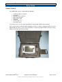
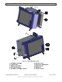
OWL – LONESTAR
TM
SYSTEM USER MANUAL V2.0 - AAN
12/07/10
The LONESTARTM System User Manual
TM
© 2010 OWLSTONE
Ltd
Proprietary and Confidential
The Owlstone logo, OWLSTONE and LONESTAR are trademarks of Owlstone Nanotech, Inc.
Page 1 of 48
OWL – LONESTAR
TM
SYSTEM USER MANUAL V2.0 - AAN
12/07/10
About this Manual
This user manual contains all the information you will need to initially install and run the OWLSTONE
LONESTAR process chemical monitoring system. Additional information and updates are available on the
owlstonenanotech.com website under the support tag.
It is essential that this user manual be read and understood before commencing any
work with the system. Read and understand the various precautionary notes, signs,
and symbols contained inside this manual pertaining to the safe use and operation of
this product before using the device. Using the LONESTAR system in a way that is not
specified in this manual could be harmful to health of the operator and co-workers.
This symbol is used to highlight a section explaining particularly important safety
considerations
Contents
NOTICES .............................................................. 3
SYSTEM OPTIMIZATION ................................. 27
SETUP GUIDE ..................................................... 7
EXPANSION PORTS ........................................ 29
System Contents ................................................ 7
MAINTENANCE ................................................ 30
Installation and Location ................................... 9
EXTERNAL FILTER .......................................... 31
Before starting ..................................................10
Exhaust ..............................................................10
SCRUBBER CARTRIDGE ................................ 35
Exchanging the filter cartridge ....................... 37
THE LONESTAR SYSTEM SOFTWARE GUIDE
............................................................................11
CASEWORK ...................................................... 38
Starting the software ........................................11
SERVICING ....................................................... 39
User interface orientation ................................11
DF sweep data ..................................................13
TROUBLESHOOTING ...................................... 40
Reviewing DF Matrix files ................................18
TECHNICAL SPECIFICATION ......................... 41
Exporting a single DF Matrix ...........................20
Exporting a complete directory ...................21
TECHNOLOGY AT A GLANCE ........................ 42
Configuring and gathering continuous mode
data ....................................................................22
System Status ...................................................24
Carrier Gas ....................................................... 43
Mobility ............................................................. 45
Detection and Identification ............................ 46
File Menu ...........................................................26
Plugins ...............................................................26
TM
© 2010 OWLSTONE
Ltd
Proprietary and Confidential
The Owlstone logo, OWLSTONE and LONESTAR are trademarks of Owlstone Nanotech, Inc.
Page 2 of 48
OWL – LONESTAR
TM
SYSTEM USER MANUAL V2.0 - AAN
12/07/10
Notices
Copyright
©2010 OWLSTONE Ltd. All rights reserved. OWLSTONE Ltd provides this user manual to its
customers to use in the Product operation. This manual is copyright protected and no part of this
publication may be reproduced, transmitted, transcribed, stored in a retrieval system or translated
into any language or computer language, in any form or by any means, without the prior written
permission of OWLSTONE Ltd.
TM
The Owlstone logo, OWLSTONE
and LONESTAR
TM
are trademarks of Owlstone Nanotech, Inc.
Swagelok® is a registered trademark of Swagelok Company.
Microsoft® and Windows® are registered trademarks of the Microsoft Corporation and the
embedded Windows software must be used in accordance with Microsoft’s terms and conditions
(see www.microsoft.com)
Disclaimer
OWLSTONE Ltd makes no representations or warranties, either expressed or implied, with respect
to the contents hereof and specifically disclaims any warranties, merchantability or fitness for any
particular purpose. Furthermore, OWLSTONE Ltd reserves the right to revise this publication and to
make changes from time to time in the contents hereof without obligation of OWLSTONE Ltd to
notify any person of such revision or changes.
Notice of Proper Use of OWLSTONE Ltd Instruments
The supplied system is in compliance with international regulations. If this system is used in a
manner not specified by OWLSTONE Ltd, the protection provided by the system could be impaired
Contacting OWLSTONE
Visit the OWLSTONE website (www.OWLSTONEnanotech.com) for up to date contact details and
service support:
For general inquires please email [email protected]
UK Office:
127 Cambridge Science Park,
Milton Road,
Cambridge
CB4 0GD
Tel: +44 (0)1223 428 200
Fax: +44 (0)1223 428 201
TM
© 2010 OWLSTONE
Ltd
US Office:
OWLSTONE Nanotech Inc
400 Rella Boulevard
Suite 160
Suffern, NY 10901
Tel: +1 845-533-4225
Fax: +1 845-533-4232
Proprietary and Confidential
The Owlstone logo, OWLSTONE and LONESTAR are trademarks of Owlstone Nanotech, Inc.
Page 3 of 48
OWL – LONESTAR
TM
SYSTEM USER MANUAL V2.0 - AAN
12/07/10
Recycling and Disposal
This Product has been designed and manufactured with high quality
materials and components, which can be recycled and reused.
This product is required to comply with the European Union's Waste
Electrical & Electronic Equipment (WEEE) Directive 2002/96/EC so should
not be disposed of in normal waste. In some locations the radioactive
source has additional disposal requirements; please consult OWLSTONE
Ltd for details of our recycling and disposal program for this product.
For users outside the European Union consult local authorities for correct
disposal or contact OWLSTONE Ltd.
Certificate of Conformity
OWLSTONE Ltd performs complete testing and evaluation of its products to ensure full compliance
with applicable domestic and international regulations. When the system is delivered to you, it meets
all relevant electromagnetic compatibility (EMC) and safety standards as described in the declaration
below.
OWLSTONE Ltd declares under its responsibility that the electronic product LONESTAR (Process
Monitoring System) is in conformity with the following standards:
•
EMC Directive
The LONESTAR system complies with the following standards
CR47: 2006 Class A Code of Federal Regulations: pt 15 Subpart B – Radio Frequency
Devices – unintentional radiators
EN61326-1:2006 Electrical equipment for measurement, control and laboratory use – EMC
requirements, Group 1, Class B equipment (emission section only)
En1326-1:2006 Electrical equipment for measurement, control and laboratory use – EMC
requirements, Industrial Location Immunity (immunity section only)
EN61000-3-2:200 Electromagnetic compatibility (EMC) – part 3-2: Limits – Limits for
harmonic current emissions (equipment input current up to and including 16A per phase)
EN61000-3-3:1995 (+A1/A2) Electromagnetic compatibility (EMC) – Part 3-2: Limits –
Limitation of voltage changes, voltage fluctuations and flicker in public low voltage supply
systems for equipment with rated current <= 16A per phase and not subject to conditional
connection
•
Low Voltage Safety Compliance
This device complies with Low Voltage Directive EN 61010-1:2001.
Changes that you make to your system may void compliance with one or more of these
EMC and safety standards. Changes to your system include replacing a part or adding
components, options, or peripherals not specifically authorized and qualified by OWLSTONE
Ltd. To ensure continued compliance with EMC and safety standards, replacement parts
and additional components, options, and peripherals must be ordered from OWLSTONE Ltd
or one of its authorized representatives.
TM
© 2010 OWLSTONE
Ltd
Proprietary and Confidential
The Owlstone logo, OWLSTONE and LONESTAR are trademarks of Owlstone Nanotech, Inc.
Page 4 of 48
OWL – LONESTAR
•
TM
SYSTEM USER MANUAL V2.0 - AAN
12/07/10
FCC Compliance Statement
This equipment has been tested and found to comply with the limits for a Class A digital
device, pursuant to Part 15 of the FCC rules. These limits are designed to provide
reasonable protection against harmful interference when the equipment is operated in a
commercial environment. This equipment generates, uses and can radiate radio frequency
energy and, if not installed and used in accordance with the instruction manual, may cause
harmful interference to radio communications. Operation of this equipment in a residential
area is likely to cause harmful interference, in which case the user will be required to correct
the interference at his or her own expense.
Safety Notice
Caution: Read these operating instructions fully before use and pay particular attention
to sections containing this symbol
Always observe the following safety precautions:
•
•
•
•
•
•
•
•
Only connect to an earthed supply socket. THE MAINS ADAPTOR IS CLASS 1 CONSTRUCTION
AND MUST BE EARTHED (GROUNDED)!
Ensure the mains outlet is easily reached to disconnect the unit
Use only the supplied mains adaptor and leads supplied
The equipment is heavy; use the handle provided to lift and carry the unit
Always disconnect the equipment from the mains supply before moving
This equipment is for use in moderate climates only. NEVER use the equipment in damp or wet
conditions
Avoid excessive heat, humidity, dust & vibration
Do not use where the equipment may be subjected to dripping or splashing liquids
Harmful substances
The LONESTAR system can be used with a wide range of samples some of which could
be toxic or harmful. The LONESTAR system is not a fully sealed unit, therefore for this
reason it is essential that the user conduct a risk assessment for the substances to be
used in the LONESTAR and establish safety protocols to cope with the release of such
materials under the normal operation of the unit. These protocols must include suitable
installation (e.g. in a fume cupboard, provision of extraction, etc.) and operational
procedures to protect the operator.
The LONESTAR system is not designed to be a fully sealed unit. Therefore when used with any toxic
or harmful compound, appropriate precautions such as operation under a fume hood is required.
Check chemical compatibility: Materials in the flow path include PTFE, stainless steel, aluminium,
silicon, graphite, circuit board and Viton®. Ensure test atmospheres are neither corrosive nor reactive
with materials in the flow path and can be safely operated at 60°C. If in doubt please contact an
OWLSTONE representative using the contact details provided.
Note that the relative humidity sensors are for indication only. Typically the humidity sensors are
accurate to +/-5%, but they can be affected by the exact makeup of the process sample and can be
easily altered or damaged by certain chemicals.
TM
© 2010 OWLSTONE
Ltd
Proprietary and Confidential
The Owlstone logo, OWLSTONE and LONESTAR are trademarks of Owlstone Nanotech, Inc.
Page 5 of 48
OWL – LONESTAR
TM
SYSTEM USER MANUAL V2.0 - AAN
12/07/10
Radioactive Material
The LONESTAR system contains a radiation source; please refer to the radiation source
materials safety data sheet for more details on safe handling.
Please consult local regulations about your responsibility in regards to the source. For instance in
England and Wales this will be compliance with “the radioactive substance (testing instruments)
(England and Wales) exemption order 2006” and “the ionising radiation regulations 1999”.
In the US the LONESTAR system is manufactured in compliance with U.S. NRC safety criteria in 10
CFR 32.27 so the purchaser is exempt from any regulatory requirements.
For transport purposes the LONESTAR system complies to UN2911 standards for radioactive
sources, and is provided with an identification certificate.
High humidity and acidic conditions can potentially damage the Nickel 63 source; if used in
this manner or if these conditions could potentially occur please consult an OWLSTONE
service engineer about the use of a secondary external downstream filter to prevent spread
of contaminated material
No person shall intentionally or recklessly misuse or without reasonable excuse interfere with
the radioactive substance contained within the LONESTAR system. The source is enclosed
in a non-user serviceable housing with tamper seals.
TM
© 2010 OWLSTONE
Ltd
Proprietary and Confidential
The Owlstone logo, OWLSTONE and LONESTAR are trademarks of Owlstone Nanotech, Inc.
Page 6 of 48
OWL – LONESTAR
TM
SYSTEM USER MANUAL V2.0 - AAN
12/07/10
Setup Guide
System Contents
The LONESTAR system is shipped with the following:
•
•
•
•
•
•
•
•
LONESTAR process monitor
User guide
Radiation source certificate
Mains power adaptor
Mains power cable
Keyboard
Peli transport case
Accessories pack
If any of these items are missing or damaged then contact OWLSTONE Ltd immediately.
Please retain all items and packaging, including the Peli Case, which is required to return the unit to
OWLSTONE for annual service. No responsibility is accepted by OWLSTONE for damage arising
from the use of non-approved packaging.
Figure 1 - Peli Case
TM
© 2010 OWLSTONE
Ltd
Proprietary and Confidential
The Owlstone logo, OWLSTONE and LONESTAR are trademarks of Owlstone Nanotech, Inc.
Page 7 of 48
OWL – LONESTAR
TM
SYSTEM USER MANUAL V2.0 - AAN
12/07/10
Figure 2 – The LONESTAR system
1. Scrubber cartridge
2. Tracker ball
3. Right click button
4. Left click button
5. Scrubber cartridge release
TM
© 2010 OWLSTONE
Ltd
6. External filter
7. Clean gas supply port
8. Exhaust port
9. USB port
10. Power switch
Proprietary and Confidential
The Owlstone logo, OWLSTONE and LONESTAR are trademarks of Owlstone Nanotech, Inc.
Page 8 of 48
OWL – LONESTAR
TM
SYSTEM USER MANUAL V2.0 - AAN
12/07/10
Installation and Location
Total un-packaged system weighs ~ 7.8kg; please take care in handling to avoid injury.
Before using the system, ensure that all power cables are intact with no damaged
insulation or frays.
•
Ensure that the LONESTAR instrument is placed on a solid, level surface, which is able to
support its weight
•
Only use the OWLSTONE supplied power supply
•
Ensure cabling is routed behind the system, at bench level, posing no risk of tripping. Ensure
all cables are detached from the LONESTAR instrument before attempting to move the unit
•
The LONESTAR instrument gets warm during operation, handle with care and ensure there is
adequate ventilation around the system
•
Do not block ventilation holes
•
Do not place in space that is poorly ventilated or confined. Allow at least 50cm clearance from
walls and free flow of air around the system
•
Do not place near flammable materials
TM
© 2010 OWLSTONE
Ltd
Proprietary and Confidential
The Owlstone logo, OWLSTONE and LONESTAR are trademarks of Owlstone Nanotech, Inc.
Page 9 of 48
OWL – LONESTAR
TM
SYSTEM USER MANUAL V2.0 - AAN
12/07/10
Before starting
During standard operating mode air is drawn through the sample inlet and blended with clean air drawn from
the atmosphere via the scrubber (for further details read sample introduction and clean air guide). The
sample and blend air then exit the LONESTAR system via the exhaust.
During operation always apply the following precautions
The pressure in any gas line connected to the system must not exceed 25psi (1.7
bar)
•
Before using the system, ensure that all power cables are intact with no damaged
insulation or frays
•
Ensure the exhaust end cap is removed before applying flows otherwise the system
may be damaged
•
Take care in removing and attaching Swagelok fittings to ensure fingers are not trapped
or the instrument is not damaged by over tightening
•
The scrubber material should not be exposed to strong oxidising agents. Please read
the MSDS for the hydrocarbon scrubber for materials and chemical compatibility
•
Do not operate or adjust any part of the scrubber unit whilst the unit is powered on, or
connected to any gas lines. If positive pressure is being used ensure that the scrubber
air vent is always OPEN
•
Do not operate without scrubber unit
•
Do not open the LONESTAR instrument – there is a risk of electric shock if covers are
removed
Exhaust
A separate exhaust line should be made ready to connect to the exhaust outlet of the
LONESTAR instrument and the scrubber vent. This line should be checked for chemical
compatibility and it is recommended that it is exhausted to a hydrocarbon trap or to a
fume hood.
TM
© 2010 OWLSTONE
Ltd
Proprietary and Confidential
The Owlstone logo, OWLSTONE and LONESTAR are trademarks of Owlstone Nanotech, Inc.
Page 10 of 48
OWL – LONESTAR
TM
SYSTEM USER MANUAL V2.0 - AAN
12/07/10
The LONESTAR System Software Guide
Starting the software
The software will load automatically when the LONESTAR system has started up. If the software does not
appear on your screen double click on the LONESTAR software icon located on the LONESTAR system
desktop. The LONESTAR software user interface is shown in Figure 3 - LONESTAR system software. The
default behaviour is to always open showing the DF Matrix screen.
Figure 3 - LONESTAR system software
User interface orientation
The LONESTAR system user interface is divided into two sections. Figure 4 shows the Navigation bar. This
part of the user interface is always displayed for each feature of the software being used.
Figure 4 - Navigation bar
The second section of the user interface is shown Figure 5. This shows system information of the currently
selected feature of the LONESTAR system software. Currently this is showing the default feature selection,
DF Matrix.
TM
© 2010 OWLSTONE
Ltd
Proprietary and Confidential
The Owlstone logo, OWLSTONE and LONESTAR are trademarks of Owlstone Nanotech, Inc.
Page 11 of 48
OWL – LONESTAR
TM
SYSTEM USER MANUAL V2.0 - AAN
12/07/10
Figure 5 - System information
Navigation toolbar
The navigation toolbar provides access to the LONESTAR system software features and is divided into four
sections, as shown in Figure 6.
Figure 6 - Navigation tool bar
Menu bar – This provides access to the offline analysis tools and exporting and loading of configuration
files.
Tab selection – The tabs in this area allow you to access the main functionality of the LONESTAR system
software. Left clicking on the required tab will change the display in the system information area below.
On Screen keyboard – If a keyboard is not connected to the LONESTAR instrument click on the
keyboard icon to display the on screen keyboard.
System control – This area displays the volume of gas flowing through the LONESTAR and the system
pressure. The ability to switch between positive and negative mode views can also be seen here. The start
button initiates the run to gather data and the status box above provides and indication of each DF sweep’s
progress. The system alarm status is also displayed here.
TM
© 2010 OWLSTONE
Ltd
Proprietary and Confidential
The Owlstone logo, OWLSTONE and LONESTAR are trademarks of Owlstone Nanotech, Inc.
Page 12 of 48
OWL – LONESTAR
TM
SYSTEM USER MANUAL V2.0 - AAN
12/07/10
DF sweep data
Before DF sweep data can be gathered the LONESTAR system has to be configured. The configuration that
was last used will be stored by the LONESTAR system so all of the following steps will not be required each
and every time a run is started. Different configurations can also be saved and loaded into the software
when required.
A number of key system parameters must be stable before data can be gathered.
Please refer to the application notes provided with your LONESTAR system about these
parameters.
Begin configuring the LONESTAR system by clicking on the Settings tab. The system information area will
be updated with the Settings options screen as shown in Figure 7 - Settings options screen.
Figure 7 - Settings options screen
At this point we are only concerned with the DF Matrix settings area of the screen.
TM
© 2010 OWLSTONE
Ltd
Proprietary and Confidential
The Owlstone logo, OWLSTONE and LONESTAR are trademarks of Owlstone Nanotech, Inc.
Page 13 of 48
OWL – LONESTAR
TM
SYSTEM USER MANUAL V2.0 - AAN
12/07/10
Figure 8 - DF Matrix settings
The DF Matrix settings options provide the ability to configure your run to focus on all or part of the DF
Matrix.
Figure 9 - DF Matrix Settings
TM
© 2010 OWLSTONE
Ltd
Proprietary and Confidential
The Owlstone logo, OWLSTONE and LONESTAR are trademarks of Owlstone Nanotech, Inc.
Page 14 of 48
OWL – LONESTAR
TM
SYSTEM USER MANUAL V2.0 - AAN
12/07/10
Setting the DF Sweep range (Linear) – The range over which the DF sweeps will be gathered can be set
by adjusting the set points for the start and end DF values. To obtain a full DF Matrix set the start point to
0% and the end point to 100%. Once your target analyte has been identified you can adjust these options at
a later date to only gather data between two new points over a smaller range e.g. if your target analyte can
be seen at 60% DF you could gather data between 30% and 80% instead.
Setting the DF Sweep range (Custom) – Rather than gathering DF sweeps linearly, it is possible to
configure the software to gather DF sweeps at custom intervals. Start by clicking on the Custom tab under
the Field Intensity area.
The Custom tab allows Field Intensity values to be entered into the cells.
These values will be used by the LONESTAR system to gather a series
of CV sweeps at those defined values.
To enter values, click inside the next available cell and enter the required
Field Intensity. Repeat this until all the required values have been
entered.
Figure 10 - Custom Field Intensity
Once these values have been entered they will be used when gathering
DF Matrix files. To return to gathering data using the linear configuration
click on the Linear tab button.
Figure 11 - Custom Field Intensity
Setting the Number of Lines – The number of lines selected will affect the resolution of the DF Matrix. A
commonly used rule is to divide the DF range by 2 and add 1, however any number of lines can be chosen.
In Figure 9 the number of lines is set to 51 for a range of 0% to 100%. The number of lines also affects the
time taken to complete a full DF Matrix.
Average CV Sweeps – The number of averages for each DF sweep can be changed for increased
resolution of the peaks. However this will increase the run time for each DF sweep and the overall time
taken to gather 1 DF Matrix.
Min DF Matrix Interval, sec – Setting this value puts a delay between the end of a DF Matrix and the
beginning of the next DF Matrix.
TM
© 2010 OWLSTONE
Ltd
Proprietary and Confidential
The Owlstone logo, OWLSTONE and LONESTAR are trademarks of Owlstone Nanotech, Inc.
Page 15 of 48
OWL – LONESTAR
TM
SYSTEM USER MANUAL V2.0 - AAN
12/07/10
Min CV Sweep Interval, sec – Setting this value puts a delay between each individual CV sweep in the DF
Matrix.
DF Matrix Length, sec – this will update automatically as the above settings are changed. The time shown
represents the total time taken to capture one DF Matrix to the configuration created.
Once the DF Matrix settings have been configured, click on the DF Matrix tab in the navigation bar.
Figure 12 - DF screen
Before the run can be started the system pressure and gas flow must be set by
pressurising the LONESTAR system and adjusting the exhaust restriction until the
desired flow is reached. The optimal pressure and flow settings can be found in the
application notes supplied with your instrument.
Once the pressure and flow have been set and are stable, click on the green Start button to begin gathering
data.
A pop up window will appear into which you can enter the filename of the DF Matrix file, clicking on OK will
begin the run.
The Logging To text box will be updated and display the currently defined filename.
TM
© 2010 OWLSTONE
Ltd
Proprietary and Confidential
The Owlstone logo, OWLSTONE and LONESTAR are trademarks of Owlstone Nanotech, Inc.
Page 16 of 48
OWL – LONESTAR
TM
SYSTEM USER MANUAL V2.0 - AAN
12/07/10
If required a prefix can be entered that will be appended to the original filename. This must be entered into
the Prefix text box on the screen before the DF Matrix file has reached is end value.
If the Cancel button is clicked instead of the OK button the run will still start but the data
will not be saved. To stop the run in this instance click on the red Cancel button.
As the run begins you will begin to see the DF Matrix being constructed in both the positive and negative
mode areas.
Figure 13 - Data collection
The DF Matrix can be rescaled in both positive and negative modes to increase visibility of the peaks. This
is done by moving the Rescale Ion Current bars either side of the DF Matrix.
Below the DF Matrix is a graphical representation of the last captured individual DF sweep. In Figure 13
these are showing the ion current captured at 34% DF. Within the graphical view are 3 cursors: red, green
and blue. These can be dragged onto a peak of interest to monitor changes in the peak size/position whilst
data is being gathered.
Once all of the required DF Matrix files have been captured, click on the red stop button to finish the run.
TM
© 2010 OWLSTONE
Ltd
Proprietary and Confidential
The Owlstone logo, OWLSTONE and LONESTAR are trademarks of Owlstone Nanotech, Inc.
Page 17 of 48
OWL – LONESTAR
TM
SYSTEM USER MANUAL V2.0 - AAN
12/07/10
Reviewing DF Matrix files
DF Matrix files that have been saved can be viewed at any time, even whilst the LONESTAR system is
gathering data. This feature is called Review DF Matrix files and is accessed by clicking on the Plugins
menu item, then selecting Review and finally clicking on DF Matrix file.
Figure 14 – Selecting review DF Matrix file
The Review DF Matrix file window will be displayed.
Figure 15 - Review DF Matrix file
To load a DF Matrix file click on the File menu item and click on Load data. A Windows search box will be
displayed so that you can navigate to the location of the saved files and once selected the DF Matrix will
automatically be displayed.
TM
© 2010 OWLSTONE
Ltd
Proprietary and Confidential
The Owlstone logo, OWLSTONE and LONESTAR are trademarks of Owlstone Nanotech, Inc.
Page 18 of 48
OWL – LONESTAR
TM
SYSTEM USER MANUAL V2.0 - AAN
12/07/10
Figure 16 - DF Matrix review
The DF Matrix for positive and negative mode responses is displayed at the top of the screen. The ion
current at a single DF sweep can be seen in the graphical view below the positive and negative mode DF
Matrix images. The ion current can be rescaled so that more detail can be seen in the DF Matrix. This is
done by adjusting the Rescale slide bars to the right of the DF Matrix.
Figure 17 - Rescaled DF Matrix
TM
© 2010 OWLSTONE
Ltd
Proprietary and Confidential
The Owlstone logo, OWLSTONE and LONESTAR are trademarks of Owlstone Nanotech, Inc.
Page 19 of 48
OWL – LONESTAR
TM
SYSTEM USER MANUAL V2.0 - AAN
12/07/10
The ion current at a single DF sweep can be seen in the graphical view below the positive and negative
mode DF Matrix images.
Figure 18 - DF Sweep graph view
The graph displays the data at a single DF sweep from the DF Matrix. This position is set by moving the
cursor within the DF Matrix to the desired point. Alternatively the required DF can be manually entered into
DF cursor boxes located underneath each of the DF Matrices. The graphic view will be automatically
updated as the DF cursor position is changed.
The peak values can be obtained by moving one of the three cursors within the graph view onto a peak of
interest. This gives the ability to monitor peak size and peak position over time.
To see a sequence of saved DF Matrix files click on the Next button located at the bottom of the screen.
The next DF Matrix file will be automatically loaded from the same directory. Clicking on the previous button
will load the DF Matrix file captured before the last one viewed.
The DF Matrix review feature also provides the ability to export the DF Matrix files into ASCII file format so
that the data can be viewed using spreadsheet or notepad software
Exporting a single DF Matrix
A single DF Matrix file can be exported when it is displayed in the Review DF Matrix file software. Begin by
loading or displaying the required DF Matrix using the DF Matrix review feature.
Next select the File menu item and choose Export file from the list.
Figure 19 - Exporting a File
TM
© 2010 OWLSTONE
Ltd
Proprietary and Confidential
The Owlstone logo, OWLSTONE and LONESTAR are trademarks of Owlstone Nanotech, Inc.
Page 20 of 48
OWL – LONESTAR
TM
SYSTEM USER MANUAL V2.0 - AAN
12/07/10
A window will be displayed so that the location of the exported file can be set. Navigate to the required
location and click on OK.
Figure 20 - Naming a file
The exported file will be created in the specified location. This can be repeated multiple times for single DF
Matrix files.
Exporting a complete directory
If multiple DF Matrix files need to be exported then this can be done using the Folder Export feature.
Begin by opening the DF Matrix review tool. Next select the File menu item and choose Export file from the
list.
Figure 21 - Export Folder
TM
© 2010 OWLSTONE
Ltd
Proprietary and Confidential
The Owlstone logo, OWLSTONE and LONESTAR are trademarks of Owlstone Nanotech, Inc.
Page 21 of 48
OWL – LONESTAR
TM
SYSTEM USER MANUAL V2.0 - AAN
12/07/10
A folder export can be carried out without loading a DF Matrix into the DF Matrix review
tool. It is possible to navigate to the directory containing the DF Matrices and simply
export the entire directory without viewing them first.
Configuring and gathering continuous mode data
Continuous DF data differs from DF Matrix data in that it is gathered at one specific DF. This allows
continuous monitoring of a known analyte at a constant DF, the advantage of this is that it provides a very
quick visual indication that the analyte has changed in some way.
Before Continuous DF data can be gathered the LONESTAR system has to be configured. The
configuration that was last used will be stored by the LONESTAR system so all of the following steps will not
be required each and every time a run is started. Different configurations can also be saved and loaded into
the software when required.
A number of key system parameters must be stable before data can be gathered.
Please refer to the application notes provided with your LONESTAR system about these
parameters.
Begin configuring the LONESTAR system by clicking on the Settings tab. The system information area will
be updated with the Settings options screen as shown in Figure 22.
Figure 22 - System Settings
TM
© 2010 OWLSTONE
Ltd
Proprietary and Confidential
The Owlstone logo, OWLSTONE and LONESTAR are trademarks of Owlstone Nanotech, Inc.
Page 22 of 48
OWL – LONESTAR
TM
SYSTEM USER MANUAL V2.0 - AAN
12/07/10
Once the Continuous DF settings have been configured, click on the Continuous tab in the navigation bar.
Figure 23 - Continuous Tab
Before the run can be started the system pressure and gas flow must be set by
pressurizing the LONESTAR system and adjusting the exhaust restriction until the
desired flow is reached. The optimal pressure and flow settings can be found in the
application notes supplied with your instrument.
Figure 24 - Continuous Mode
The required field intensity can be set by dragging the slide bar within the Field Intensity % box to the
required value. If required the field intensity can also be changed whilst data is being gathered.
Once the pressure and flow have been set and are stable, click on the green Start button to begin gathering
data.
A pop up window will appear into which you can enter a filename for the data, clicking on OK will begin the
run.
The Logging To text box will be updated and display the currently defined filename.
TM
© 2010 OWLSTONE
Ltd
Proprietary and Confidential
The Owlstone logo, OWLSTONE and LONESTAR are trademarks of Owlstone Nanotech, Inc.
Page 23 of 48
OWL – LONESTAR
TM
SYSTEM USER MANUAL V2.0 - AAN
12/07/10
If the Cancel button is clicked instead of the OK button the run will still start but the data
will not be saved. To stop the run in this instance click on the red Cancel button.
System Status
The system status screen displays active detailed information about the LONESTAR system’s key system
variables. Monitoring and knowing these variables is vital to gathering stable and repeatable data.
To display the System Status screen click on the Status tab.
Figure 25 - System Status
The left hand side of the screen shows simple spark lines with the last recorded value.
Sensor conditions
The sensor conditions are critical to gathering data and need to be fully understood. Each of them will have
an impact on the quality of the data and should be regularly checked.
•
Flow Rate – Displays the gas flow through the LONESTAR system in litres/min. A stable
flow must be achieved before data should be gathered. If the flow is unstable or does not
reach the required set point then refer to the troubleshooting guide in the application notes
•
Pressure – Displays the pressure within the LONESTAR system in bar. A stable pressure
must be achieved before data should be gathered. If the pressure is unstable or does not
reach the required set point then refer to the troubleshooting guide in the application notes
•
Humidity – Shows the relative humidity of the gas flowing through the LONESTAR system
•
Temperature – This temperature must have stabilized or be near the maximum reading that
can be achieved. This parameter can also be graphed within this screen to show the trend
of the data, i.e. has it stabilized or is it still climbing?
•
Field Intensity – Updates as the DF Matrix is constructed
TM
© 2010 OWLSTONE
Ltd
Proprietary and Confidential
The Owlstone logo, OWLSTONE and LONESTAR are trademarks of Owlstone Nanotech, Inc.
Page 24 of 48
OWL – LONESTAR
TM
SYSTEM USER MANUAL V2.0 - AAN
12/07/10
System Temperatures
The next set of variables is the System temperatures. These are still important to the operation of the
LONESTAR system and should be checked to ensure that they have reached the maximum stable operating
temperature:
•
Sensor Head – This is the current operating temperature of the sensor head. This must have
reached or be near its maximum stable temperature. By default the sensor head should reach 60°C
± 2°. If the temperature is not reaching this range then consult the troubleshooting guide provided in
the hardware manual supplied with the LONESTAR system
•
Filter – The inlet filter temperature must be operating near or at its maximum temperature. The set
point is 100°C ± 2°. If the temperature is not reaching this range then consult the troubleshooting
guide in the hardware manual supplied with the LONESTAR system
•
Motherboard – An indication of the operating temperature of the LONESTAR motherboard
•
Ambient – The ambient temperature within the LONESTAR body
All of these parameters can be plotted using the dual axis graph feature displayed on the right hand side of
the screen.
Figure 26 - Dual Graph
To display a parameter on the graph click on the drop down menu and select the one required. The scales
will be automatically adjusted.
TM
© 2010 OWLSTONE
Ltd
Proprietary and Confidential
The Owlstone logo, OWLSTONE and LONESTAR are trademarks of Owlstone Nanotech, Inc.
Page 25 of 48
OWL – LONESTAR
TM
SYSTEM USER MANUAL V2.0 - AAN
12/07/10
File Menu
The File menu item provides access to the Configuration menu. The configuration feature allows you to
create a system configuration which can then be saved a reloaded multiple times. This saves time when
setting up the system and ensures that a consistent system set up is applied each time data is collected.
Three configuration options are available.
•
New Configuration
•
Load Configuration
•
Save Configuration
To access these menu items click on File in the toolbar and then choose the required option.
Figure 27 - Configurations
Configuration Options
•
New Configuration – Clicking on this option will clear the existing configuration being used on the
LONESTAR system and reload the system default configuration file. The configuration identifier in
the toolbar will be updated to reflect your selected configuration.
•
Load Configuration – This option allows you to reload any saved configuration. When selected, a
navigation window will be displayed to locate the required file. Once located either double clicking
on the configuration file or selecting it and then clicking OK will load it into the LONESTAR system
software. The configuration identifier in the toolbar will be updated to reflect your selected
configuration.
•
Save Configuration – Once the LONESTAR system software has been optimized to your
requirements you can save the configuration directly from the LONESTAR system software by
clicking this option. All of your LONESTAR system settings will be exported into a configuration file
which can be saved in the chosen
Plugins
The Plugins menu item provides access to the Matrix review software and Easyspec. To access these
menu items click on Plugins in the toolbar and then choose the required option.
Figure 28 - Plugins
TM
© 2010 OWLSTONE
Ltd
Proprietary and Confidential
The Owlstone logo, OWLSTONE and LONESTAR are trademarks of Owlstone Nanotech, Inc.
Page 26 of 48
OWL – LONESTAR
TM
SYSTEM USER MANUAL V2.0 - AAN
12/07/10
System Optimization
Due to the versatility and dynamics of the LONESTAR system there may be some instances when the
spectral output can become crowded and difficult to read. This is a result of many variables but various
adjustments can be made to optimize the spectral output.
No Peak – If a system produces no peak at all a number of issues could be the cause and can show itself in
a number of ways which are listed below:
•
When running the system at 0 % DF, if there is simply a noise line at or around 0 au in height with no
sign of a peak this indicates there are no ions passing through the chip to the detector. To rectify,
first, check the main pump or regulator is on and flow is present in the system. Second, check
whether the mode of operation requires some fixtures to be removed or replaced. In an extreme
situation the particulate filter could be blocked and may need replacing
•
Sometimes when running at 0 % DF there is a peak but when running at elevated DF values the
peaks are no longer observable. This is due to ion attenuation and is a perfectly normal
phenomenon related to the size of the sample analyte passing through the device and its
concentration. Large molecular ions will give a response over the full range of DF values whereas
small ions will only have a short range. To overcome these problems try focussing the DF value
from 25 to 45 % in order to observe the smaller ions.
•
When running the system at any DF value, if the response is a flat line at or around 10 au then an
OWLSTONE technician should be contacted. This may indicate that the FAIMS chip is damaged –
although this is extremely rare.
System saturation – this occurs when there too many ions striking the detector plate, and as a result the
peak(s) may have the top ‘chopped off’ or clipped, this is caused by the ion count overwhelming the
detecting electronics. Another example of saturation can be observed from peak height and width; if either
of these are excessively large then saturation has occurred.
•
•
Clipping – When running the system at 0 % DF with no sample flow, if the only peak is clipped then
the flow rate is too high. The needle valve on the LONESTAR exhaust controls the flow rate and
this should be adjusted until the correct flow is displayed in the software. The pressure within the
LONESTAR will also change as the flow is decreased, check the pressure reading and adjust to
the required set point.
Clipping – When running the system at 0 % DF with the sample flow on, if the only peak present is
clipped this may indicate a very high concentration of sample vapour entering the system. Check
the sample and reduce to the lowest setting (lowest flow) in steps until the signal no longer clips.
Excessive peak size – When operating the system at DF values of 30 % and above, if any peak
within the positive section of the compensation voltage sweep is wider than 2V at the peak base
and over 7 au in height this could be obscuring extra information. Either reduce the flow rate as
covered in the Clipping instructions above or reduce the sample concentration. This can be done
by preparing the sample at a lower concentration or splitting off some of the analyte before the
LONESTAR sample inlet. Turn down the sample wheel, in steps until this peak has reduced
sufficiently.
TM
© 2010 OWLSTONE
Ltd
Proprietary and Confidential
The Owlstone logo, OWLSTONE and LONESTAR are trademarks of Owlstone Nanotech, Inc.
Page 27 of 48
OWL – LONESTAR
TM
SYSTEM USER MANUAL V2.0 - AAN
12/07/10
Peak Mirroring – In extreme circumstances the peak in one polarity can be large enough to impact on the
opposite polarity spectrum. This is due to high ion concentrations of one polarity interfering with the
detection electronics. Mirroring is only detrimental if there is information in both detection polarities with one
polarity overwhelming the other.
•
Mirroring – High ion counts can be limited by changing the sample flow through the sample wheel,
as mentioned in the clipping section, and by changing the main pump voltage or flow.
Minimal Peak Movement – All peaks within the spectral window should move left or right as the DF values
are increased. Very few ions will remain on a straight line in the spectrum, such an observation may indicate
a problem (charged particulates may be an exception to this rule).
If a peak that does not move left or right is genuine then its height and width will change with increasing DF
value. This can be monitored using the offline software where the integrated ion current should show a
general downward trend. If, however, this result is constant it may indicate the RF generation stage has
broken and needs repair.
TM
© 2010 OWLSTONE
Ltd
Proprietary and Confidential
The Owlstone logo, OWLSTONE and LONESTAR are trademarks of Owlstone Nanotech, Inc.
Page 28 of 48
OWL – LONESTAR
TM
SYSTEM USER MANUAL V2.0 - AAN
12/07/10
Expansion Ports
The LONESTAR system possesses several interface ports:
Front and rear USB – For use with Memory Sticks, Keyboards and Mice only.
GPIO (General Purpose Input/Output) port – System integration port allowing additional sensor inputs
2
and outputs via industry standard I C interface.
GPIO pin out:
Pin No:
1
2
3
4
5
6
7
8
9
Name:
DIO 0
DIO 1
GND
+5V
AO
DIO 2
DIO 3
AI 1
AI 2
Notes:
Digital Input Output (0-5V)
Digital Input Output (0-5V)
GND
Max draw 200mA
Analogue Output (0-5V)
Digital Input/Output (0-5V)
Digital Input/Output (0-5V)
Analogue Input (0-10V)
Analogue Input (0-10V), normally not connected
Contact OWLSTONE for further details on GPIO system integration
RJ45 Network connector – Networking is available on the LONESTAR system via standard Microsoft
Windows protocols to enable file transfer and update
TM
© 2010 OWLSTONE
Ltd
Proprietary and Confidential
The Owlstone logo, OWLSTONE and LONESTAR are trademarks of Owlstone Nanotech, Inc.
Page 29 of 48
OWL – LONESTAR
TM
SYSTEM USER MANUAL V2.0 - AAN
12/07/10
Maintenance
Basic checks
•
•
•
Regularly check that the main LED indicator glows when power is applied. The unit must NOT be
operated if the indicator fails and must be returned for servicing. The fuse in the mains cable plug
must only be replaced with a 5A BS1362 type (UK only)
If a replacement fuse fails immediately, contact your local service agent. DO NOT replace with a
higher rated fuse
The mains adaptors are designed to comply with BS EN 60950-1 and can be flash tested.
Do not attempt any maintenance whilst the unit is powered on, or connected to any gas
lines.
TM
© 2010 OWLSTONE
Ltd
Proprietary and Confidential
The Owlstone logo, OWLSTONE and LONESTAR are trademarks of Owlstone Nanotech, Inc.
Page 30 of 48
OWL – LONESTAR
TM
SYSTEM USER MANUAL V2.0 - AAN
12/07/10
External Filter
Every precaution should be taken to keep the filter parts clean. It is recommended that
gloves are worn when handling the filter assembly. Any contact with fingers can leave
greasy deposits which will cause contamination.
Figure 29 - External filter assembly
Figure 30 - Filter components
1. Outlet body
2. Locking ring
3. Inlet body
4. PTFE gasket
TM
© 2010 OWLSTONE
Ltd
5. Stainless steel screen
6. PTFE filter membrane
7. Stainless steel screen
8. PTFE gasket
Proprietary and Confidential
The Owlstone logo, OWLSTONE and LONESTAR are trademarks of Owlstone Nanotech, Inc.
Page 31 of 48
OWL – LONESTAR
TM
SYSTEM USER MANUAL V2.0 - AAN
12/07/10
Before removing the external filter assembly the following two steps must be followed.
1. Stop gathering data by clicking on the Stop button. This can be found on the main navigation bar in
the LONESTAR system software
2. Next, switch the Filter Heater off and allow the filter body to cool. The filter heater is turned off by
clicking on the Filter Heater button which can be found on the Settings tab. Once this is done the
temperature can be monitored on the Status screen
Figure 31 - Filter Heater option
The filter body will be extremely hot and should not be handled until it has cooled.
3. Whilst the filter body is cooling switch the LONESTAR system gas flow into Purge mode. This is
done by clicking the Gas Purge button which can be found on the Settings tab. Doing this will
redirect the gas flow so that it flows out of the sample inlet, preventing any particulates being able to
enter the LONESTAR system whilst the filter has been removed
4. When the filter has cooled remove the filter assembly. Using a 5/8 inch spanner on the outlet body
(part 1, Figure 29) turn the filter anticlockwise until it can be removed from the inlet heater
5. Next undo the Locking ring (part 2, Figure 29). This can be undone by hand but occasionally it may
be necessary to fit an adjustable spanner to the Locking Ring and a 5/8 inch spanner to the outlet
body (part 1, Figure 29) and then undo the two parts
It is advisable to separate the two parts over a bench or clean tray as some inner parts
may fall out as the pieces are separated.
6. Once separated the filter components will be visible as seen in Figure 32.
Filter
Components
TM
© 2010 OWLSTONE
Ltd
Figure 32 - Filter components
Proprietary and Confidential
The Owlstone logo, OWLSTONE and LONESTAR are trademarks of Owlstone Nanotech, Inc.
Page 32 of 48
OWL – LONESTAR
TM
SYSTEM USER MANUAL V2.0 - AAN
12/07/10
7. Next take the outlet body (part 1, Figure 29) and gently tap it down onto a bench or hard surface to
encourage the filter components to drop out. As they are compressed into place sometimes they
can be difficult to remove so try to avoid damaging any parts whilst doing this.
8. Once the filter components have been removed discard the PTFE membrane (part 5, Figure 30)
9. Begin to reassemble the filter components into the outlet body in the following order:
Fit one of the PTFE gaskets into the outlet body
Fit one of the stainless steel screens onto the
PTFE gasket
Place the new PTFE membrane filter onto the
stainless steel screen
Fit the second stainless steel screen over the
PTFE membrane filter
Finally place the second PTFE gasket onto the
stainless steel screen
TM
© 2010 OWLSTONE
Ltd
Proprietary and Confidential
The Owlstone logo, OWLSTONE and LONESTAR are trademarks of Owlstone Nanotech, Inc.
Page 33 of 48
OWL – LONESTAR
TM
SYSTEM USER MANUAL V2.0 - AAN
12/07/10
10. Before fitting the filter assembly back together check that the Locking Ring gasket is fitted into the
Inlet body as shown in Figure 33.
Locking ring gasket
Figure 33 - Locking ring gasket
11. The next step is to fit the filter bodies back together and tighten up the locking ring.
Figure 34 - Final assembly
12. Remove the old PTFE tape from the fittings and replace it with new PTFE tape. Ensure that there
are no threads of PTFE tape within the flow path.
13. Finally the external filter can be fitted back onto the LONESTAR system. Before fitting the filter
remove any strands of PTFE sealing tape from the LONESTAR system inlet port threads. Check
that the outlet body thread has sufficient PTFE sealant tape around the thread and then screw the
filter body in until it is tight.
TM
© 2010 OWLSTONE
Ltd
Proprietary and Confidential
The Owlstone logo, OWLSTONE and LONESTAR are trademarks of Owlstone Nanotech, Inc.
Page 34 of 48
OWL – LONESTAR
TM
SYSTEM USER MANUAL V2.0 - AAN
12/07/10
Scrubber Cartridge
Before removing the scrubber cylinder, ensure that the gas supply to the LONESTAR
system has been switched off.
Before handling the Hydrocarbon refill please consult the Carbon Refill Material Safety
Data Sheet (MSDS) supplied.
1. Begin by removing the scrubber from the LONESTAR instrument by pressing down on the scrubber
cartridge release
Figure 35 - Scrubber removal
2. Next unscrew the scrubber cap in an anticlockwise direction and remove it from the scrubber body.
TM
© 2010 OWLSTONE
Ltd
Proprietary and Confidential
The Owlstone logo, OWLSTONE and LONESTAR are trademarks of Owlstone Nanotech, Inc.
Page 35 of 48
OWL – LONESTAR
TM
SYSTEM USER MANUAL V2.0 - AAN
12/07/10
Scrubber cap
Scrubber body
Figure 36 - Scrubber cartridge
3. Pour the hydrocarbon media in the lower section of the scrubber into a container, taking the
necessary precautions detailed in the MSDS.
4. Refill the lower section of the scrubber with the new hydrocarbon media, up to the internal fill line
(approximately 3 cm from the top edge of the scrubber body).
5. Ensure that the hydrocarbon particulates have settled by gently tapping the scrubber body. Top up
the hydrocarbon media if the level has dropped.
6. Finally screw the scrubber cap back onto the scrubber body until tight. Ensure that the o-ring seal
between the cap and body is still intact after tightening. Any damage to this o-ring could cause a
leak to occur. If the o-ring is damaged it must be replaced.
TM
© 2010 OWLSTONE
Ltd
Proprietary and Confidential
The Owlstone logo, OWLSTONE and LONESTAR are trademarks of Owlstone Nanotech, Inc.
Page 36 of 48
OWL – LONESTAR
TM
SYSTEM USER MANUAL V2.0 - AAN
12/07/10
Figure 37 - O-ring seal
Before disposing of any used hydrocarbon media please read the Hydrocarbon MSDS
supplied with the LONESTAR system.
Exchanging the filter cartridge
1. Begin by removing the scrubber from the LONESTAR instrument by pressing down on the scrubber
cartridge release (Figure 35)
2. Next unscrew the Scrubber cap in an anticlockwise direction and remove it from the scrubber body
3. Finally unscrew the filter cartridge assembly by holding onto the cylinder cap and turning the filter
assembly in an anticlockwise direction.
Figure 38 - Filter Assembly
TM
© 2010 OWLSTONE
Ltd
Proprietary and Confidential
The Owlstone logo, OWLSTONE and LONESTAR are trademarks of Owlstone Nanotech, Inc.
Page 37 of 48
OWL – LONESTAR
TM
SYSTEM USER MANUAL V2.0 - AAN
12/07/10
4. Screw the new filter cartridge assembly into the scrubber cap taking care not to over tighten the
threads
5. Finally screw the scrubber cap back onto the scrubber body until tight. Ensure that the o-ring seal
between the cap and body is still intact after tightening. Any damage to this o-ring could cause a
leak to occur. If the o-ring is damaged it must be replaced.
Figure 39 - O-ring seal
Casework
Wipe the casework with a damp cloth only. Do not wet or allow moisture to penetrate the unit. Do not use
solvents
TM
© 2010 OWLSTONE
Ltd
Proprietary and Confidential
The Owlstone logo, OWLSTONE and LONESTAR are trademarks of Owlstone Nanotech, Inc.
Page 38 of 48
OWL – LONESTAR
TM
SYSTEM USER MANUAL V2.0 - AAN
12/07/10
Servicing
It is highly recommended that the LONESTAR system undergoes an annual service, as well as retesting and
calibrating to factory acceptance standards. At the same time the unit will undergo a wipe test to ensure no
radioactive contamination has escaped the housing. In some regions this is a regulatory requirement and a
Certificate of Conformance will be supplied at each service.
PLEASE NOTE: Opening the electrical case of the product voids the warranty.
To arrange a service use the OWLSTONE website to obtain an RMA (Return Merchandise Authorization)
number and transport address. Alternatively contact OWLSTONE on the service number +44 (0)845 838
9866 or at supportowlstone.co.uk
Do not send a LONESTAR system back to OWLSTONE without first obtaining an RMA
and filling in the decontamination certificate provided with the RMA. For legal and health
and safety reasons OWLSTONE cannot accept any LONESTAR system without the
correct paperwork.
The LONESTAR system will only be accepted if returned in its original Peli case.
TM
© 2010 OWLSTONE
Ltd
Proprietary and Confidential
The Owlstone logo, OWLSTONE and LONESTAR are trademarks of Owlstone Nanotech, Inc.
Page 39 of 48
OWL – LONESTAR
TM
SYSTEM USER MANUAL V2.0 - AAN
12/07/10
Troubleshooting
Symptom
Possible cause/remedy
Not reaching set flow rate
o
Filter clogged – Change filter
o
Scrubber restriction – Check scrubber
o
Exhaust restriction – Check exhaust
o
Flow path restriction – Contact service engineer
o
Flow sensor malfunction – Contact service engineer
o
Check mains and fuse
o
Check hard on/off switch at back of unit
o
Other – Contact service engineer
Sensor or filter temperature
does not reach set-point
o
Contact service engineer
Humidity not reaching
desired level
o
Faulty humidity sensor – contact service engineer
o
Incorrect scrubber/scrubber consumed – replace/refill scrubber
o
External air supply is wet
o
Dirty sampling interface, pipe-work – Clean pipework
o
Scrubber may need its contents changing
o
Leave system running with clean dry air and all heaters on for 1 day
o
Particulate filter is contaminated and needs replacing.
USB accessory not
detected
o
Faulty USB, software did not detect device – try second USB port
Software freezes
o
Reboot by pressing front on/off button twice
NI error message
o
Reboot, if problem persists please contact service engineer with error
message code
No background ion peak
o
Check scrubber is properly mounted
o
Check for a leak in the flow path
System does not boot
Contamination
For questions and troubleshooting advice please contact us at [email protected], please have the
LONESTAR system serial number and current software version available. If an internet connection is
available it is also possible to enable remote access to the LONESTAR system to assist the troubleshooting
process.
TM
© 2010 OWLSTONE
Ltd
Proprietary and Confidential
The Owlstone logo, OWLSTONE and LONESTAR are trademarks of Owlstone Nanotech, Inc.
Page 40 of 48
OWL – LONESTAR
TM
SYSTEM USER MANUAL V2.0 - AAN
12/07/10
Technical Specification
Operating Condition
Input Voltage (to main power
adaptor)
Input Current (to main power
adaptor)
Description
115V to 250V, 50-60Hz AC
1A (max) at 115V
0.5A (max) at 240V
Storage Temperature range
-30C - +60C (unit off)
Operating Temperature range
5C – 40C
Operating Humidity range
5% - 90%RH
Weight
7.8kg
Front USB
Back USB
GPIO port
Connectors
Network port
Power connector
Mains adaptor qualification
TM
© 2010 OWLSTONE
Ltd
The mains adaptor is for operation at
installation category II (transient voltages)
and pollution degree ll in accordance with
IEC 664 at altitudes up to 2000 metres.
Proprietary and Confidential
The Owlstone logo, OWLSTONE and LONESTAR are trademarks of Owlstone Nanotech, Inc.
Page 41 of 48
OWL – LONESTAR
TM
SYSTEM USER MANUAL V2.0 - AAN
12/07/10
Technology at a Glance
Field asymmetric ion mobility spectrometry (FAIMS), also known as differential mobility spectrometry (DMS),
is a gas detection technology that separates and identifies chemical ions based on their mobility under a
varying electric field at atmospheric pressure. Figure 40 is a schematic illustrating the operating principles of
FAIMS.
RF waveform
0V
Pk to Pk V
Ionisation source
+
+ +
- -
-6
+
+
Electrode channel
+
+
++
- + +- +
Ion count
C 0
V
+
6
Detector
Sample
Preparation and introduction
Ionization
Ion separation based on mobility
Detection
Exhaust
Air /carrier gas flow direction
Figure 40 FAIMS schematic. The sample in the vapor phase is introduced via a carrier gas to the
ionisation region, where the components are ionised via a charge transfer process or by direct
ionisation dependent on the ionisation source used. It is important to note that both positive and
negative ions are formed. The ion cloud enters the electrode channel, where an RF waveform is
applied to create a varying electric field under which the ions follow different trajectories
dependent on the ions’ intrinsic mobility parameter. A DC voltage (compensation voltage) is
swept across the electrode channel shifting the trajectories so different ions reach the detector,
Sample
preparationdetects
and introduction
which simultaneously
both positive and negative ions. The number of ions detected is
proportional to the concentration of the chemical in the sample.
FAIMS can be used to detect volatiles in aqueous, solid and gaseous matrices and can consequently be
used for a wide variety of applications. The user requirements and sample matrix for each application define
the sample preparation and introduction steps required. There are a wide variety of sample preparation,
extraction and processing techniques each with their own advantages and disadvantages. It is not the scope
of this overview to list them all, only to highlight that the success of the chosen application will depend
heavily on this critical step, which can only be defined by the user requirements.
There are two mechanisms of introducing the sample into the FAIMS unit: discrete sampling and continuous
sampling. With discrete sampling, a defined volume of the sample is collected by weighing or by volumetric
measurement via a syringe, or passed through an adsorbent for pre-concentration, before it is introduced
into the FAIMS unit. An example of this would be attaching a sample container to the instrument containing a
fixed volume of sample. Where a carrier gas (usually clean dry air) is used to transfer the sample to the
ionization region. Continuous sampling is where the resultant gaseous sample is continuously purged into
the FAIMS unit and either diluted by or acts as the carrier gas. For example, continuously drawing air from
the top of a process vat.
The one key requirement for all the sample preparation and introduction techniques is the ability to
reproducibly generate and introduce a headspace (vapor) concentration of the target analytes that
exceeds the lower limits of detection of the FAIMS device.
TM
© 2010 OWLSTONE
Ltd
Proprietary and Confidential
The Owlstone logo, OWLSTONE and LONESTAR are trademarks of Owlstone Nanotech, Inc.
Page 42 of 48
OWL – LONESTAR
TM
SYSTEM USER MANUAL V2.0 - AAN
12/07/10
Carrier Gas
The requirement for a flow of air through the system is twofold:
Firstly to drive the ions through the electrode channel to the
detector plate and secondly, to initiate the ionization process
necessary for detection.
As exhibited in Error! Reference source not found., the
transmission factor (proportion of ions that make it to the detector)
increases with increasing flow. The higher the transmission factor,
the higher the sensitivity. Higher flow also results in a larger full
width half maximum (FWHM) of the peaks, however, decreasing
the resolution of FAIMS unit (see Figure 42).
Figure 41 Flow rate vs. ion
As the air carrier gas determines the baseline reading of the transmission factor
instrument. Therefore, for optimal operation it is desirable for the
carrier to be free of all impurities (<0.1 ppm methane) and the
humidity to be kept constant. It can be supplied either from a pump or
compressor, allowing for negative and positive pressure operating
modes.
Ionization Source
There are three main vapor phase ion sources in use for atmospheric
pressure ionization: radioactive nickel-63 (Ni-63), corona discharge
Figure 42 FWHM of ion species at
(CD) and ultra-violet radiation (UV). A comparison of ionization
set CV
sources is presented in Table 1.
Ni-63 undergoes beta decay, generating energetic electrons, where as CD ionization strips electrons from
the surface of a metallic structure under the influence of a strong electric field. The electrons generated
interact with the carrier gas (air) to form stable intermediate ions called reactive ion peak (RIP) with positive
and negative charges. These RIP ions then transfer their charge to neutral molecules through collisions thus
both Ni-63 and CD are known as indirect ionization methods.
Ionisation Source
Mechanism
Chemical Selectivity
Ni (beta emitter) creates a positive / negative
RIP
Charge transfer
Proton / electron affinity
UV (Photons)
Direct ionisation
First ionisation potential
Corona discharge (plasma) creates a positive /
negative RIP
Charge transfer
Proton / electron affinity
63
Table 1 FAIMS ionisation source comparison
For the positive ion formation:
N2 + e- → N2+ + e- (primary) + e- (secondary)
N2+ + 2N2 → N4+ + N2
N4+ + H2O → 2N2 + H2O+
H2O+ + H2O → H3O+ + OH
H3O+ + H2O + N2 ↔ H+(H2O)2 + N2
+
H (H2O)2 + H2O + N2 ↔ H+(H2O)3 + N2
For the negative ion formation:
O2 + e- → O2B + H2O + O2- ↔ O2-(H2O) + B
B + H2O + O2-(H2O) ↔ O2-(H2O)2 + B
TM
© 2010 OWLSTONE
Ltd
Proprietary and Confidential
The Owlstone logo, OWLSTONE and LONESTAR are trademarks of Owlstone Nanotech, Inc.
Page 43 of 48
OWL – LONESTAR
TM
SYSTEM USER MANUAL V2.0 - AAN
12/07/10
The water based clusters (hydronium ions) in the positive mode (blue) and hydrated oxygen ions in the
negative mode (red), are stable ions which form the RIPs. When an analyte (M) enters the RIP ion cloud, it
can replace one or (dependent on the analyte) two water molecules to form a monomer ion or dimer ion
respectively, reducing the number of ions present in the RIP.
Dimer
Monomer
+
+
+
H (H2O)3 + M + N2 ↔ MH (H2O)2 + N2 + H2O ↔ M2H (H2O)1 + N2 + H2O
Dimer ion formation is dependent on the analyte’s affinity to charge and its concentration. This is illustrated
in Figure 43 using dimethyl methylphsphonate (DMMP). In plot A it shows that the RIP decreases with an
increase in DMMP concentration as more of the charge is transferred over to the DMMP. In addition the
monomer ion decreases as dimer formation becomes more favourable at the higher concentrations. This is
shown more clearly in plot B, which plots the peak ion current of both the monomer and dimer at different
concentration levels.
Dimer
Monomer
RIP
Figure 43 DMMP Monomer and dimer formation at different concentrations
Under the action of the indirect ionization process is the manner in which ions are formed is exactly the
same, however, the likelihood of ionization is governed by its affinity towards proton and electrons (Table 2
and Table 3 respectivley).
In complex mixtures where more than one chemical is present, competition for the available charge
occurs resulting in preferential ionization of the compounds within the sample. Thus the chemicals
with high proton or electron affinities will ionize more readily than those with a low proton or
electron affinity. Therefore the concentration of water within the ionization region will have a direct
effect on certain analytes whose proton / electron affinities are lower.
Chemical Family
Example
Proton affinity
Aromatic amines
Pyridine
930 kJ/mole
Amines
Methly amine
899 kJ/mole
Phosphorous
Compounds
Sulfoxides
TEP
891 kJ/mole
DMS
884 kJ/mole
Ketones
2- pentanone
832 kJ/mole
Esters
Methly Acetate
822 kJ/mole
Alkenes
1-Hexene
805 kJ/mole
Alcohols
Butanol
789 kJ/mole
Aromatics
Benzene
750 kJ/mole
Water
691 kJ/mole
Alkanes
Methane
544 kJ/mole
Table 2 Overview of the proton affinity of different chemical families
TM
© 2010 OWLSTONE
Ltd
Proprietary and Confidential
The Owlstone logo, OWLSTONE and LONESTAR are trademarks of Owlstone Nanotech, Inc.
Page 44 of 48
OWL – LONESTAR
TM
SYSTEM USER MANUAL V2.0 - AAN
Chemical Family
Nitrogen Dioxide
Chlorine
12/07/10
Electron
affinity
3.91eV
3.61eV
Organomercurials
Pesticides
Nitro compounds
Halogenated
compounds
Oxygen
0.45eV
Aliphatic alchohols
Ketones
Table 3 Relative electron affinities of several families of compounds
The UV ionization source is a direct ionization method whereby photons are emitted at energies of 9.6, 10.2,
10.6, 11.2, and 11.8eV and can only ionize chemical species with a first ionization potential less than the
emitted energy. Important points to note are that there is no positive mode RIP present when using this
ionization source and also using UV ionization is very selective for certain compounds.
Mobility
Ions in air under an electric field will move at a constant
velocity proportional to the electric field. Where the
proportionality constant is known as mobility.
Referring to Figure 44, as the ions enter the electrode
channel the applied RF voltages create oscillating regions of
high (+VHF) and low (-VHF) electric fields as the ions move
through the channel. The difference in the ion’s mobility at
the high and low electric field regimes dictates the ion’s
trajectory through the channel. This phenomenon is referred
+VHF
-VLF
Difference in
mobility
to
Figure 44 Schematic of a FAIMS
as differential mobility.
The physical parameters of a chemical ion that affects its channel showing the difference in the
differential mobility are its collisional cross section and ability ions’ trajectories caused by their
to form clusters within the high / low regions.
The different mobilities experienced at
environmental factors within the electrode channel affecting high and low electric fields
the ion’s differential mobility are electric field, humidity, temperature and gas density (pressure).
The electric field in the high/low regions is supplied
+VHF
by the applied RF voltage waveform (Figure 45).
The frequency of which relates to the number of
Pk to Pk V
high/low cycles per unit time. The duty cycle is the
0V
proportion of time spent within each region per
cycle. Increasing the peak-to-peak voltage
-VLF
d
increases / decreases the electric field experienced
Duty Cycle = d/t
in the high / low field regions and therefore
t
influences the velocity of the ion accordingly. It is
Figure 45 Schematic of the idea RF waveform,
showing the duty cycle and peak to peak voltage this parameter that has the greatest influence on the
differential mobility experienced by the ion.
It has been shown that humidity has a direct effect on the differential mobility of certain chemicals, by
increasing / decreasing the collisional cross section of the ion within the respective low / high field regions.
This addition and subtraction of water molecules is referred to as clustering and de-clustering. Increased
+
humidity also increases the number of water molecules involved in a cluster (MH (H2O)2) formed in the
ionization region. When this cluster experiences the high field in between the electrodes the water molecules
+
are forced away from the cluster reducing the size (MH ), this is known as de-clustering.
TM
© 2010 OWLSTONE
Ltd
Proprietary and Confidential
The Owlstone logo, OWLSTONE and LONESTAR are trademarks of Owlstone Nanotech, Inc.
Page 45 of 48
OWL – LONESTAR
TM
SYSTEM USER MANUAL V2.0 - AAN
12/07/10
As the low field regime returns so do the water molecules to the cluster thus increasing the ions size
(clustering) thus giving the ion a larger differential mobility.
Gas density and temperature can also affect the ion’s mobility by changing the number of ion-molecule
collisions and changing the stability of the clusters, influencing the amount of clustering and de-clustering
Changes in the electrode channel’s environmental parameters will change the mobility exhibited by
the ions. Therefore it is advantageous to keep the gas density, temperature and humidity constant
when building detection algorithms based on an ion’s mobility as these factors would need to be
corrected for. However, it should be kept in mind that these parameters can also be optimized to gain
greater resolution of the target analyte from the background matrix, during the method development
process.
CV = -5V
CV -6V
Detection and Identification
As ions with different mobilities travel
electrode channel, some will have
trajectories that will result in ion annihilation
against the electrodes, whereas others will
pass through to hit the detector. To filter the
ions of different mobilities onto the detector
a compensation voltage (CV) is scanned
between the top and bottom electrode (see
Figure 46). This process realigns the
trajectories of the ions to hit the detector and
enables a CV spectrum to be produced.
The ion’s mobility is thus expressed as a
compensation voltage at a set electric field.
Figure 47 shows an example CV spectrum
of a complex sample where a de-convolution
the compounds.
6
V
0
V
CV 6V
CV = 0V
down the
+
6
V
Detector 6
V
CV -6V
0
V
CV 6V
CV = 5V
Detector
CV-6V
+
6
V
plate
6
V
0
V
CV 6V
+
6
V
Detector
Figure 46 Schematic of the ion trajectories at
different compensation voltages and the resultant
FAIMS spectrum
technique has been employed to characterize each of
Changing the applied RF peak-to-peak voltage
(electric field) has a proportional effect on the
P1
ion’s mobility. If this is increased after each CV
spectrum, a dispersion field matrix is constructed.
P6
Figure 48 shows two examples of how this is
represented; both are negative mode dispersion
field (DF) sweeps of the same chemical. The term
P2
DF is sometimes used instead of electric field. It is
P5
expressed as a percentage of the maximum peakP4
P3
to-peak voltage used on the RF waveform. The plot
on the left is a waterfall image where each
individual CV scan is represented by
compensation voltage (x-axis), ion current (y-axis)
and electric field (z-axis). The plot on the right is
the one that is more frequently used and is referred
Figure 47 Example CV spectra. Six different to as a 2D color plot. The compensation voltage
chemical species with different mobilities are and electric field are on the x, and y axes and the
filtered through the electrode channel by
ion current is represented by the color contours.
scanning the CV value
TM
© 2010 OWLSTONE
Ltd
Proprietary and Confidential
The Owlstone logo, OWLSTONE and LONESTAR are trademarks of Owlstone Nanotech, Inc.
Page 46 of 48
OWL – LONESTAR
TM
SYSTEM USER MANUAL V2.0 - AAN
12/07/10
RIP
PIP
RIP
PIP
Electric Field
Compensation voltage
Figure 48 Two different examples of FAIMS dispersion field matrices with the same reactive ion
peaks (RIP) and product ion peaks (PIP). In the waterfall plot on the left, the z axis is the ion current;
this is replaced in the right, more frequently used, colorplot by color contours
With these data rich DF matrices a chemical fingerprint is formed, in which identification parameters for
different chemical species can be extracted, processed and stored. Figure 49 shows one example: here the
CV value at the peak maximum at each of the different electric field settings has been extracted and plotted,
to be later used as a reference to identify the same chemicals. In Figure 50 a new sample spectrum has
been compared to the reference spectrum and clear differences in both spectra can be seen.
PPIP 1
DF / %
PPIP 2
100
90
80
70
60
50
40
30
20
10
0
-0.5
PPIP 1
Pork at 7 Days
PPIP 2
0
0.5
1
1.5
2
2.5
CV / V
90
80
NPIP 2
NPIP 2
NPIP 1
NPIP 3
DF / %
70
60
50
40
30
20
10
Pork at 7 Days
NPIP 3
NPIP 1
0
-1.5
-1
-0.5
0
0. 5
1
1.5
CV / V
Figure 49 On the left are examples of positive (blue) and negative (red) mode DF matrices recorded at
the same time while a sample was introduced into the FAIMS detector. The sample contained 5
chemical species, which showed as two positive product ion peaks (PPIP) and three negative
product ion peaks (NPIP). On the right, the CV at the PIP’s peak maximum is plotted against %
dispersion field to be stored as a spectral reference for subsequent samples.
TM
© 2010 OWLSTONE
Ltd
Proprietary and Confidential
The Owlstone logo, OWLSTONE and LONESTAR are trademarks of Owlstone Nanotech, Inc.
Page 47 of 48
OWL – LONESTAR
TM
SYSTEM USER MANUAL V2.0 - AAN
12/07/10
Figure 50 Comparison of two new DF plots with the reference from Figure 49. It can be seen that in
both positive and negative modes there are differences between the reference product ion peaks and
the new samples.
About OWLSTONE
OWLSTONE is developing and commercializing innovative new technologies to address the critical need for
compact, dependable and cost-effective chemical and biological detection solutions for a wide range of
markets. We were formed through the recognition of the opportunities created by the application of microand nano- technology to develop improved sensing solutions.
OWLSTONE is focused on the innovation of detection technologies to address unmet needs. We develop
solutions that are flexible enough to target a range of markets with the potential for growth by enabling new
application opportunities.
From homeland security to home safety, OWLSTONE is working with leading manufacturers and integrators
across a range of markets to develop products incorporating our microchip chemical sensing solution.
OWLSTONE is headquartered in the United States and has laboratory facilities in the United Kingdom. We
were founded in 2003 with a seed investment of two million dollars from Advance Nanotech, Inc., a New
York based company specializing in the investment in and commercialization of nanotechnologies.
Contact
US Office:
OWLSTONE Nanotech Inc
400 Rella Boulevard
Suite 160
Suffern, NY 10901
Tel: +1 845-533-4225
Fax: +1 845-533-4232
UK:
127 Cambridge Science Park,
Milton Road,
Cambridge
CB4 0GD
Tel: +44 (0)1223 428 200
Fax: +44 (0)1223 428 201
Email: [email protected]
Web: www.OWLSTONEnanotech.com
TM
© 2010 OWLSTONE
Ltd
Proprietary and Confidential
The Owlstone logo, OWLSTONE and LONESTAR are trademarks of Owlstone Nanotech, Inc.
Page 48 of 48