1
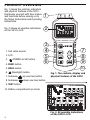
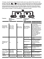
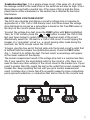
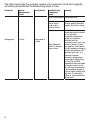
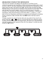
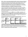
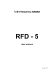
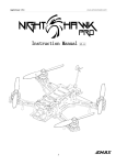
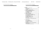
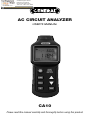
99 Washington Street
Melrose, MA 02176
Phone 781-665-1400
Toll Free 1-800-517-8431
Visit us at www.TestEquipmentDepot.com
AC CIRCUIT ANALYZER
USER’S MANUAL
CA10
Please read this manual carefully and thoroughly before using this product.
TABLE OF CONTENTS
Introduction . . . . . . . . . . . . . . . . . . . . . . . . . . . . . . . . . . . . . . . . . . . . 2
Key Features . . . . . . . . . . . . . . . . . . . . . . . . . . . . . . . . . . . . . . . . . . . 3
Safety Instructions . . . . . . . . . . . . . . . . . . . . . . . . . . . . . . . . . . . . . . 3
What's in the Box . . . . . . . . . . . . . . . . . . . . . . . . . . . . . . . . . . . . . . . 3
Product Overview . . . . . . . . . . . . . . . . . . . . . . . . . . . . . . . . . . . . . . . 4
Setup Instructions . . . . . . . . . . . . . . . . . . . . . . . . . . . . . . . . . . . . . . . 5
Install Batteries . . . . . . . . . . . . . . . . . . . . . . . . . . . . . . . . . . . . . 5
Attach Test Cable . . . . . . . . . . . . . . . . . . . . . . . . . . . . . . . . . . . . 5
Operating Instructions. . . . . . . . . . . . . . . . . . . . . . . . . . . . . . . . 5 – 13
Measuring Voltage Parameters . . . . . . . . . . . . . . . . . . . . . . 5 – 7
Measuring Voltage Drop. . . . . . . . . . . . . . . . . . . . . . . . . . . . 7 – 8
Measuring Conductor Impedance . . . . . . . . . . . . . . . . . . . 9 – 11
Testing Residual Current Devices (RCDs). . . . . . . . . . . . . . . . . 11
Testing Ground Fault Circuit Interrupters (GFCIs). . . . . . . . . . . 12
Testing Outlet Wiring . . . . . . . . . . . . . . . . . . . . . . . . . . . . 12 – 13
Other Functions . . . . . . . . . . . . . . . . . . . . . . . . . . . . . . . . . . . . 13
Specifications . . . . . . . . . . . . . . . . . . . . . . . . . . . . . . . . . . . . . . . . . 14
Operating & Maintenance Tips . . . . . . . . . . . . . . . . . . . . . . . . 14 – 15
Replacing the Batteries . . . . . . . . . . . . . . . . . . . . . . . . . . . . . . 14
Housekeeping Hints . . . . . . . . . . . . . . . . . . . . . . . . . . . . . 14 – 15
Warranty Information. . . . . . . . . . . . . . . . . . . . . . . . . . . . . . . . . . . . 15
Return for Repair Policy. . . . . . . . . . . . . . . . . . . . . . . . . . . . . . . . . . 15
INTRODUCTION
The CA10 is a special-purpose electrical tester designed to quickly identify and
locate single faults in low-voltage (120/240V) AC distribution lines (branch
circuits). It can also test the reliability and response time of GFCIs (ground fault
circuit interrupters) and RCDs (residual current devices) and check the wiring of
outlet sockets. The instrument’s ease of use, versatility and accuracy make it
the ideal electrician’s tool for preventing shocks, sparks, electrical fires,
equipment damage and poor equipment performance.
2
KEY FEATURES
• Measures a branch circuit’s line voltage, peak voltage, neutral-to-ground
voltage and frequency
• Calculates a circuit’s voltage drop in response to a 12A, 15A or 20A load in
order to check the circuit's integrity
• Measures the impedance of hot, neutral and ground conductors as well as
available short-circuit current (ASCC)
• Tests the reliability and response time of GFCIs (ground fault circuit
interrupters) and RCDs (residual current devices)
• Measures and displays True RMS values of all voltages except peak
voltages
• Identifies wiring configurations and detects wiring faults and missing
ground wires
• Compatible with 2- and 3-phase circuits
• 2.4 in. diagonal LCD with 30-second backlight
• Familiar menu/sub-menu operation
• Data hold and 30-minute auto power off functions
• Includes 1 ft. long test cable and standard tripod mount
• Powered by six “AAA” batteries (included)
• One-year limited warranty
SAFETY INSTRUCTIONS
! WARNING! !
Exercise caution when working with exposed wiring.
Do not use this instrument on circuits carrying voltages higher than 265VAC.
WHAT’S IN THE BOX
The CA10 comes in an illustrated box containing a soft canvas carrying case.
Inside the case are the instrument, a 20 in. (0.5m) long test cable, six “AAA”
batteries and this user’s manual.
3
PRODUCT OVERVIEW
Fig. 1 shows the controls, indicators
and physical features of the CA10.
Familiarize yourself with their names
and functions before moving on to
the Setup Instructions and Operating
Instructions.
1
Fig. 2 shows all possible indications
on the CA10’s LCD.
2
1. Test cable socket
2. LCD
3.
(POWER on/off) button
4. FUNC button
3
4
5
6
10
5. HOLD button
6.
7
8
9
(Backlight) button
7. Submenu
(up one line) button
8. Submenu
(down one line) button
Fig. 1. The controls, display and
physical features of the CA10
9. TEST button
10. Battery compartment (on back)
Fig. 2. All possible indications
on the CA10’s LCD
4
SETUP INSTRUCTIONS
INSTALL BATTERIES
The CA10 is powered by six “AAA” batteries (included).
To install the batteries:
1. Turn the unit over.
2. Remove the one Philips-head screw securing the battery compartment cover
(Figure 1, Callout 10) and set it aside.
3. Remove the battery compartment cover and set it aside as well.
4. Install the six supplied “AAA” batteries in the compartment, making sure to
match the polarity marks on the batteries with the marks stenciled inside the
compartment.
5. Replace the battery compartment cover and secure it with the Philips-head
screw.
ATTACH TEST CABLE
The test cable included with the CA10 has a plug compatible with Americanstyle 110VAC sockets. To attach the cable, plug it into the three-pronged socket
at the top of the CA10 (Fig. 1, Callout 1).
OPERATING INSTRUCTIONS
The symbols of the five main parameters/functions tested by the CA10—
voltage (V), voltage drop (Vd), conductor impedance (Z), RCD performance and
GFCI performance—are shown below as they appear on the bottom line of the
LCD. Use the FUNC button to move from any test to the test on its right. When a
test is selected, the border around its text icon is highlighted.
MEASURING VOLTAGE PARAMETERS
The CA10 can measure four parameters of an AC circuit voltage: 1) the True
RMS value of its phase voltage (L-N), 2) the True RMS voltage to earth (ground)
of its neutral line (N-E), 3) the peak value of the voltage (Peak), and 4) the
frequency of the voltage. Each of the first three parameters is measured and
displayed by choosing it from a submenu made available after the FUNC button
has been used to select V. By contrast, the frequency of each of the three
parameters is displayed on the top line of the LCD.
5
To begin, plug the free end of the test cable into any outlet of the circuit to be
tested. Press the
or
button to cycle through the three submenu options
in either direction, as shown in the figure below. The text icon of the parameter
being measured appears at the left of the display. The table below the figure
shows the normal measurement result for each of the four parameters. It also
lists possible causes of, and remedies for, abnormal results.
Actual Result
Remedy
Possible Cause
of Abnormal
Result
Circuit is overloaded Redistribute circuit load
Visually inspect all
connection points to detect
or rule out loose
108 to 132V
Phase Voltage
connections and defective
High impedance
Voltage is too
(120V circuit)
L-N (Nominal
point(s) in breaker outlets. If none are
high or too low box or circuit
Voltage ± 10%) 198 to 242V
apparent, locate points of
(240V circuit)
high impedance using an
infrared thermometer (IRT)
to detect their heat, or a
voltmeter to detect
excessive voltage drops
across parts. Repair or
replace defective
wiring/parts.
Supply voltage is too Consult your electricity
provider
high or too low
Find source of leakage
(a multi-point ground,
a device or piece of
Leakage current
Voltage to earth
equipment) and repair
>2V
>2V
of neutral line
or replace
N-E
Check and redistribute load
Three-phase
imbalance
Install spectral filter or take
other steps to reduce
Harmonic
interference
interference
Supply voltage is too Consult your electricity
Peak Voltage
provider
high or too low
(1.414 x Phase 153 to 185V
Voltage is too
(120V circuit)
Voltage, or TRMS 280 to 342V
Identify and relocate (if
Electronic
device
in
high or too low
value of Phase (240V circuit)
circuit is distorting necessary) the device
Voltage)
the AC sine wave
Frequency
60Hz (120V circuit) Frequency is too Supply frequency is Consult your electricity
50Hz (240V circuit) high or too low too high or too low provider
Parameter
6
Normal
Measurement
Result
Troubleshooting tips: 1) In a single-phase circuit, if the value of L-N is high
the leakage current in the neutral line or the earth line will also be high. 2) In a
three-phase circuit with a neutral line, if the value of N-E is high the threephase load is either unbalanced or the neutral line is affected by harmonic
interference.
MEASURING VOLTAGE DROP
The CA10 can calculate and display a circuit’s voltage drop in response to
application of a 12A, 15A or 20A dummy load. In all three cases, the voltage
drop displayed on-screen as a percentage is based on the True RMS value of
the drop on the circuit’s phase (live) line.
To select the voltage drop test, press the FUNC button until Vd is highlighted.
Then, for 120V circuits, press the
or
button to select the 15A or 20A
test (see figure below) to match the rating (maximum load) of the circuit.
Alternatively, select the 12A test for a 15A or 20A circuit to avoid tripping the
breaker of a “preloaded” circuit (i.e., a circuit serving other loads during the
load test). For 240V circuits, select the 12A test.
To begin, plug the free end of the test cable into the branch circuit’s outlet that
is furthest from the breaker box (distribution panel). Press the TEST button
(Fig. 1, Callout 9) to initiate the test. The test result, a percentage, will appear
on the lower readout of the display.
The normal measurement result of the voltage drop test is a number less than
8%. If your result for the most distant outlet in the circuit is <8%, there is no
need to check any other outlet(s) of the circuit closer to the breaker box. If your
result is greater than 8%, repeat the test on the outlet that is next-closest to the
breaker box. Keep repeating the test until you get a normal measurement
result. A voltage drop of more than 8% is usually caused by loose connections,
poorly spliced conductors, or conductors that are too thin for the circuit’s load.
7
The table below lists the possible causes of an abnormal result and suggests
remedies and additional troubleshooting steps to take.
Parameter
Normal
Measurement
Result
Actual Result
Possible Cause
Remedy
of Abnormal
Result
Circuit is overloaded Redistribute load
Conductors are too
thin for circuit
length and/or
circuit’s current
Voltage drop
0 to 8%
Voltage drop is
too high
High impedance
point(s) in breaker
box or circuit
8
Replace wiring with
heavier-gauge conductors
suitable for circuit’s rating
Visually inspect all
connection points to detect
or rule out loose
connections and splices,
broken or improperly
attached twist-on
connectors (wire nuts), and
defective outlets. If none
are apparent, locate points
of high impedance using an
infrared thermometer (IRT)
to detect their heat, or a
voltmeter to detect
excessive voltage drops
across parts. Alternatively,
run the Z-L and Z-N
impedance tests described
in the next section on the
hot and neutral conductors;
if one conductor produces
a much higher reading than
the other, it is defective.
Repair or replace defective
wiring/parts.
MEASURING CONDUCTOR IMPEDANCE
The CA10 can measure and display the impedance of all three circuit
conductors as well as one impedance-related parameter (available short-circuit
current, or ASCC). The three impedance values represent the impedances of the
phase (live) line (Z-L), the neutral line (Z-N), and the earth (ground) line (Z-E).
Available short-circuit current is a measure of the amount of current that would
pass through the circuit’s breaker if all of its conductors were to be shortcircuited. It is calculated as Phase Voltage/(Live line impedance + Neutral line
impedance). Using the terminology of the CA10: ASCC = (L-N)/(Z-L) + (Z-N).
Each of the four impedance parameters is measured and displayed by choosing
it from a submenu made available after the FUNC button has been used to
select Z.
To begin, plug the free end of the test cable into any outlet of the circuit to be
tested. Press the
or
button to cycle through the four submenu options
in either direction, as shown in the figure below. The text icon of the parameter
selected for measurement appears at the left of the display. To initiate any test,
press the TEST button.
9
The table below the figure shows the normal measurement result for each of
the four parameters. It also lists possible causes of, and remedies for, abnormal
results.
Parameter
Impedance of
live and neutral
conductors
(Z-L and Z-N)
Actual Result
Normal
Measurement
Result
<0.15Ω/m for
14AWG conductor
<0.1Ω/m for
12AWG conductor
Impedance is too
high
<0.03Ω/m for
10AWG line
<1Ω for personnel
safety
Impedance of
ground
conductor (Z-E)
10
<0.25Ω for
equipment safety
Impedance is
too high
Remedy
Possible Cause
of Abnormal
Result
Circuit is overloaded Redistribute circuit load
Conductor is too thin
for circuit length
and/or circuit’s
current rating
High impedance
point(s) in circuit or
breaker box
Replace wiring with
heavier-gauge conductors
suitable for circuit’s rating
Visually inspect all
connection points to detect
or rule out loose
connections and defective
outlets. If none are
apparent, locate points of
high impedance using an
infrared thermometer (IRT)
to detect their heat, or a
voltmeter to detect
excessive voltage drops
across parts. Repair or
replace defective
wiring/parts.
Conductor is too thin Replace wiring with
heavier-gauge conductors
for circuit length
suitable for circuit’s
and/or circuit’s
rating
current rating
Visually inspect all
connection points to detect
or rule out loose
connections and defective
outlets. If none are
apparent, locate points of
high impedance using an
infrared thermometer (IRT)
High impedance
point(s) in circuit or to detect their heat, or a
voltmeter to detect
breaker box
excessive voltage drops
across parts. Alternatively,
run the Z-L and Z-N
impedance tests on the
hot and neutral conductors;
if one conductor produces
a much higher reading
than the other, it is
defective. Repair or
replace defective
wiring/parts.
Notes: 1) Be sure any surge suppression system used is properly grounded so it
can continue to protect loads during transient overvoltage conditions. 2) Before
measuring any parameter, remove any heavy loads from the circuit to avoid
producing an inaccurate test result. 3) Before measuring Z-E, be sure to
disconnect any RCDs from the circuit to avoid triggering them. 4) A ground
connection is required to test the impedance of conductors in 2-wire systems.
TESTING RESIDUAL CURRENT DEVICES (RCDs)
The CA10 can measure how much current it takes to trip an RCD, and how
quickly it responds to an event that should cause a trip. It does so by placing a
resistance across the circuit’s live and ground lines, generating a current
between them. According to UL, it should take no more than 30mA to cause a
trip. The CA10 measures and displays the triggering current (in mA) and the
response time (in ms).
To select the RCD test, press the FUNC button until RCD is highlighted. Then
plug the free end of the test cable into any outlet equipped with an RCD. To
initiate the test, press the TEST button. During testing, the display will show the
word TEST on the top line. If the device fails to be triggered, the analyzer will
stop testing automatically after 6.5 seconds.
The table below shows the normal measurement result of RCD testing. It also
lists possible causes of, and remedies for, an abnormal result.
Parameter
RCD reliability
and response
time
Normal
Measurement
Result
RCD trips within
specified time
Actual Result
RCD is too slow
to trip
Possible Cause
of Abnormal
Result
RCD is installed
improperly
RCD fails to trip
RCD is defective
Remedy
Check that installation
complies with
manufacturer’s
requirement and relevant
standards
Repair or replace RCD
Notes: 1) Before testing, remove any heavy loads from the circuit to avoid
producing an inaccurate test result. 2) A ground connection is required to test
RCDs in 2-wire systems. 3) Another common name for a residual current device
(RCD) is a residual current circuit breaker (RCCB).
11
TESTING GROUND FAULT CIRCUIT INTERRUPTERS (GFCIs)
The CA10 can measure how much current it takes to trip a GFCI, and how
quickly it responds to a condition that should cause a trip. It does so by placing
a resistance across the circuit’s live and ground lines, generating a current
between them. According to UL, it should take no more than 5mA to trigger a
trip. The CA10 measures and displays the level of triggering current (in mA) and
the response time (in ms).
To select the GFCI test, press the FUNC button until GFCI is highlighted. Then
plug the free end of the test cable into any outlet equipped with a GFCI. To
initiate the test, press the TEST button. During testing, the display will show the
word TEST on the top line. If the device fails to be triggered, the analyzer will
stop testing automatically after 6.5 seconds.
The table below shows the normal measurement result of GFCI testing. It also
lists possible causes of, and remedies for, an abnormal result.
Parameter
GFCI reliability
and response
time
Normal
Measurement
Result
GFCI trips within
specified time
Actual Result
Remedy
GFCI fails to trip GFCI is defective
Check that installation
complies with
manufacturer’s
requirement and relevant
standards
Repair or replace GFCI
Possible Cause
of Abnormal
Result
GFCI is too slow GFCI is installed
to trip
improperly
Notes: 1) Before testing, remove any heavy loads from the circuit to avoid
producing an inaccurate test result. 2) A ground connection is required to test
GFCIs in 2-wire systems.
TESTING OUTLET WIRING
The CA10 automatically checks the wiring of any outlet it is plugged into. The
upper part of the display contains the following arrangement of three circles: N
stands for the neutral conductor, L for the live conductor, and E for the earth
(ground) conductor.
If the outlet’s wiring is normal, all three circles will be filled in, as shown in the
table on the next page. Different combinations of filled in (on), empty (off) and
flashing circles indicate specific faults.
12
Wiring Condition
Normal
No ground wire detected
Live and neutral conductors are reversed
Other conditions
Screen Display
L E N
Legend
Off
On
Flashing
Any wiring abnormality will prevent the CA10 from performing tests to the full
extent of its abilities. For example, in the absence of a ground wire the analyzer
can only measure the circuit’s phase voltage and voltage drop. Furthermore,
the CA10 cannot detect the voltage between two live lines, multiple concurrent
faults, or reversed neutral and ground conductors.
OTHER FUNCTIONS
Backlight. Pressing the
button while the CA10 is powered on turns on the
display backlight. If no button is pushed for 30 seconds, the backlight will turn
off automatically. You can turn off the backlight manually by pressing the
button again.
Auto Power Off (APO). A 30-minute APO function is automatically enabled
when the CA10 is powered on. When APO is enabled (indicated by a clock icon
( ) at the upper left of the display), if no button is pushed for 30 minutes the
CA10 will automatically power off to extend battery life.
To disable the APO function, press and hold the FUNC button while pressing the
button to power on the unit. The clock icon will not be displayed.
Data Hold. Pressing the HOLD button freezes measurements of voltage
parameters on the larger, lower readout. Other measurements cannot be held.
To release the hold, press the HOLD button again.
13
SPECIFICATIONS
Parameter or Component
Line Voltage
Peak Voltage
Line Frequency
Voltage Drop
Load Voltage
Neutral-to-Earth Voltage
Live, Neutral and
Ground Line Impedance
RCD Trip Time
RCD Trip Current
GFCI Trip Time
Display
Test Cable
Auto Power Off Trigger
Display Backlight Duration
Operating/Storage
Temperature
Dimensions
Weight (Without Batteries)
Power Source
Measurement
Measurement
Resolution
Range
Accuracy
85 to 265VAC
±1% of reading ± 0.2V
0.1V
121 to 374VAC ±1% of reading ± 0.2V
0.1V
45 to 65Hz
±1% of reading ± 0.2Hz)
0.1Hz
0.1 to 99.9%
±2.5% of reading ± 0.2%
0.1%
10 to 265V
±2.5% of reading ± 0.2V
0.1V
0 to 10VAC
±2.5% of reading ± 0.2V
0.1V
0 to 3Ω
±2.5% of reading ±0.02Ω
0.01Ω
>3Ω
NA
1 ms to 6.5 sec. ±1% of reading ± 2 ms
1 ms
30 to 37mA
±1% of reading ± 0.2mA
0.1mA
1 ms to 6.5 sec. ±1% of reading ± 2 ms
1 ms
Backlit 2.4 in. (61mm) diagonal LCD
12 AWG diameter, 12 in. (305mm) long
30 minutes of inactivity
30 seconds
32° to 122°F (0° to 50°C) ) @ <80% RH
7.6 x 3.1 x 1.5 in. (193 x 78 x 39mm)
10.4 oz. (295g)
Six “AAA” batteries
OPERATING & MAINTENANCE TIPS
REPLACING THE BATTERIES
When the
(low battery) icon appears on the top line of the display, it’s time
to replace the unit’s six “AAA” batteries. Follow the instructions on p. 5 for
opening and closing the battery compartment and installing the batteries.
HOUSEKEEPING HINTS
DO NOT expose the CA10 to:
• Direct sunlight
• High humidity or temperatures (above 104°F/40°C during operation or
140°F/60°C in storage)
• Corrosive or explosive gas
• Excessive dust
• Strong mechanical vibration or stress (dropping, for example) or
electromagnetic radiation
14
If the instrument has been exposed to extreme temperatures, allow several
hours for it to acclimate to your local conditions before using it.
Do not open the housing of the unit. Doing so voids its limited warranty and
could disable its safety circuitry.
You may clean the housing of the CA10 with a soft, clean cloth and water or a
mild detergent. Never use benzene, alcohol, acetone, ether, ketone, paint
thinner, gasoline or an organic solvent. After cleaning, dry the CA10 thoroughly
with a clean cloth before using it again.
WARRANTY INFORMATION
General Tools & Instruments’ (General’s) CA10 AC Circuit Analyzer is warranted
to the original purchaser to be free from defects in material and workmanship
for a period of one year. Subject to certain restrictions, General will repair or
replace this instrument if, after examination, the company determines it to be
defective in material or workmanship.
This warranty does not apply to damages that General determines to be from
an attempted repair by non-authorized personnel or misuse, alterations, normal
wear and tear, or accidental damage. The defective unit must be returned to
General Tools & Instruments or to a General-authorized service center, freight
prepaid and insured.
Acceptance of the exclusive repair and replacement remedies described herein
is a condition of the contract for purchase of this product. In no event shall
General be liable for any incidental, special, consequential or punitive damages,
or for any cost, attorneys’ fees, expenses, or losses alleged to be a
consequence of damage due to failure of, or defect in any product including,
but not limited to, any claims for loss of profits.
Test Equipment Depot - 800.517.8431 - 99 Washington Street Melrose, MA 02176
TestEquipmentDepot.com