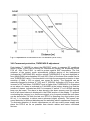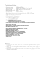
1
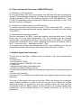
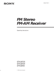
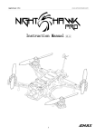
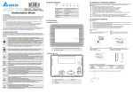
Radio frequency detector RFD - 5 User manual Version 2.0 User manual RFD-5 is an advanced broadband high sensitive radio frequency detector. All parameters of RFD-5 are optimized for detection of all type wireless bugs including the latest technology. RFD-5 can be used to detect digitally encoded signals, spread spectrum, hopping and pulse transmissions, and signals at extremely high frequencies up to 25GHz. Since the device is predetermined for the top professional security the technical and operational training is recommended. The latest version 2.0 offers increased dynamic range and selectable logarithmic or exponential detection. I. Controls, inputs, outputs “1” LCD display 2 x 12 characters “2” Main switch ON / OFF “3” Audio alarm switch AUDIO / OFF “4” Button UP “5” Button DOWN “6” Button FILTER / DELETE “7” Button MODE “8” LED CHARGE (charging indicator) “9” Connector EARPHONE (earphone stereo type 32 ohm) “10” Connector EXT.POWER (external power and charge) “11” Connector EXT.PROBE “12” Telescope antenna In the following text the numbered notation (“1” to “12”) shall be used. Some buttons have multiple functions depending on the current mode of the device: button MEASURE: PROTECT: LISTING: -------------------------------------------------------------------------------------------------------------“4” UP sensitivity & volume + threshold + alarm list + “5” DOWN sensitivity & volume threshold alarm list – “6” FILTER/DELETE RF filter switch RF filter switch alarm delete “7” MODE mode change in order M: P: L: M: .....etc. II. Power ON, battery check and charging After switching ON the device performs a self test; LCD “1”shortly displays SW version and if “3” is in AUDIO the melody tone can be heard. After the self test the device goes to the basic mode MEASURE M:W LOG. I 000 M:W LOG 000 M: = measure, W = wide filter 0.5MHz to 25GHz, LOG = logarithmic detection, 000 = signal level is 0 The measured RF level is signalized by a bar graph and two numerical values: CURRENT and PEAK. The PEAK value represents a maximal RF level over last 6s. 2 The device constantly measures the battery health status. If LOW BATT! is periodically displayed at the bottom display line, the battery should be replaced or the accumulator should be charged. WARNING: deeply discharged battery can cause either no function or displaying M:W LOG only with no button responding. 9V battery or accumulator is below the bottom lid which can be removed by the nail to the cut in the bottom lid. Be careful when inserting the battery and closing the lid not to damage the battery wires and to set the lid properly. It is recommended to use a 9V NiMH accumulator which can be recharged by an external power supply 12 to 20V DC with + pole on the central pin. Charging time of the fully discharged accumulator is 14 hours. Longer charging times are allowed since an internal regulation circuit avoids accumulator overcharging. III. Measurement, sweeping, bug detection Adjust basic mode MEASURE, filter M:W LOG and push out the telescope antenna. Slowly move the RFD-5 and properly check entire room and all objects inside the swept area. The listening device is usually ingeniously disguised. A rapid increase of the RF field can be observed at a spot or close to an object signalizes a potential RF eavesdropping. During sweeping use the earphone (output “9” EARPHONE) and listen to the demodulated signal. Often a bug can be heard in the earphone, but using earphones primarily helps to recognize legal signals like TV and radio broadcasting or GSM. If switch “3”is in AUDIO state the Geiger click audio indicator is enabled and helps the user to find the strongest signal by increasing the click frequency with an increase of RF signal level. Characteristics of typical signals: a) TV carrier: 50 Hz noise, usually stronger close to windows b) Broadcast: voice or music c) GSM: cell – data and tone about 2 kHz, mobile – pulses depending on talking d) Dangerous signals: not specified in a) to c), their maximum has to be found. It is necessary to prove if the signal is originated in the swept area or if the signal is incoming from outdoor. Adjustment of RF sensitivity, audio volume and change of detection mode Default setting LOG, logarithmic detection offers large dynamic range 43dB. The disadvantage of logarithmic detection is a large compression of strong signals. Even if the antenna is shorten the signal maximum close to the bug can be flat. In case of a strong RF background or close to the transmitter set the exponential detection and appropriate attenuation -0dB, -10dB, -20dB, -30dB or -40dB by button "5" DOWN (back by button "4" UP). The average RF level should be between 000 to about 150. In the exponential detection mode (settings -0dB to -40dB) the increase of displayed signal level is very sharp close to the transmitter. The attenuation is also regulating audio volume in the earphone. Example of setting: l 000 M:H-20dB 000 M: = measure, H= filter Hf detection range 30MHz to 25GHz, -20dB = exponential detection with attenuation -20dB, 000 = signal level 0 3 IV. Filters and special functions in MEASURE mode a) Elimination of HF interference In some areas there are very strong signals from MW and SW radio broadcasting. Strong HF broadcasting interference can easily obscure the listening device which is usually operating on VHF or UHF frequency. By button “6”FILTER adjust M:H.... Filter HF OFF is suppressing frequencies below 30 MHz and the sensitivity for VHF, UHF and SHF remains unchanged. b) Localization of listening device on SHF frequency To localize transmitter using frequency above 3 GHz select filter M:S... which is disconnecting the telescope antenna and the signals are received just via the top lid of the RFD-5. c) Recommended sweeping procedure Start the sweeping in the M:W... mode and carefully check the entire area. If in the whole area is a low radio background (<10), the sweeping can be finished. Unfortunately the background levels in cities are usually much higher. To eliminate background interference and to make sweeping as accurate as possible start in M:W..., continue in M:H... and finally use M:S... filter. In an object with stronger radio background and for exact localization of a bug set exponential detection and manually select appropriate attenuation (-XXdB). V. Multiple signal level indication The RF level is indicated in different forms to provide a fast and comprehensive indication: 1) Instant level: - bar indicator RF LEVEL - numerical indicator CURRENT 251 levels 2) Peak level: - delayed bar indication of the highest level - numerical indication PEAK 251 levels *The delayed bar and the PEAK are indicating the highest level measured during last 6 sec. 3) Geiger click indication If the switch “3” is in AUDIO the audible Geiger click indication helps to find the signal maximum. The strip of the highest level and the number PEAK are making the localization easier. Delayed indication of peaks is also the only way how to detect and localize digital pulse bugs. In practice the user can optimally sweep the area and just occasionally look at the PEAK indicator. No local maximum of a signal or digital pulse transmission can be missed because it is always memorized for 6s from its appearance. 4 VI. Sensitivity, frequency range, bug distance and power calculation RFD-5 is very sensitive detector with extremely large frequency range, detecting real listening devices up to 25 GHz. Fig.1 depicts the ability of RFD-5 to detect various radio listening devices for an indication RF LEVEL = 5 and the distance of 5 cm from the signal source. From the graph we can observe that effective radiated power (ERP) 1uW (1000x less than typical bug is radiating) can be detected up to 10GHz. A more realistic 1mW device can be detected up to 25GHz! Fig.2 depicts a dependence of indicated LEVEL on the DISTANCE for three typical bug output powers (ERP) in logarithmic detection mode M:W LOG. Since close to the transmitter is the electromagnetic field very non-homogeneous the highest measured level is valid at the optimal position and length of the RFD-5 antenna. The plots at fig.2 are valid in the frequency range 80-500 MHz (typical bug frequencies). If the transmitter distance is known the radiated power (ERP) can be read from the graphs and consequently it is possible to deduce the theoretical range of the listening device in the real environment. Fig.1: Ability to detect various radio listening devices (Frequency / ERP) VII. VIP operative sweeping The security service specialist sweeps the office and creates a written protocol containing maximum levels measured at specific places in the VIP office. The VIP before or better during a meeting checks if there is a remarkable increase of LEVEL comparing with originally listed values at the specified places. Any level increase especially close to mobile phones (GSM) should be carefully examined. An example of a written protocol made by a specialist for VIP operative sweeping: mode M:W LOG, ANTENNA full length, window max.65, desk max.40, TV corner max.50, etc. 5 Fig.2: Dependence of indicated LEVEL on distance (M:W LOG) VIII. Permanent protection, THRESHOLD adjustment Push button “7” (MODE) to select the PROTECT mode. In common RF conditions adjust P:Wide, in the case of strong HF interference (usually SW broadcast) select P:Hf off filter. Filter P:Shf is used to protect against SHF transmitters. The first selection of the protect mode automatically initiates storing of the background (indicated by CHECKING BG) and the optimal THRESHOLD is set and displayed in form tNNN (NNN varies between 003 and 250). Each of the three filter modes has its own THRESHOLD value. If the threshold is too high the permanent protection is less sensitive (if NNN = 250 no signal can cause an alarm). The threshold can be manually changed by buttons “4” (UP) and “5” (DOWN). Activation of RF bug or other increase of RF field when CURRENT level is higher than THRESHOLD is registered as an alarm. An alarm is indicated by P:ALARM! at the bottom display line and the number of alarms indicated as aNN is increased. If switch “3” is in AUDIO warning beep can be heard. The alarm is also stored in the alarm memory and the highest level of all stored alarms is displayed in the PEAK section of the display. To prevent overloading the memory by a continuous signal or by frequent pulses the next alarm can be stored after 70s from the last one. RFD-5 is detecting very short pulses (over 80 us), it is important to detect some advanced digital systems. This speed can cause detection of different disturbances like switching electric appliances, lamps etc. To eliminate detection of electric disturbances do not use mains power supply and place the RFD-5 as far as possible from electric cables and mains connected devices. 6 Example of LCD indication in PROTECT mode: a54 t031 015 NN=54 registered 54 alarms, threshold NNN = 031, signal = 015, P:Wide 158 filter WIDE, highest registered level in memory = 158 IX. VIP permanent protection Adjust length of telescope antenna to 4 – 10 cm. Put the RFD-5 as close as possible to negotiation table. Adjust protect mode P:Hf off. Do not use mobile phones during checking background (change from mode M: to P:)! The optimal difference between tNNN and the CURRENT value is 15. A higher difference decreases sensitivity but increases false alarm resistance. The threshold tNNN can be changed by UP and DOWN buttons. Use audio warning switch “3” in AUDIO to be informed about a danger. X. Detection of pulse transmitters Ensure permanent talk (sound) in the checked area to force a hidden pulse transmitter to transmit as much data as possible. In the measure mode of RFD-5 read the display at least once per 6s not to miss any pulse. Systematically move the RFD-5 to find the signal maximum. The PROTECT mode shall be used if the transmitter is transmitting non-periodically or in longer periods. XI. Searching of ALARM memory - LISTING Up to 16 alarms can be stored in the alarm memory. The alarm records are displayed in LISTING mode (L:ALARM). The alarms are listed by buttons “4” UP or “5” DOWN. The alarms are sorted from the oldest to the newest. If more than 16 alarms appeared the last alarm record (16/16) is overwritten by the latest record. Example of LCD indication in LISTING mode: -10:29 15/16 L:ALARM 012 15th of 16 alarms was recorded before 10 hours 29 minutes and its signal level was 012 XII. Detection of SHF frequencies 3 – 25 GHz For very high frequencies, particularly above 3 GHz the telescopic antenna loses efficiency. For SHF detection it is better to fully push the antenna into RFD-5 and adjust the M:S... filter. The active part of RFD-5 is the front lid. The strongest level is detected if the front lid is beaming to the source of SHF signal. XIII. External probe For sweeping high ceilings or hardly reachable places connect the external probe. The probe disconnects the internal detector. RFD-5 functionality remains the same, only filter selection W / H / S (wide, HF, SHF) is irrelevant. 7 Technical specification - Frequency range: - Typical sensitivity: - Dynamic range: - Detectable pulse width: - HF filter (Hf off): 0.5MHz to 25GHz 0.06uW ERP (400MHz / 5 cm / level =5) 43dB logarithmic, 60dB exponential >80us -26dB on 10MHz - Sensitivity and volume control in exponential mode : 40dB, 10dB steps - Geiger click indication: internal buzzer - LCD indicator (2 x 12 characters) - Instant signal strength indication: - bar indicator (39 levels) - numerical (251 levels) - Peak level indication: - delayed bar indicator (24 levels) - delayed numerical indication (251 levels) - Level refresh: level increase 1ms, level decrease 6s (delayed indication) - Alarm counter: 99 events - Alarm memory: 16 events, including time and signal level - Next alarm record delay: 70s - Built in telescope antenna: adjustable from 1 to 37cm - Earphone: stereo type, 32ohm - Battery low indication: below 7V - External power supply: 12-20V DC unstabilized - Accumulator recharge circuit: optimized for NiMH - Battery: 9V model 6F22, or 9V accumulator - Current consumption: 3.5 to 6 mA - Mechanical size: 150 x 60 x 31 mm - Weight: 295g Warning! Do not open the device, there are no elements adjustable without special equipment Never use non-rechargeable alkaline batteries if the mains power supply is connected Short click in the earphone each 9 sec. is no fault or any signal, it is a self calibration of the detector 8