1
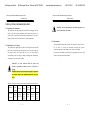
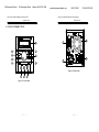
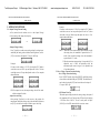
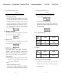
Test Equipment Depot 99 Washington Street Melrose, MA 02176-6024 www.testequipmentdepot.com PSS-3203/2005 PROGRAMMABLE POWER SUPPLY 800-517-8431 781-665-0780 FAX PSS-3203/2005 PROGRAMMABLE POWER SUPPLY USER MANUAL USER MANUAL CONTENTS PAGE 1. PRODUCT INTRODUCTION................................................. 1 1-1. Description… … … … … … … … … … … … … … … … … … 1 1-2. Feature… … … … … … … … … … … … … … … … … … … ... 1 2. TECHNICAL SPECIFICATIONS… … … … … … … … … … 3 3. PRECAUTIONS BEFORE OPERATION… … .… … … … ... 5 3-1. Unpacking the Instrument… … … … … … .… … … … .… . 5 3-2. Checking the Line Voltage… … … … … … … ..… … … … . 5 3-3. Environment… … … … … … … … … … … … … … ..… … ... 6 4. PANEL INTRODUCTION… … … … … … … … ..… … … … ... 7 5. OPERATION METHOD… … … … … … … … … … … … ...… . 10 5-1. Output Voltage/Current Setting… … … … … … … ..… … 10 5-2. Over Voltage/Current Protection Setting… … … … … ... 11 5-3. The Display Contrast Setting.… … … … … … … … … … .. 12 5-4. The Buzzer Setting… … … … … … … … … … … … … … … 12 5-5. GPIB/RS-232 Interface Setting… … … … … … … … … … 12 5-6. The Maximum Setting Value… … … … … … … … … … ... 13 5-7. Test Lead… … … … … … … … … … … … … … … … … … ... 13 5-8. The Setting for the GPIB and RS232 Interface… … … .. 13 6. 7. iii MAINTENANCE… … … … … … … … … ..… … … … … … … .. 6-1. Fuse Replacement… … … … … … … … … … … … … … … . 6-2. Line Voltage Conversion… … … … … … … … … … … … .. 6-3. Adjustment and Calibration… … … … … … … … … … … 6-4. Cleaning… … … … … … … … … … … … … … … … … … … THE SYSTEM DIAGRAM AND DESCRIPTION… … … .. 7-1.Block Diagram… … … … … … … … … … … … … … … … ... 7-2.The Operation of the whole circuit… … … … … … … … ... i 14 14 14 15 18 19 19 20 Test Equipment Depot 99 Washington Street Melrose, MA 02176-6024 PSS-3203/2005 PROGRAMMABLE POWER SUPPLY www.testequipmentdepot.com 800-517-8431 781-665-0780 FAX PSS-3203/2005 PROGRAMMABLE POWER SUPPLY USER MANUAL USER MANUAL SAFETY TERMS AND SYMBOLS FOR UNITED KINGDOM ONLY These terms may appear in this manual or on the product: NOTE: This lead/appliance must only be wired by competent persons WARNING. Warning statements identify condition or WARNING: THIS APPLIANCE MUST BE EARTHED practices that could result in injury or loss of life. IMPORTANT: The wires in this lead are coloured in accordance with the following code: CAUTION. Caution statements identify conditions or practices that could result in damage to this product or other property. Green/ Yellow: Blue: Brown: Earth Neutral Live (Phase) The following symbols may appear in this manual or on the product: As the colours of the wires in main leads may not correspond with the colours marking identified in your plug/appliance, proceed as follows: The wire which is coloured Green & Yellow must be connected to the Earth terminal marked with the letter E or by the earth symbol DANGER ATTENTION Protective Earth (ground) Frame or Chassis or coloured Green or Green & Yellow. High Voltage refer to Manual Conductor Terminal The wire which is coloured Blue must be connected to the terminal which is marked with the letter N or coloured Blue or Black. Terminal Terminal The wire which is coloured Brown must be connected to the terminal marked with the letter L or P or coloured Brown or Red. If in doubt, consult the instructions provided with the equipment or contact the supplier. ii iii Test Equipment Depot 99 Washington Street Melrose, MA 02176-6024 PSS-3203/2005 PROGRAMMABLE POWER SUPPLY www.testequipmentdepot.com 800-517-8431 PSS-3203/2005 PROGRAMMABLE POWER SUPPLY USER MANUAL USER MANUAL This cable/appliance should be protected by a suitably rated and approved HBC mains fuse: refer to the rating information on the equipment and/or user instructions for details. As a guide, cable of 0.75mm2 should be protected by a 3A or 5A fuse. Larger conductors would normally require 13A types, depending on the connection method used. Any moulded mains connector that requires removal /replacement must be destroyed by removal of any fuse & fuse carrier and disposed of immediately, as a plug with bared wires is hazardous if a engaged in live socket. Any re-wiring must be carried out in accordance with the information detailed on this label. iv v 781-665-0780 FAX Test Equipment Depot 99 Washington Street Melrose, MA 02176-6024 PSS-3203/2005 PROGRAMMABLE POWER SUPPLY www.testequipmentdepot.com 800-517-8431 781-665-0780 FAX PSS-3203/2005 PROGRAMMABLE POWER SUPPLY USER MANUAL USER MANUAL 3.PRECAUTIONS BEFORE OPERATION WARNING. To avoid personal injury, disconnect the power cord 3-1.Unpacking the Instrument The product has been fully inspected and tested before shipping from the before removing the fuse holder. factory. Upon receiving the instrument, please unpack and inspect it to check if there is any damage caused during transportation. If any sign of damage is found, notify the bearer and/or the dealer immediately. 3-3.Environment The normal ambient temperature range of this instrument is from 0 ° to 40 °C 3-2.Checking the Line Voltage The product can be applied by any kind of line voltages shown in the table (32° to 104°F). To operate the instrument exceeding this specific below. Before connecting the power plug to an AC line outlet, make sure temperature range may cause damage to the circuits of instrument. the voltage selector of the rear panel is set to the correct position Do not use the instrument in a place where strong magnetic or electric field corresponding to the line voltage. It might be damaged the instrument by exists as it may disturb the measurement. connecting to the wrong AC line voltage. WARNING. To avoid electrical shock the power cord protective grounding conductor must be connected to ground. AVERISS: Pour éviter les chocs électriques, le fil de terre du cordon secteur doit impérativement être relié à la terre. When line voltages are changed, replace the required fuses shown as below: Model Line Range Fuse 90-110V 108-132V T3A 250V T3A 250V voltage PSS-3203 PSS-2005 100V 120V 5 Line voltage 220V 230V Range Fuse 198-242V 216-253V T1.6A 250V 1.6A 250V 6 Test Equipment Depot 99 Washington Street Melrose, MA 02176-6024 PSS-3203/2005 PROGRAMMABLE POWER SUPPLY www.testequipmentdepot.com 800-517-8431 781-665-0780 FAX PSS-3203/2005 PROGRAMMABLE POWER SUPPLY USER MANUAL USER MANUAL 4. PANEL INTRODUCTION GPIB R CV PROGRAMMABLE POWER SUPPLY LABEL PSS-3203 OUT 0 .000 33 .00V ETL 14 A 2 15 POWER LOCAL FUSE RATING 10 MENU 1 9 F C 6 100V 120V 220V 230V T 3A 250V T 1.6A 250V 190 WATTS 235 VA 50/60 Hz AC SELECTOR 8 AC 100V V SET ISET 120V 220V OUTPUT 12 7 ENTER 11 OUTPUT 0 32V 0 DISCONNECT POWER CORD REPLACE FUSE AS SPECIFIED BEFORE REPLACING FUSE 3A Figure 4-2 Rear Panel 4 5 3 Figure 4-1 Front Panel 7 8 230V 13 Test Equipment Depot 99 Washington Street Melrose, MA 02176-6024 PSS-3203/2005 PROGRAMMABLE POWER SUPPLY USER MANUAL 1. 2. Power Switch Display 3. 4. 5. 6. 7. +Output Terminal -Output Terminal GND Terminal Rotary Encoder V Set/I Set (ENTER) 8. F/C 9. MENU 10. LOCAL 11. Output 12. AC Power So cket 13. AC Select Switch 14. Cooling Fan 15 Interface Connect the AC power, then press power switch. Indicate the s etting of voltage/current value, output voltage/current value and the status of setting and output. Positive output terminal. Negative output terminal. Connect the ground terminal to chassis. Wheel knob. The key for switch over output voltage and output current setting. ENTER: The knob for value input or setting confirmation. The knob for switching over coarse and fine adjustment. The category of function setting (Output, OVP, OCP, Contrast, Buzzer, Interface.) PS. After switching to the picture of function setting category, if there is no further setting action within 4 to 5 seconds, the system will return to previous setting picture or output display picture. Clear REMOTE control mode, and replace with panel control. PS. Get into calibration mode by pressing the knob more than 5 seconds uninterruptedly, Turn on or off output by pressing the knob. AC power input terminal. Switch Voltage to 100V, 120V, 220V or 230V, 50/60Hz. A cooling fan. GPIB or RS-232C communication interface. 9 www.testequipmentdepot.com 800-517-8431 781-665-0780 FAX Test Equipment Depot 99 Washington Street Melrose, MA 02176-6024 PSS-3203/2005 PROGRAMMABLE POWER SUPPLY USER MANUAL 5. OPERATION METHOD 5-1. Output Voltage/Current Setting At first, ensure that the window now is at the Output Voltage/ Current setting or the output value display. or --Output Voltage Setting: Press [Vset/Iset] to set the cursor to the position for voltage input, and modify the setting value with wheel knob. Right now, can use [F/C] to switch over the input of 1V step or 10mV step. Example: If want to set the voltage as 12.34V, first using the [F/C] knob to switch the cursor to 10mV step and adjust the value to 34, then switch the cursor to 1V step and adjust the value to 12 to complete the modification. >> >> PS. If the output is on now, the output voltage value will be varied with the setting of the knob. --Output Current Setting: After pressing [Vset/Iset] to set the cursor to the position for current input, modify the setting value with wheel knob. Right now, use [F/C] to switch over the input of 100mA step or 1mA step. 10 www.testequipmentdepot.com 800-517-8431 781-665-0780 FAX PSS-3203/2005 PROGRAMMABLE POWER SUPPLY USER MANUAL Example: If want to set the current as 1.234A, first using the [F/C] knob to switch the cursor to 1mA step and adjust the value to 34, then switch the cursor to 100mA step and adjust the value to 12 to complete the modification. >> >> Note: 1. When the load current through output terminal exceeds the setting value, the instrument is operated in the C.C. mode, if not exceeds the setting value, the instrument is operated in the C.V. mode. 2. When the maximum output voltage is larger than 36V, its adjustable step is 20mV the minimum while the maximum output current is larger 3A, its adjustable step is 2mA the minimum. 5-2.Over Voltage /Current Protection Setting --Over Voltage Protection Setting: Set to OVP SET window by pressing [MENU], modify the setting value with the wheel knob and press [ENTER]. The modification can be done by using the [F/C] knob to switch over the input of 1V step or 10mV step. --OVP Status Clear Up: When the output voltage exceeds the setting voltage, the output of the instrument will be off and get into OVP mode by displaying “OVP Error. Press “LOCAL” to reset” on the panel. Just press [LOCAL] to clear OVP status and back to previous status. 11 Test Equipment Depot 99 Washington Street Melrose, MA 02176-6024 PSS-3203/2005 PROGRAMMABLE POWER SUPPLY www.testequipmentdepot.com 800-517-8431 PSS-3203/2005 PROGRAMMABLE POWER SUPPLY USER MANUAL --Over Current Protection Setting: Set to OCP SET window by pressing [MENU], Turn on/off the OCP with the wheel knob and press [ENTER]. If OCP is on, when the output current equals or exceeds the curr ent value setting, the output of the instrument will be off and get into over current protection mode by displaying “OCP Error. Press “LOCAL” to reset” on the display. Just press [LOCAL] to clear OCP status and back to previous status. 5-3. The Display C ontrast Setting Set to Contrast Set window by pressing [MENU], modify its setting value with the wheel knob and press [ENTER]. 5-4. The Buzzer Setting Set to Buzzer Set window by pressing [MENU], turn on or off the buzzer with the wheel knob, then press [ENTER]. 5-5.GPIB/RS232 Interface Setting Set to Interface window by pressing [MENU]. If the GPIB is displayed, the Address value window will be appeared, if the RS-232 is displayed, the Baud Rate window will be appeared, then using the wheel knob to modify the value and press [ENTER] to complete the setting. Note: The system will detect the interface used at present automatically, and switch the detected interface over the setting interface of GPIB or RS-232. Example: 1) If want to set the GPIB address value to 15: Set to interface window by pressing [MENU], and adjust the address value to 15 with the wheel knob and press [ENTER] to 12 781-665-0780 FAX USER MANUAL complete the setting. 2) If want to set the RS-232 Baud Rate to 9600: Set to interface window by pressing [MENU], and adjust the Baud Rate value to 9600 with the wheel knob and press [ENTER] to complete the setting. 5-6. The Maximum Setting Value MODEL ITEM PSS-3203 PSS -2005 Output Voltage 33.00V 21.00V Output Current Over-voltage 3.100A 34.00V 5.200A 22.00V 5-7.Test Lead MODEL ITEM PSS -3203 PSS-2005 Current 3A Test Lead Current 4A -10A Test Lead 5-8. The setting for the GPIB and RS232 Interface If you have PSS-series programmable power supply, use the GPIB or RS-232 interface, please refer to the PSS-series Programmer Manual for more details. 13 Test Equipment Depot 99 Washington Street Melrose, MA 02176-6024 PSS-3203/2005 PROGRAMMABLE POWER SUPPLY www.testequipmentdepot.com 781-665-0780 FAX PSS-3203/2005 PROGRAMMABLE POWER SUPPLY USER MANUAL steps. 800-517-8431 USER MANUAL At present, the window will indicate the progress of OVP calibration. When the calibration is completed, it will jump out of the window. [Step 3.1] Now input the current value (Max.) measured by the DMM with the knob and press [ENTER]. During the current value input, use the [F/C] button to switch over the input of 100mA range (100mA/step) or 1mA range (1mA/step). Note: The DMM selected for the measurement must have the resolution of four digits of the decimal point at least (0.1mA). Also the input value is to take three digits of decimal point of effective value (1mA) and run off the rest. [Step 3.2] Now input the current value (Min.) measured by the DMM with the knob and press [ENTER]. During the current value input, use the [F/C] button to switch over the input of 100mA range (100mA/step) or 1mA range (1mA/step). Note:The DMM selected for the measurement must have the resolution of four digits of the decimal point at least (0.1mA). Also the input value is to take three digits of decimal point of effective value (1mA) and run off the rest. [Step 4] Switch the Calibration selection window to O.V.P. calibration item with the knob and press [ENTER] getting into O.V.P calibration steps. [Step 5] When above calibration steps has been confirmed correctly, switch the calibration selection window to SAVE window with the knob and press [ENTER] to complete the whole calibration procedures. [Step 6] If the calibration procedure is not necessary to be stored, just switch the calibration selection window to Exit window and press [ENTER] to leave the calibration procedure. 6-4. Cleaning To clean the power supply, use a soft cloth dampened in a solution of mild detergent and water. Do not spray cleaner directly onto the instrument, since it may leak into the cabinet and cau se damage. Do not use chemicals containing benzine, benzene, toluene, xylene, acetone, or similar solvents. Do not use abrasiv e cleaners on any portion of the instrument. [Step 4.1] 18 19