1
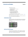
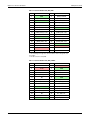
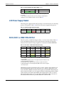
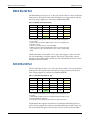
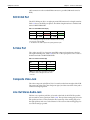
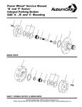
I/O Expansion
H Card (HIOX_BW)
User Manual
Developing Embedded Applications & Products
Utilizing Motorola PowerPC™ 8xx Processors
700M0010RA0
2
700M0010RA0
I/O Expansion, H Card
Notice
This manual in whole or in part, is to be considered the intellectual property of
Embedded Planet. The manual and all information explained and derived there
from are protected by the license to which you agreed upon opening this package.
This document contains confidential information and is intended for the sole
purpose of the end user to develop applications on the H Card product offered by
Embedded Planet, LLC. Neither the document, nor reproductions of it, nor
information derived from it is to be given to others, nor used for any other
purpose other than for H Card applications. No use is to be made of it which is or
may be injurious to Embedded Planet, LLC and no use is to be made of it other
than for H Card applications.
Trademarks
Embedded Planet, PlanetTrack, Linux Planet, Blue Planet, RPX Lite, and RPX
LICC are trademarks or registered trademarks of Embedded Planet.
PowerPC is a trademark of International Business Machines.
All other names and trademarks are the property of their respective owners.
700M0010RA0
3
I/O Expansion, H Card
4
700M0010RA0
I/O Expansion, H Card
Contents
Chapter 1 Introduction .......................................................................................................... 7
Functions .........................................................................................................................................7
Mix and Match Criteria and Exclusions .....................................................................................7
850/823 Based Product ..........................................................................................................7
860/821 Based Product ........................................................................................................10
Miscellaneous Restriction ....................................................................................................10
Video .......................................................................................................................................10
LCD .........................................................................................................................................11
Matrix ......................................................................................................................................11
How to Use This Manual ............................................................................................................11
Reference Documents ..................................................................................................................11
Chapter 2 Setup ................................................................................................................... 13
Strapping .......................................................................................................................................13
Chapter 3 Connectors and Headers ................................................................................... 15
JTAG Interface Header ................................................................................................................15
Flat Panel Interface Headers .......................................................................................................15
LCD Power Supply Header ........................................................................................................17
SCC3, SCC1, or SMC1 RS-232 Port ............................................................................................17
SMC2 RS-232 Port ........................................................................................................................18
SCC2 RS-232 Port .........................................................................................................................18
SCC2 IrDA Port ............................................................................................................................19
S-Video Port ..................................................................................................................................19
Composite Video Jack ..................................................................................................................19
Line Out Stereo Audio Jack ........................................................................................................19
Line In Stereo Audio Jack ...........................................................................................................20
Touch Panel Interface Header ....................................................................................................20
Bus and I/O Interface Expansion Connectors .........................................................................21
List of Figures
No.
1-1.
1-2.
700M0010RA0
Title
Page
H Card Board - Top View ................................................................................................8
H Card Board - Bottom View ..........................................................................................9
5
I/O Expansion, H Card
List of Tables
No.
1-1.
1-2.
2-1.
3-1.
3-2.
3-3.
3-4.
3-5.
3-6.
3-7.
3-8.
3-9.
3-10.
3-11.
3-12.
3-13.
6
Title
Page
Hardware Features ...........................................................................................................7
Reference Documents.....................................................................................................11
Strapping..........................................................................................................................13
JTAG Header Pinout (P10) ............................................................................................15
Flat Panel Header Pinout (P8A) - NEC........................................................................16
Flat Panel Header Pinout (P8B) - SHARP ...................................................................16
LCD Power Supply Header Pinout (P8C)...................................................................17
SCC3, SCC1, or SMC1 RS-232 Header Pinout (P4) ....................................................17
SMC2 RS-232 Header Pinout (P3) ................................................................................18
SCC2 RS-232 Header Pinout - (P5) ...............................................................................18
SCC2 IrDA Port Pinout (P6) ..........................................................................................19
S-Video Port Pinout (P7)................................................................................................19
Stereo Output Jack (P12)................................................................................................20
Stereo Input Jack (P11) ...................................................................................................20
Microtouch Touch Interface Pinout (P9) .....................................................................20
Dynapro Touch Interface Pinout (P9) ..........................................................................20
700M0010RA0
Introduction
Chapter 1
The H Card (HIOX_BW) is an I/O expansion daughter card designed for the
Embedded Planet CPU boards (MPC8xx SBC). The H Card is designed to allow
the user to gain access to additional features and functions of the MPC8xx family,
along with supporting additional peripheral functions not able to be placed on
the CPU boards (due to space limitations).
The H Card is in a PC104 board form factor and has the same board mechanical
outline as does the RPXL, LITE, and CLLF products. It plugs directly onto the
CPU boards via the bus expansion and I/O expansion plugs (pinouts are listed in
the pinouts file associated with the CPU board).
Functions
The functions included on the H Card are listed in Table 1-1. For programming
information, refer to the H Card Programmer’s Firmware Manual.
Table 1-1. Hardware Features
Entity
Video
Function
Video (PAL and NTSC) via a composite video signal
output on a BNC or SMT connector
Video on an s-video connector
LCD
Flat panel interface header
RS-232
SMC2 (no handshake)
RS-232
SCC3 or SCC1(handshake)
SMC1 (no handshake)
IrDA (infrared)
SCC2 (1.0/1.1)
RS-232
SCC2 (handshake)
Audio
Stereo line out and line in (with microphone interface)
Touch screen
1
BCSR
Passive touch screen interface
Control and status register
NOTE:
1. Refer to the H Card Programmer’s Firmware Manual for a description of the
BCSR register.
Mix and Match Criteria and Exclusions
850/823 Based Product
700M0010RA0
•
LCD and Video are available on the 823. They are not available on the 850.
•
SMC2 RS-232 is mutually exclusive with audio. Only one of these peripheral
functions can be enabled at any given time.
7
Chapter 1 - Introduction
I/O Expansion, H Card
AUDIO
IN
AUDIO
OUT
IN
OUT
TOUCH PANEL
INTERFACE
YP
YXN
W
P9
1 XYN
XP
P8C
NEC
GND
5
+
1
LCD
POWER
1
P12
P11
–
P8A
FLAT PANEL
INTERFACE
1
2
850 860
P8B
JP1
1
30
31
P5
SHARP
1
SCC2
JS1
P4
COMPOSITE
VIDEO
P10
RS-232
1
SCC1/3
1
JTAG
P6
P7
P3
1
SMC2
JTAG
IrDA
(INFRARED)
S-VIDEO
T00022A
Figure 1-1. H Card Board - Top View
8
•
SCC2 is used for three peripheral functions: Ethernet, RS-232, and IrDA. Only
one of these peripheral functions can be enabled at any given time. Ethernet is
on the CPU card, where as RS-232 and IrDA are on the H Card.
•
SCC3 is only available on certain versions of the MPC850/823 processor family.
•
SCC1 is not available. USB is supported in place of SCC1.
•
If SMC1 is enabled on the H Card, it must be disabled on the CPU board, and
vice-versa.
700M0010RA0
I/O Expansion, H Card
Chapter 1 - Introduction
ROA4
ROB4
P2
ROB5
P1
ROA5
RO2
RO1
B1
A1
B1
ROB3
A1
ROA3
T00023A
Figure 1-2. H Card Board - Bottom View
•
SMC1 on the H Card can support soft control of the handshake signals (RTS#
and CTS#) and soft control of the modem control signals (DTR#, DSR#, and
RI#).
•
If SCC3 is available, SCC3 CD# is mutually exclusive with audio. If audio is
enabled, SCC3 CD# signal is not available for use on port C. SCC3 CD3# is
available for status in a BCSR all the time.
•
The P4 RS-232 serial port connector is used for either SMC1 or SCC3. Only
SMC1 or SCC3 can be enabled at P4 at any given time.
•
Five possible configurations can be implemented, with all functions running
simultaneously, as follows:
USB, SCC2, SCC3, SMC1 on the CPU board, SMC2, and LCD or Video.
USB, SCC2, SCC3, SMC2, TOUCH, and LCD or Video.
700M0010RA0
9
I/O Expansion, H Card
USB, SCC2, SCC3, AUDIO, TOUCH, and LCD or Video.
USB, SCC2, SMC1 on either board, AUDIO, TOUCH, and LCD or Video.
USB, SCC2, SMC1 on either board, SMC2, TOUCH, and LCD or Video.
NOTE: SCC2 can be Ethernet, IrDA, or RS-232.
860/821 Based Product
•
LCD is available on the 821. LCD is not available on the 860.
•
SCC2 is used for two peripheral functions: RS-232 and IrDA. Only one of
these peripheral functions can be enabled at any given time.
•
SCC3 is not available on the 821. SCC3 is only available on certain versions of
the MPC860 processor family.
•
SCC1 is used for two peripheral functions: Ethernet and RS-232. Only one of
these peripheral functions can be enabled at any given time. Ethernet is on the
CPU board, where as RS-232 is on the H Card.
•
If SMC1 is enabled on the H Card, it must be disabled on the CPU board, and
vice-versa.
•
SMC1 on the H Card can support soft control of the handshake signals (RTS#
and CTS#) and soft control of the modem control signals (DTR#, DSR#, and
RI#).
•
The P4 RS-232 serial port connector is used for either SMC1, SCC1, or SCC3.
Only one of these ports can be enabled at P4 at any given time.
•
Three possible configurations can be implemented, with all functions running
simultaneously, as follows:
ETH, SCC2, SCC3, SMC1 on the CPU board, SMC2, AUDIO, TOUCH, and
LCD.
ETH, SCC2, SMC1 on the H Card, SMC2, AUDIO, TOUCH, and LCD.
RS-232, SCC2, SMC1 on the CPU board, SMC2, AUDIO, TOUCH, and LCD.
NOTE: SCC2 can be IrDA or RS-232.
Miscellaneous Restriction
The RPXC (860/821 based board) supports RS-232 via SCC2 directly on the board.
If SCC2 is used on the H Card, and the H Card is used with the RPXC, SCC2
RS-232 on the RPXC must be disabled via the BCSR. This restriction does not
apply to the CLLF (860/821 based board).
Video
Video is only applicable to CPU boards based on the MPC823 (RPX Lite). When
video is supported, the video encoder (ADV7176A) requires a VDOCLK (27
MHZ) clock source. This clock source can be supplied by the MPC823, provided
that the internal frequency of the processor is running at a multiple of the 27
MHZ, or the clock source can be supplied by the external on-board 27 MHZ oscillator. Port D pin PD3 is used for the Video Encoder clock signal.
10
700M0010RA0
I/O Expansion, H Card
Chapter 1 - Introduction
When the VDOCLK is supplied by the MPC823, PD3 must be configured as an
output and the ENVDOCLK control signal (BCSR0 bit-6) must be disabled (logic
0). The VDOCLK drives both the video controller in the MPC823 and the Video
Encoder on the H Card. The MPC823 must be running at an internal frequency
that is a multiple of 27 MHZ (54 MHZ, 81 MHZ, etc.) This will not be the recommended or preferred method, since obtaining these exact frequencies requires
custom oscillator frequencies driving the processor.
When the clock is supplied by the external (onboard) 27 MHZ oscillator, PD3
must be configured as an input and used as the clocking signal for the Video Controller inside the MPC823. The ENVDOCLK control signal (BCSR0 bit-6) must be
enabled (logic 1), for the oscillator to drive both the PD3 pin and the Video
Encoder.
LCD
LCD is only applicable to CPU boards based on the MPC823 (RPX Lite). When
LCD is supported, the MPC823 LCD Controller generates an LCDCLK out signal
on PD3. Therefore, the ENVDOCLK control signal (BCSR0 bit-6) must be disabled
when driving LCD panels.
Matrix
For detailed information on the various hardware configurations, the drivers that
need to be loaded for each configuration, and the port I/O pins that are assigned
to which function, refer to the expansion connector port usage document
(hiox_po.pdf).
How to Use This Manual
1.
Refer to Chapter 2 for setup information including strappings.
2. Refer to Chapter 3 for a description of the connectors and headers available
on the HIOX board.
Reference Documents
Table 1-2 lists additional Embedded Planet documents for the H Card board.
Table 1-2. Reference Documents
Document Number
700M0010RA0
Description
700M0002R__
PlanetCore, Diagnostics and Utilities (Release 1)
700M0011R__
H Card Programmer’s Firmware Manual
11
I/O Expansion, H Card
12
700M0010RA0
Setup
Chapter 2
This chapter describes the various strappings that setup the HIOX_BW board for
operation. The straps are zero ohm, surface-mount resistors.
Strapping
Table 2-1 describes the various strap settings; refer to Figures 1-1 and 1-2 for the
locations of the straps.
Table 2-1. Strapping
Purpose
CPLD SCAN
signal
Strap
RO1
Function
Populated = CPLD SCAN signal is connected to pin 30 of the NEC Hirosi connector
(standard configuration as shipped).
Not populated = CPLD SCAN signal is not connected to pin 30 of the NEC Hirosi connector.
Microphone
(MIC_IN)
SMC1
Touch controller
RO2
Populated = microphone has the audio signal on the end.
Not populated = microphone has the audio signal on the tip (standard configuration as
shipped).
ROA3
RS-232 transceiver drives the DTR# true all the time (5 VDC minimum at 1.67mA).
ROB3
5 VDC rail drives the DTR# signal all the time (for powering IR keyboards).
ROA4
Populated for Microtouch touch panels.
ROB4
ROA5
Populated for Dynapro touch panels.
ROB5
700M0010RA0
13
I/O Expansion, H Card
14
700M0010RA0
Connectors and Headers
Chapter 3
The HIOX_BW board contains:
•
•
•
•
•
•
•
•
•
•
One JTAG interface header.
One flat panel interface (i.e., LCD) header.
One LCD power header.
Three RS-232 ports.
One IrDA port (eight-pin, mini-DIN).
One s-video port (four-pin, mini-DIN).
One composite video jack (BNC or SMC).
3.5 mm line in/line out stereo audio jacks.
One touch panel interface header.
Two daughter card expansion plugs: bus and I/O.
This chapter describes these connectors and headers. Refer to Figures 1-1 and 1-2
for the locations of these connectors and headers.
Refer to the PlanetCore Diagnostics and Utilities for information about the PlanetCore utilities available for testing the HIOX board.
JTAG Interface Header
The JTAG header (P10) is a 2 × 5 (0.1 × 0.1) header. There is only a single device in
the JTAG chain on the board, the CPLD device. This header is used for programming and verifying the contents of the CPLD device. Table 3-1 shows the JTAG
header pinout.
Table 3-1. JTAG Header Pinout (P10)
Pin
Function
Pin
Function
10
GND
9
TCK
8
GND
7
TMS
6
+3.3V
5
TDO
4
GND
3
TDI
2
GND
1
TRST#
NOTE: Pin numbering 1 through 10 as shown
in the table is when looking down onto the
header.
Flat Panel Interface Headers
The flat panel headers (P8A and P8B) are 2 × 20 (0.1 × 0.1) headers. The headers
are pinned either for NEC/MIT connection (P8A) or SHARP connection (P8B).
Silkcreening on the PCB identifies the headers by the letters NEC and SHARP.
Tables 3-2 and 3-3 show the flat panel header pinouts.
700M0010RA0
15
Chapter 3 - Connectors and Headers
I/O Expansion, H Card
Table 3-2. Flat Panel Header Pinout (P8A) - NEC
Pin
Function
Pin
Function
1
GND
2
(PD3) LCDCLK
3
(PD4) HSYNC#
4
(PD5) VSYNC#
5
GND
6
R0
7
R1
8
(PB31) LCD_A = R2
9
(PD9) LD2 = R3
10
(P8)
11
(PD7) LD7 = R5
12
GND
13
G0
14
G1
15
(PB19) LCD_B = G2
16
(PD12) LD5 = G3
17
(PD11) LD4 = G4
18
(PD10) LD3 = G5
LD1 =
R4
19
GND
20
B0
21
B1
22
(PB17) LCD_C = B2
23
(PD15) LD8 = B3
24
(PD14) LD7 = B4
25
(PD13) LD6 = B5
26
GND
27
(PD6) BLANK#
28
+5.0V
29
+5.0V
30
No connect or SCAN2
31
SCAN
NOTE:
1. Pin numbering 1 through 31as shown in table is when looking down onto
the header.
2. Pin 30 connection set by RO1.
Table 3-3. Flat Panel Header Pinout (P8B) - SHARP
Pin
16
Function
2
Pin
Function
1
For +10V or V+
2
+5.0V
3
+5.0V
4
GND
5
SCAN
6
(PD13) LD6 = B5
7
(PD14) LD7 = R5
8
(PD15) LD8 = B3
9
(PB17) LCD_C = B2
10
B1
11
B0
12
GND
13
(PD10) LD3 = G5
14
(PD11) LD4 = G4
15
(PD12) LD5 = G3
16
(PB19) LCD_B = G2
17
G1
18
G0
19
GND
20
(P7) LD0 = R5
21
(P8) LD1 = R4
22
(PD9) LD2 = R3
23
(PB31) LCD_A = R2
24
R1
25
R0
26
For -10V or V-2
27
(PD5) VSYNC#
28
(PD4) HSYNC#
29
GND
30
(PD3) LCDCLK
700M0010RA0
I/O Expansion, H Card
Chapter 3 - Connectors and Headers
Table 3-3. Flat Panel Header Pinout (P8B) - SHARP (continued)
Pin
Function
31
GND
Pin
Function
NOTES:
1. Pin numbering 1 through 31 as shown in table is when looking down onto
the header.
2. The +10V and -10V power rails can be any voltage as required by the
LCD panel. The are available on P8C, as shown in Table 3-4.
LCD Power Supply Header
The LCD power supply header (P8C) provides a convenient means of connecting
power to LCD panels. Table 3-4 shows the LCD power supply header pinout.
Table 3-4. LCD Power Supply Header Pinout (P8C)
Pin
Function
1
2
3
GND
+5.0V
V+
4
5
V-
NOTE: Pin numbering 1 through 5 is from top to bottom when looking down
onto the board.
SCC3, SCC1, or SMC1 RS-232 Port
The SCC3, SCC1, or SMC1 RS-232 port (P4) is a 2 × 5 (0.1 × 0.1) header. Table 3-5
shows the RS-232 header pinout. The signals listed in the table are surge protected, with the transient voltage suppressors connected to EARTH GROUND.
Table 3-5. SCC3, SCC1, or SMC1 RS-232 Header Pinout (P4)
DB9 (DTE)
Pin
Function
DB9 (DTE)
Pin
Function
1
1
CD#
6
2
DSR#
2
3
RXD
7
4
RTS#
3
5
TXD
8
6
CTS#
4
7
DTR#
9
8
RI#
5
9
GND
10
NOTES:
1. Pin numbering 1 through 10 as shown in the table is when looking down
onto the header.
2. DTR#, DSR#, and RI# (modem control signals and yellow in table) are supported in the BCSR (soft support).
3. RI# (modem control signal and yellow in table) is supported on PC14.
4. RTS# and CTS# are not hard supported by SMC1, but can be soft supported via the port pins.
The RS-232 port, when connected to SCC3 or SCC1, supports the (hardware controlled) handshaking signals of the respective SCC, and also supports the (software controlled) additional modem control signals via the BCSR. The RS-232 port,
when connected to SMC1, can soft support both the handshaking and the modem
control signals (no hardware handshake signal support like on SCC1 or SCC3).
The pinout of the header is chosen such that a direct ribbon cable connection to
the standard DB9 connector is possible (DB9 male wired as DTE).
700M0010RA0
17
Chapter 3 - Connectors and Headers
I/O Expansion, H Card
SMC2 RS-232 Port
The SMC2 RS-232 port (P3) is a 2 × 5 (0.1 × 0.1) header. Table 3-6 shows the RS-232
header pinout. The signals listed in the table below are surge protected, with the
transient voltage suppressors connected to EARTH GROUND.
Table 3-6. SMC2 RS-232 Header Pinout (P3)
DB9 (DTE)
Pin
Function
1
2
3
4
5
1
3
5
7
9
RXD
TXD
DTR#
GND
DB9 (DTE)
Pin
6
7
8
9
2
4
6
8
10
Function
RTS#
NOTES:
1. Pin numbering 1 through 10 as shown in the table is when looking down
onto the header.
2. RTS# not used (not driven by SMC2) and is tied true on board (driven true
all the time on pin 4).
3. CTS# not used on board (not received by SMC2).
4. DTR# not used (not driven by BCSR) and is tied true on board (can be driven true all the time on pin 7 either by the transceiver or by the system 5 VDC
supply).
The RS-232 header is from SMC2, and as such, only supports a three-wire interface (no handshaking or modem support). The pinout of the header is chosen
such that a direct ribbon cable connection to the standard DB9 connector is possible (DB9 male wired as DTE).
SCC2 RS-232 Port
The SCC2 RS-232 port (P5) is a 2 × 5 (0.1 × 0.1) header. Table 3-7 shows the RS-232
header pinout. The signals listed in the table are surge protected, with the transient voltage suppressors connected to EARTH GROUND.
Table 3-7. SCC2 RS-232 Header Pinout - (P5)
DB9 (DTE)
Pin
Function
DB9 (DTE)
Pin
Function
1
2
1
CD#
6
2
DSR#
3
RXD
7
4
RTS#
3
5
TXD
8
6
CTS#
4
7
DTR#
9
8
RI#
5
9
GND
10
NOTES:
1. Pin numbering 1 through 10 as shown in table is when looking down onto
the header.
2. DTR#, DSR#, and RI# (modem control signals and yellow in table) are supported in the BCSR (soft support).
3. RI# (modem control signal and yellow in table) is supported on PC12.
The RS-232 header supports the (hardware controlled) handshaking signals of
SCC2, and also supports the (software controlled) additional modem control signals via the BCSR. The pinout of the header is chosen such that a direct ribbon
18
700M0010RA0
I/O Expansion, H Card
Chapter 3 - Connectors and Headers
cable connection to the standard DB9 connector is possible (DB9 male wired as
DTE).
SCC2 IrDA Port
The SCC2 IrDA port (P6) is an eight-pin, mini-DIN connector for dongle interface.
Table 3-8 shows the IrDA port pinout. The IrDA dongle interface is shielded and
tied to EARTH GROUND.
Table 3-8. SCC2 IrDA Port Pinout (P6)
8 - ID3
7 - ID2
6 - ID1
5 - ID0
4 - +5V
3 - GND
2 - RXD
1 - TXD
NOTES:
1. Pin numbering 1 through 8 as shown in the table is when looking
into the front of the mini-DIN.
2. The blanks in the table represent the spacing between pins.
S-Video Port
The s-video port (P7) is a four-pin, mini-DIN connector located next to the bottom-right mounting hole. Table 3-9 shows the s-video port pinout. The s-video is
shielded and tied to EARTH GROUND.
Table 3-9. S-Video Port Pinout (P7)
Pin
Function
3
2
CHROMA
LUMA
4
1
GND
GND
Pin
Function
NOTE: Pin numbering 1 through 4 as shown in
the table is when looking into the front of the
connector.
Composite Video Jack
The video composite jack (JB1 or JS1) is located near the bottom-right of the PCB.
The center tap of the jack is the composite signal, and the outer shell of the jack is
connected to digital ground.
Line Out Stereo Audio Jack
The line out or speaker jack (P12) is located at the back of the PCB. The speaker
jack is wired for stereo operation (Table 3-10). The tip of the mating plug is for the
left speaker, and uses Codec Channel 0. The center tap of the mating plug is for
the right speaker, and uses Codec Channel 1. The section of the mating plug closest to the housing is ground.
700M0010RA0
19
I/O Expansion, H Card
Table 3-10. Stereo Output Jack (P12)
Plug Position
Function
1 (tip)
2 (center tap)
3
Left speaker
(channel 0)
Right speaker
(channel 1)
GND
Line In Stereo Audio Jack
The line in or microphone jack (P11) is located at the back of the PCB between the
line out or speaker jack and the terminal block. The microphone jack is wired for
stereo operation (Table 3-11). The tip of the mating plug is for the left microphone,
and uses Codec Channel 0. The center tap of the mating plug is for the right
microphone, and uses Codec Channel 1. The section of the mating plug closest to
the housing is ground.
Table 3-11. Stereo Input Jack (P11)
Plug Position
Function
1 (tip)
2 (center tap)
3
Left microphone
(channel 0)
Right microphone
(channel 1)
GND
Touch Panel Interface Header
The touch interface header (P9) is used for the touch screen interface. Table 3-12
shows the header pinout for the Microtouch touch panels (ROA4 and ROB4 populated). Table 3-13 shows the header pinout assignment for the Dynapro touch
panels (ROA5 and ROB5 populated).
Table 3-12. Microtouch Touch Interface Pinout (P9)
Pin
Function
1
2
3
4
5
Y+
X-
Y-
X+
WIPER
NOTES:
1. Pin numbering 1 through 5 shown in the table is from left to right
when looking down onto the board.
2. WIPER is not used on four-wire interfaces. Only used for
five-wire interface.
Table 3-13. Dynapro Touch Interface Pinout (P9)
Pin
Function
1
2
3
4
5
Y+
Y-
X-
X+
WIPER
NOTES:
1. Pin numbering 1 through 5 shown in the table is from left to right
when looking down onto the board.
2. WIPER is not used on four-wire interfaces. Only used for
five-wire interface.
20
700M0010RA0
I/O Expansion, H Card
Chapter 3 - Connectors and Headers
Bus and I/O Interface Expansion Connectors
The processor bus expansion plug is the connector strip on the left side identified
as P1. The processor I/O expansion plug is the connector strip on the right side
identified as P2. They are 2 × 60 (B8 Type) plugs.
The plugs pick up all the appropriate signals from the CPU board’s expansion
receptacles to implement the functions listed in Table 1-1. Refer to the H Card Programmer’s Firmware Manual for pinout assignments.
The standard plug used is AMP 179031-5, which provides for a board-to-board
mating height of 16 mm.
700M0010RA0
21
I/O Expansion, H Card
22
700M0010RA0
I/O Expansion, H Card
23
700M0010RA0
I/O Expansion, H Card
Embedded Planet
749 Miner Rd.
Cleveland, Ohio 44143
www.embeddedplanet.com
Form 700M0010RA0 Litho in U.S.A. Oct2000
Copyright © 2000 Embedded Planet, LLC. All Rights Reserved.
Phone: 440.646.0077
Fax: 440.461.4329
Toll-Free: 877.468.6899