1
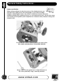
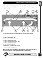
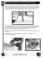
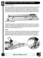
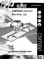
User Manual
CMT650 Kitchen
Worktop Jig
Part no:200650
w w w. a x m i n s t e r. c o . u k
CMT650
www.cmtuk.com
Index of Contents...
Page No.
Index of Contents...................................................................................................................02
What’s in the Box………….………........……..…………..........................................................03
What else you will need....................................................................................... 04
General Safety Instructions............................................................................... 05.06
CMT worktop jig configuration.............................................................................. 07
General guidelines for cutting Worktop joints...................................................... 08
Cutting 90 degree worktop joints................................................................ 09,10,11
Cutting out of square joints.................................................................................... 12
Cutting 45-degree worktop joints......................................................................12,13
Cutting the worktop joint clamp recesses............................................................. 13
Assembling worktop joints......................................................................................14
Other applications for the CMT650 worktop jig................................................14,15
Saf
y Helm
fet
sp irator
Re
Sa
Two
E
R
Ey
fety Viso
Sa
Safety Protection Symbols
et
st Mask
Du
F ootw
ety
r
Def ende
rs
n
ar
s
ve
ro tectio
eP
tiv e Glo
tec
r
ea
n Asse
Ma
bly
m
al
d Manu
ea
Pro
!
The symbols shown on the cover of this
manual advise that you wear the correct
safety protection when using this machine.
SAFETY!!
What’s in the Box...
Model Number:
CMT650
1 No.
A
CMT 650 Phenolic plastic worktop jig
3 No.
B
Positioning stops fitted with rubber O-rings (2 rings per stop)
1 No.
C
Phenolic length stop finger
1 No.
D
M6 Butterfly Screw
1 No.
E
M6 Caphead bolt
2 No.
F
M6 washer
1 No.
Instruction Manual
A
B
D
C
F
PHONE 0845 6040064
E
03
What else you will need...
A
Heavy duty router with 12.7mm (1/2") collet
B
30mm guide bush
C
Collet spanner and guide bush fixing screws
D
Pair of clamps (ideally long reach with soft facings or pads
to protect face of worktop)
E
12.7mm x 50mm (40mm for thinner worktops) router cutter
(either CMT 812628 2 flute cutter or CMT 652-628 replaceable
tip cutter).
F
Ear protectors and safety goggles or visor
A
F
B
C
D
04
E
www.cmtuk.com
General Safety Instructions...
Good Working Practices/Safety
The following suggestions will enable you to observe good working
practices, keep yourself and fellow workers safe and maintain your
tools and equipment in good working order.
!
WARNING!!
KEEP TOOLS AND EQUIPMENT OUT
OF THE REACH OF YOUNG CHILDREN
Safety Guide Lines
1.
Ensure that you are conversant with using the router before attempting to use this
Jig.
2.
Always follow the router manufacturers guidelines and safety procedures.
3.
If you have not used a worktop jig previously, make a series of trial cuts in scrap
pieces of worktop to gain experience of the procedure, sequence and cutting
characteristics of both the material, router and jig.
4.
Always wear protective goggles and earmuffs when routing.
5.
Always wear a dust mask or respirator and use dust extraction equipment
whenever possible.
6.
Avoid wearing loose clothing and keep long hair tied back.
7.
Always remove spanners/keys from the router and do not leave them loose on the
work surface or jig while routing.
8.
Always switch off and wait until the router cutter has stopped rotating before lifting
the router from the face of the work.
9.
Always clamp the worktop to a secure rigid surface while cutting.
10.
Whenever possible always cut the worktop joints before cutting the tops to length.
PHONE 0845 6040064
05
General Safety Instructions...
Cutters and Collets
When cutting worktops the abrasive nature of the chipboard core and
laminate faces rapidly wears the cutting edges of any cutter including
tungsten carbide tipped cutters. Any cutter is unlikely to cut more than three
complete worktop joints perfectly cleanly (i.e. male and female parts). Ensure that cutters
are cleaned and sharpened (hand sharpened on a diamond stone) between cutting each
complete joint.
Ensure that the cutter is correctly held in the router collet
(see router manufacturers instruction manual).
Always check that the guide bush is fitted concentric to
the cutter, preferably using a centering mandrel.
06
www.cmtuk.com
CMT worktop jig configuration...
For precise positioning on the worktop, the CMT worktop jig is fitted with three steel stops
fitted into specific holes in the jig to suit each operation. Each stop is fitted with two
neoprene o-rings to hold it securely into the hole. If the stop is difficult to fit, apply a drop of
soap to the o-rings. Ensure that the stops are pushed fully into the holes flush to the
underside of the jig.
F
C
H
G
I
E
B
D
E
D
C
A
The holes for the steel stops are indicated by letters for each specific operation
A. 2 holes - outer part of 45° joint
B. 2 holes - outer part of 90° joint
C. 4 holes - inner part of 90° and 45° joints
D. 4 holes - fixing holes for clamps
E. 3 holes - radius finishing of corners (r8,2)
F. 2 holes - 45° finishing of corners
G. 1 hole - inner part of 45° joint
H. Stop holes to sail standard width worktops
I. Slots for sliding stop fixing screw
NOTE: The CMT jig must be used with a 30mm guide bush and a 12.7mm cutter fitted to
the router. This allows for a cutter offset from the edge of the jig of 9 mm.
PHONE 0845 6040064
07
General guidelines for cutting Worktop joints...
Always ensure that you are cutting from the correct face and into the postform (rounded )
edge of the worktop. When cutting, the direction of rotation of the cutter (i.e. clockwise) will
cut cleanly into the left hand side of the cut, but will tear the face off of the right hand side.
Therefore the waste portion of the worktop must always be on the right hand side.
When cutting worktops to length etc, use a jigsaw to cut away much of the waste to within
3mm of the required cut line and then trim the cut edge with the router guided against the
edge of the jig. This will leave a straight square edge to align the jig stops against.
Remember always cut into the post-form edge, never out of it.
Always fit soft packing under the clamp heads when clamping against the laminate face of
the worktop.
When possible always leave the worktop over-length to allow the joint to be re-cut if
incorrectly cut the first time.
08
www.cmtuk.com
Cutting 90 degree worktop joints...
Radius or 45˚corners
Right Hand Joint
Left Hand Joint
Peninsula
M
M
F
F
M
F
F
M
Rear edge of worktop
against wall
M: Male section
F: Female section
!
PLEASE NOTE
When cutting a 90-degree joint to the right hand end of the worktop, have the
worktop (decorative laminate) face up. For the abutting male section turn the
worktop face down.
When cutting a 90-degree joint to the left hand end of the worktop, have the
worktop (decorative laminate) face down. For the abutting male section turn the
worktop face up.
Setting the width:
The first step is to set the jig to suit the width of the worktop. If it is a standard width of
worktop, then stop positions H can be used. If there is any discrepancy in the exact width
or if the worktop is wider or narrower than this then the sliding width stop must be used.
Stop positions H
PHONE 0845 6040064
09
Cutting 90 degree worktop joints continued...
Using the sliding stop:
Always use a stop peg to set the jig to the correct worktop width wherever possible. But for
Non standard worktops or where a top has been cut to a none standed width; position the
sliding stop, fitting it to the underside of the jig with the clamping screw, secured by the
clamping knob and washer, through the respective slot. (dependant on worktop width) Fit
two stop pegs in holes B, hold these tight to the front face of he worktop, checking that the
jig is square to it. Adjust the sliding stop up to the rear edge and tighten the clamp screw.
Cutting the female edge:
Position the stops in holes C on the jig (See Page 07). There is one stop that sits against
the end of the worktop and two along the front face. The front stops are set in two of the
four holes, the width of the worktop determining the distance apart. Ensure that all stops are
tight against the worktop edges before clamping the jig to the worktop. Ensure that the
clamps do not infringe the path of the router.
Cutting:
Make the cut in a series of shallow passes, the finer the cut the less effort being placed on
the cutter and the easier it will be to control the router. Keep the feed speed constant and
ensure that the router remains level on the face of the jig. Always work from left to right,
keeping the guide bush against the edge. To finish, press the guide bush a little harder
against the cut edge of the worktop and make a final fine pass across the full edge depth.
10
www.cmtuk.com
Cutting 90 degree worktop joints continued...
Cutting the male section:
First turn and check that the worktop is the correct way up.
When cutting the male edge, leave the sliding width stop or stop H in position and fit two
stops in the holes B.
Position and clamp the jig across the end of the worktop, ensuring that it is square to the
front edge and that the stops are tight against the end. Support the waste end of the
worktop to the jig using a clamp or by supporting it on a sacrificial work-surface below
(to prevent it dropping and tearing the laminate at the end of the pass).
Cut the joint face following the same routing procedure as for the female cut.
Compensating for out of square walls:
Slight variations can be accommodated with worktop jigs, but only up to approximately
3 degrees either way. However these joints will never be as precise as a true 90-degree
worktop joint. The angle is always cut on the male section of worktop.
Where possible place the worktops in position with the male section over the female. If
space does not allow this, use a bevel gauge or other method to take off the angle and
transfer it to the worktop. Remember which end you are cutting and turn them face up or
down as necessary. Mark the inner edge of the female section on the underside of the male
section. This line will be the cut line for the angled male section. Turn the male section over
and mark the angled line clearly. From this line draw a line parallel to it and 9mm from it
(to allow for the guide bush margin).
See Fig 1: Fit the two stops into holes B on the jig and, with the sliding stop loose, position
the jig over the worktop with the two stops against the front edge so that it is square. Check
that the stops are tight against the front edge and clamp the jig to the
worktop. Draw a
line 8.5mm parallel to the edge of the jig. Position the pointed end of the sliding length stop
against the end of this line and tighten the clamping screw.
See Fig 2: Unclamp and remove the two front stops. Lay the jig on the cut line with the
point of the sliding stop on the rear end of the angled cut line. Pivot the jig around this point
until the guide edge is parallel to the angled cut line, but 8.5mm away from it. Clamp the jig
securely to the worktop and cut the male joint following the routing procedure as before.
PHONE 0845 6040064
11
Cutting out of square joints...
Fig 1
B
Fig 2
B
Sliding stop
Cutting line
Sliding stop
Cutting 45-degree worktop joints...
To cut 45-degree corner joints on worktops, use the 22.5 mm angled end of the CMT
650 jig.
As with 90-degree worktop joints, for 45-degree joints the worktop must be cut with
the correct face upwards depending on whether it is a right or left-hand end or
female or male joint edge.
The first step when cutting 45-degree joints is to carefully set out and cut the 45-degree
angle on the relative end of the worktop (leave the worktop over length if possible to allow
joint to be re-cut if incorrect). When cutting worktops to length etc, use a jigsaw to cut away
much of the waste to within 3mm of the required cut line and then trim the cut edge with the
router guided against the edge of the jig or a straight edge. This will leave a straight square
edge to align the jig stops against.
Cutting the female edge (See Fig 3):
Insert two stops into holes C and one into hole G. Position the jig on the worktop with the G
stop against the front edge and the C stops against the angled cut edge. Make the cut with
the router following the same procedure as for 90-degree joints.
Cutting the male edge (See Fig 4):
Insert the stops into holes A, hold them tight against the front edge of the worktop and
clamp the jig firmly. Make the cut with the router following the same procedure as for
90-degree joints.
12
www.cmtuk.com
Cutting 45-degree worktop joints...
Fig 3
G
C
C
Fig 4
A
A
Cutting the worktop joint clamp recesses...
To cut the clamp recesses, fit two stops in the jig holes D. The positioning of the clamps
should be no less than 100mm in from the front edge of the worktop. However the spacing
between them can be as on the jig or altered to suit the worktop width. Remember to match
them on both adjoining sections of worktop, setting-off from the front edge by measuring or
transfer batten.
Butt the stops against the joint edge and clamp it firmly. Cut the recesses to a depth so that
the clamp bolt is approximately centred on the thickness of the worktop. The same 30mm
guide bush and 12.7mm cutter is used for this operation, cutting in a series of shallow
passes and taking out all of the waste from the recess.
PHONE 0845 6040064
13
Assembling worktop joints...
When assembling worktop joints it is advisable to insert biscuit dowels (size No 20) to assist
in aligning the worktop surfaces and prevent movement between the faces. Recesses for
the biscuits can be cut with the router or a biscuit jointer between the clamp recesses
inserting no less than 4 dowels along a 600mm width of worktop.
For biscuit jointer with a router use a 4mm x 47.6mmm arbor mounted slot cutter guided
with a 22mm bearing to produce the slot for the biscuit. [Order no for biscuit joint cutter,
arbor and bearing 310127 (1/2” shank) or 310126 (1/4” shank)].
The two cut chipboard faces of the joint must be sealed on assembly to prevent the ingress
of water. This can be done using a fully waterproof adhesive or better, a coloured worktop
sealant/adhesive. The latter are available in a range of colours that can be mixed and
matched to blend with the colour of the worktop laminate. On cheaper worktops it may be
found that the chipboard core spreads or breaks-out slightly on cutting. This will need to be
trimmed back lightly with abrasive paper before assembly. Take care not to touch the
laminate edge when doing this.
Other applications for the CMT650 worktop jig...
Radius corners and 45-degree corners:
To cut radius corners on worktops and peninsular units, insert three stops into holes E and
make the cut with the router in a series of shallow passes as previously described.
E
E
14
E
www.cmtuk.com
Other applications for the CMT650 worktop jig...
To cut 45-degree corners on worktops and peninsular units, insert two stops into holes F
and make the cut with the router in a series of shallow passes as previously described.
F
F
PHONE 0845 6040064
15
Part no.200650
CMT650
CMT UK Unit 10 Weycroft Avenue
Axminster Devon EX13 5PH
PHONE 0845 6040064
Distributed by Jet Tools & Machinery Ltd
www.cmtuk.com