1
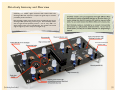
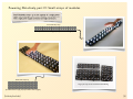
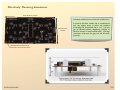
Interactive LED Modules
An open-source hardware+software project. For design files, source code, &
additional documentation, please visit: http://wiki.evilmadscience.com/Octolively
Support: http://www.evilmadscientist.com/forum/
Evil Mad Science LLC
http://evilmadscience.com/
For assembled & kit versions
User Manual v. 1.0b
Octolively Anatomy and Over view
Octolively is a tileable, digital interactive LED module filled with
ultrabright LEDs that respond in complex and gentle ways to stimulus
provided by human interaction.
Each Octolively module is 4 X 8 inches in size, and features eight 10 mm
ultrabright LEDs, spaced along a two-inch grid. Each Octolively module
also has eight infrared proximity sensors— one for every LED —to
detect nearby motion, even in total darkness. The modules can be tiled
edge-to-edge, in any size or shape of rectangular array.
Microcontroller
Visible LEDs (8), 10 mm ultrabright
Octolively modules come pre-programmed with eight different effects
that respond to motion and gradually fade back to idle when there is no
motion, making them ideal for interactive LED walls, bar tops, and coffee
tables. You can switch between the different effects with a button press.
Each Octolively module is controlled by an on-board microcontroller
and functions as a self-contained, stand-alone device. You do need to
provide power (5 V DC), but no central computer nor programming is
required.
Power switch (bottom side)
(Soldering kit version only)
Power jack (bottom side)
Edge connectors (M)
Screw terminal location
(bottom side)
Programming header
Mounting standoffs (4)
Edge connectors (F)
Mode select
button
Proximity sensor clusters (8):
•Infrared phototransistor (black lens)
•Infrared LED (blue lens)
[Octolively User Guide]
[2]
Planning your installation: Powering Octolively, part I
Octolively modules require regulated 5V DC power to operate.
It is important to understand these power requirements, and to
understand your options for providing that power before
beginning assembly.
Octolively Power Supply Requirements
1. The power supply should have regulated 5V DC output.
Regulated power supplies keep their output within a few
percent of 5 V DC.
(Unregulated 5 V power supplies may have voltage
well in excess of 5 V, often approaching 10 V.)
2. The power supply must have current capacity of at least
200 mA (i.e., 0.2 A) per module that it powers.
For example, a single 5 V DC, 1 A power supply can
power up to five Octolively modules.
Extra current capacity is not a problem; you can power
1, 2, 3, 4, or 5 modules from one 5 V DC, 1 A power supply.
3. Each module should be connected to
only one power supply at a time.
If you connect two different power supplies to one module
at the same time, you are effectively connecting those
two power supplies in parallel.
(That’s usually a “no-no.” Do so only when explicitly
recommended by your power supply manufacturer.)
[Octolively User Guide]
[3]
Powering Octolively, part II
Now that we’ve gone over the electrical requirements, how
do you physically connect Octolively to your power supply?
Ways to connect Octolively to your power supply
1. Power jack (2.5 x 5.5 mm, center positive)
Octolively kits are supplied with a high-current 2.5x5.5 mm
barrel jack, that mounts on the bottom side of the circuit
board. This can be used to connect directly to a suitable power
supply: 5 V DC, regulated, Center positive 2.5 mm plug.
2. Edge connectors
Octolively modules can connect to each other side-to-side
and/or top-to-bottom through their edge connectors.
For small arrays (or small sections of large arrays),
these edge connectors can be used to share power
between neighboring boards.
3. Screw terminals
Octolively modules feature a location for an optional twoposition screw terminal that can be mounted to the bottom
(or, if you prefer, the top) of the circuit board. If installed, 5 V
power can be connected to the modules through these
screw terminals.
4. Hardwired power connections
The next few pages discuss the edge connectors
and give recommendations for powering small,
medium and large arrays of modules.
[Octolively User Guide]
If the screw terminal is not installed, wires providing 5 V power
can be soldered directly into the location normally used for the
screw terminals.
[4]
Powering Octolively, part III: Edge Connectors
Unpowered board
(No power supply connection)
Powered board – Now
powered through edge connector!
Powered board – Already connected
to a 5 V DC power supply
Powered board
(Still connected to its power supply!)
1. All modules must be oriented the same way to use
the edge connectors. Do not reverse polarity or
otherwise connect M-M or F-F.
When can you power boards
through the edge connectors?
[Octolively User Guide]
2. The edge connectors and power jacks are rated
for 4 A maximum. Even if your power supply is
huge, you can only power a maximum group of
20 panels through one power supply connection.
[5]
Powering Octolively, part IV: Small arrays of modules
Small Octolively arrays– up to the capacity of a single power
supply and consisting of 20 or fewer modules –can be powered
with a single power supply connection and edge connectors.
4-inch wide strip array
(5 modules: Power supply capacity needed: 1 A or higher.)
8-inch wide strip array
Larger-yet arrays can be constructed with 2D tiling
(9 modules: Power supply capacity needed: 1.8 A or higher.)
[Octolively User Guide]
[6]
Powering Octolively, part V: Mid-size arrays of modules
For Octolively arrays too large to be powered from a single power
supply, you can selectively disable the edge connectors, splitting it
into independent small arrays.
Alternately, you may wish to follow the “Large array” methods from
the next step (Introduction VII), entirely bypassing power from the
edge connectors.
X
X
X
X
X
X
X
X
X
X
Example: This array of 30 Octolively modules is powered by three 5 V
DC, 2 A plug-in power supplies. Each power supply drives 10 modules.
The modules are all connected together through their edge
connectors, except where the connections have been disabled– the
locations marked by with an “X.” (Later, we’ll show you how to disable
those edge connectors.)
[Octolively User Guide]
[7]
Powering Octolively, part VI: Large arrays of modules
For large arrays and permanent installation, it may be preferable to
run individual power wires to each module, attached either with
screw terminals or directly soldered (hardwired) into place.
In this case, the edge connectors should normally be disabled, so
that each module is only connected to power from a single source.
While the wiring in this case can become voluminous, it can be more
straightforward, as an arbitrarily large array of Octolively modules
can be powered, given a large enough 5 V power supply.
[Octolively User Guide]
[8]
Powering Octolively, part VII: Power switches
The soldering kit version of Octolively features a high-power slider
switch, which can be used to switch on or off up to 20 modules
connected together through edge connectors.
For installations of ready-to-use Octolively modules, or for any
installation larger than 20 modules, you will need to provide a means
of switching power on and off if one is desired.
It is possible, for example, to use a mechanical switch or relay to
switch on and off the 5 V DC between a power supply and the
modules.
However, it is generally preferable to switch the power supply on
and off from the AC side. For small-scale installations this can be
done with a simple power strip or light switch that controls a power
outlet. For a safe relay-based solution, we recommend the use of
the Power Switch Tail. For larger installations, you may need to
consult with a professional electrician.
[Octolively User Guide]
[9]
Disabling edge connectors, part I
Edge connector “J1”
Power can be normally be transmitted through any of
the edge connectors. If it is necessary to disconnect
power between two neighboring modules, you can do
so by clipping the power “jumpers” near edge
connectors connectors J1 and/or J4.
Clipping the two jumpers near J1 will prevent power
from being transmitted through edge connector J1,
and clipping the two jumpers near J4 will prevent
power from being transmitted through edge
connector J4.
First, locate edge connectors J1 and J4.
Edge connector “J4”
[Octolively User Guide]
[10]
Disabling edge connectors, part II
On Octolively soldering kits, the two jumpers
(in locations JP1, JP2 or JP3, JP4) may be filled
with either a loop of wire or a “zerohm”
jumper, which looks like a resistor with one
black stripe.
In either case, clip the wire (e.g., with a pair of
wire clippers) on both jumpers to disconnect
power from the edge connector.
On pre-assembled Octolively modules, the two jumpers by the edge
connectors are horizontal “zerohm” jumpers, which looks like
resistors with one black stripe.
Clip the wire (e.g., with a pair of wire clippers) on both jumpers to
disconnect power from the edge connector. Clip the wire at both
sides to completely remove the body of the zerohm jumper.
[Octolively User Guide]
[11]
Optional screw terminals / hardwiring point
Location J7 on the bottom side of the circuit board is
for an optional 2-position screw terminal for
connecting 5 V power (+ 5V DC/GND) to Octolively.
If not installing the screw terminal, J7 can be
used as a port for hardwiring your power
connections (+5 V DC /GND) to Octolively.
[Octolively User Guide]
[12]
Octolively: Mounting hardware
Octolively modules are supplied with 6-32 x
3/4” aluminum standoffs and 6-32 by 1/4”
stainless steel button socket cap head screws.
Mount the standoffs at each corner of Octolively.
You can tighten the screws with a 5/64” (2 mm) hex wrench.
If you do not have one, drop the screw through one of the
holes, put your finger over the screw to hold it still, and thread
the standoff fully onto it. (If you press firmly on the screw head
while doing so, you can get the standoff very tight this way.)
[Octolively User Guide]
[13]
Octolively: Mounting dimensions
8 inch (20.32 cm), nominal
Octolively modules have a nominal size of 4x8 inches.
4 inch (10.16 cm),
nominal
In practice, the exact module size, as manufactured,
may vary slightly above or below this standard.
Accordingly, we recommend that a 1/16” (1.6 mm)
gap be allowed between neighboring modules to
allow for variation in actual module width. (The edge
connectors easily span this gap, and will still work
properly.)
Mounting holes: 6-32 clearance (4),
located 1/4” X 1/4” from each corner
3/4”
3/4”
The circuit board is 1/16” (1.6 mm) thick. Always allow at least
3/4” (19 mm) clearance above and below the circuit board.
[Octolively User Guide]
[14]
Octolively: Options and Settings
There are 8 standard response functions.
To advance to the next response function, press the
button once. When you do so, the “next” LED in
sequence will light up for about two seconds (to
indicate which program), and then the board will go
begin working with the new response function.
0. Gentle fade
1. Slow fade
2. Quick fade
3. Ripple
4. Sparkle
5. “Heating” with fade
6. Shadow mode
7. Trigger and very slow fade
Octolively has a single control button.
(Program 0 is indicated by LED D0, and so on.)
Try them all out, and see which you like best!
There are four built-in levels of sensitivity.
To change the sensitivity level, hold the button for about
ten seconds until it enters a different mode, where 1, 2, 3,
or 4 pairs of LEDs are lit. While in this “sensitivity
adjustment” mode, press the button to switch between
the four sensitivity levels.
Higher sensitivity increases the effective sensing range, but
can also lead to more jittery behavior and “false positive”
motion detection.
[Octolively User Guide]
Lowest sensitivity
Low sensitivity
High sensitivity
Highest sensitivity
[15]
Interactive LED Modules
evilmadscience.com
[16]