1
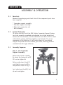
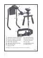
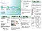
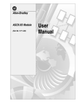
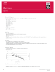
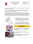
Advanced Camcorder Support System
Instruction Manual
PAG ORBITOR
Advanced Camcorder Support System
Instruction Manual
CONTENTS
SECTION
PAGE
1
SAFETY
2
2
ASSEMBLY & OPERATION
3
3
PARTS AND ASSEMBLIES
9
4
ACCESSORIES
11
5
WARRANTY
12
1
SECTION 1
SAFETY
1.1
This booklet contains important safety and operating instructions.
Please read these fully before using the PAG Orbitor and any of its
component parts.
ATTENTION:
THE TELESCOPIC SUSPENSION ROD CONTAINS POWERFUL SPRINGS AND
IS POTENTIALLY DANGEROUS. OPERATE ONLY IN ACCORDANCE WITH
THESE INSTRUCTIONS.
Keep the telescopic suspension rod out of the reach of children.
Never release the restraining cord unless the rod is in position for
use. Do not release the restraining cord with the rod held loose in
the hands.
Only collapse the suspension rod when it is in position on the PAG
Orbitor. Loop the red restraining cord around the lug on the side of
the rod before removing the Orbitor.
The counterbalance weight must be secured to the back plate of the
shoulder support assembly in accordance with the instructions on Page
7.
2
SECTION 2
ASSEMBLY & OPERATION
2.1
Parts List:
Remove the packaging and check that all the component parts have
been supplied:
*
*
*
*
Camcorder support assembly.
Shoulder support assembly.
Telescopic suspension rod.
Belt assembly.
2.2
System Philosophy:
To obtain the best result the PAG Orbitor Camcorder Support System
has to be correctly assembled and adjusted to suit the weight and
balance of the camcorder, and the individual user. When this has been
achieved the camera will feel weightless and control of its 3-axis
movement will be effortless. It will enable hours of use without
fatigue and provide the most mobile, yet stable, shooting platform
available from this type of device.
2.3
Assembly Sequence:
Step 1 - The Camcorder
Support Assembly
Release the clutch assembly
A, rotate the horizontal rod C
90º and re-tighten A.
B
D
C
A
Release adjustment knob B
and slide the cross bar D to
the position shown in Fig. 1.
Lock adjustment knob B, but
do not overtighten.
Fig. 1
3
E
2
5
C
D
F
A
6
B
6
1
3
4
7
1
2
3
4
5
6
7
Camcorder Support Assembly
Shoulder Support Assembly
Telescopic Suspension Rod
Waist Belt Assembly
Camcorder Mounting Plate
Shoulder Straps
Support Plate
A
B
C
D
E
F
Clutch Assembly
Adjustment knob
Horizontal Rod
Cross Bar
Adjustment knob
Vertical Rod
See Page 9 for ordering replacement parts and assemblies.
Fig. 2
4
Release adjustment knob E on the shoulder support assembly and
insert stepped portion of rod C fully into the shoulder support assembly and lock E (see Fig. 2 opposite).
Step 2 - The Waist Belt Assembly
The waist belt can be adjusted to fit users of all sizes. Place the belt
around your waist, with the support plate positioned at the front.
Note that the belt will carry the weight of the camera and should be
adjusted to fit tightly, but comfortably, without restricting your
normal body movements.
Step 3 - The Telescopic Suspension Rod
Place the telescopic suspension rod into the well on the support
plate. DO NOT RELEASE IT AT THIS STAGE.
Step 4 - Adjusting the Assembly
It is important that the first fitting should be carried out before the
camera is mounted to the PAG Orbitor.
The shoulder assembly incorporates two straps that provide stability
during operation. The straps must be adjusted to fit the individual
user, but must not be too tight.
1. Bring the right-hand shoulder strap forward over the assembly. Lift
the Orbitor onto your right shoulder, and leave the left-hand shoulder
strap hanging down your back.
2. Connect the telescopic suspension rod to the rubber coupling-pin
located between the handles on the underside of the camcorder
support assembly.
3. The PAG Orbitor is now in position, supported between your shoulder and your waist. Using both hands you can now adjust each strap
to the required length.
4. Left-hand strap.
Reach behind your back with your left hand and bring the strap
forward. Plug it into the left-hand socket on the support pad of the
waist belt and adjust the length with light tension. This strap prevents the shoulder pad assembly from slipping off your shoulder.
5
5. Right-hand strap
Pull the right-hand strap over your chest and plug it into the righthand socket on the support pad and adjust the length with light
tension. The function of this strap is to prevent the assembly slipping
backwards.
Step 5- Familiarisation
It is advisable to familiarise yourself with the fluid mobility of the
PAG Orbitor before fitting the camcorder. This sequence should always
be followed in use as well as practice:
Release the locking tension of the vertical rod F (see Fig. 2 on Page 4),
followed by clutch assembly A, and finally, holding a degree of back
tension against the telescopic suspension rod, carefully release its
restraining loop.
When you are familiar with the fluid motion of the camcorder support
assembly, and the adjustment of tensions required for panning, tilting
and rolling, you can remove the assembly (Step 6) before mounting
the camera (Step 7).
Step 6 - Removing the PAG Orbitor
This sequence should always be followed, as it allows a free hand to
support the camera, when mounted:
1. Press down and secure the suspension rod with the restraining
loop.
2. Centre the panning assembly and lock the adjustment knob.
3. Adjust and lock the tilt clutch assembly approximately 90º to the
horizontal rod.
4. Release the left-hand shoulder strap followed by the right.
5. Carefully lift the camcorder support assembly off the suspension
rod and place on the floor or table.
6. Remove the suspension rod from the waist belt.
6
Step 7 - Mounting the Camcorder
The professional camera mounting system is fully adjustable and
universal.
1. First, remove the sliding camcorder plate by releasing the small
lever.
2. Slide the plate up to the safety lock, then press the safety button
to continue to remove the plate.
3. Choose the appropriate camcorder screw or screws to suit the bush
or bushes on the underside of the camcorder. Extra screws may be
provided for this. To remove the unwanted screws from the sliding
plate push the captive rubber bung, or retaining spring, clear of the
hole at the end of the slot. The screws can be slid up to the hole and
removed. Remember to reposition the bung. NOTE: some camcorders
have a location hole to prevent the rotation of the mounting plate.
The sliding plate incorporates a brass spring-loaded pin that should be
aligned with the hole in this instance. Secure the plate to the bottom
of the camcorder using a coin to tighten the screws.
A USEFUL TIP:
Always consider the centre of gravity of the camcorder when mounted
to the plate. Before sliding it into the camcorder support assembly,
place a pencil at an angle of 90º beneath the sliding plate under the
camcorder, and move the camcorder up and down until you find the
centre of gravity. Note the position, and endeavour to align this point
just behind the centre line of the handles when sliding the camcorder
onto the mounting block, and locking it in position.
Step 8 - Final Adjustments
Once the camcorder has been mounted you can return the camcorder
support assembly to your shoulder. Fine adjustments can then be made
to the camcorder’s point of balance, i.e. if the camcorder tends to tip
forward, release the lock and slide it back until it stabilises. Sideways
instability can be eliminated by adjusting the position of the block
below the camcorder mount on clutch rod D. (see Fig. 2 on Page 4).
Ensure that the well for the suspension rod is central to your body and
the camcorder support assembly. You are then ready to experience the
full benefits of the PAG Orbitor Camcorder Support System.
7
2.4
The Counterbalance Weight
The PAG Orbitor is supplied with a counterbalance weight (1.25kg),
fitted to the back plate of the shoulder pad assembly. The weight is
held in position by a single screw and securing knob.
ALWAYS ENSURE THAT THE WEIGHT HAS BEEN SECURED TO THE BACK
PLATE WITH THE SECURING KNOB AND CANNOT FALL FROM THE BACK
PLATE.
The webbing strap which is included for the purpose of securing a
battery to the back plate, in place of the weight, can be left in
position, as extra security.
2.5
8
Service
If a fault develops please return the product to your dealer or to
PAG Ltd. 565 Kingston Road, Raynes Park, London SW20 8SA, UK.
Tel +44 (0) 20 8543 3131 Fax +44 (0) 20 8540 4797
E-mail [email protected].
SECTION 3
PARTS AND ASSEMBLIES
3.1
The following parts and assemblies are available from PAG Ltd.
or your nearest PAG Dealer (in the UK), and your nearest PAG Agent
(outside the UK).
3.2
Parts:
Y0191
M4330
Y0180
R3822
Y0190
Y0058
Y0110
Y0051
Y0170L
3.3
Camcorder Mounting Plate
Adjustment Knob
Shoulder Strap
Weight Fixing Screw
Weight Securing Strap
Counterbalance Weight
Rubber Support Coupling
Clutch Knob
Waist Strap (size XL)
Assemblies:
Y1005
Handle Assembly
Y1001
Telescopic Suspension Rod
Y1002
Shoulder Support Assembly
Y1003
Belt Assembly
Please refer to Fig. 3 on Page 10.
9
Y0191 Camcorder Mounting Plate (does not include mounting block)
Fig. 3
M4330 Adjustment Knob
M4330
Adjustment
Knob
Y1002 Shoulder
Support Assembly
Y0051 Clutch Knob
M4330 Adjustment Knob
M4330 Adjustment Knob
Y0110 Support Coupling
Y1005 Handle Assembly
Y1001
Suspension
Rod
M4330 Adjustment Knob
R3822 Weight Fixing Screw
Y0190 Weight Securing Strap
Y0058 Counterbalance Weight
Y1003 Belt Assembly
Y0180 Shoulder Strap
Y0170L Waist Strap (size XL)
Parts:
Y0191
M4330
Y0180
R3822
Y0190
Y0058
Y0110
Y0051
Y0170L
10
Camcorder Mounting Plate
Adjustment Knob
Shoulder Strap
Weight Fixing Screw
Weight Securing Strap
Counterbalance Weight
Rubber Support Coupling
Clutch Knob
Waist Strap (size XL)
Assemblies:
Y1005 Handle Assembly
Y1001 Telescopic Suspension Rod
Y1002 Shoulder Support Assembly
Y1003 Belt Assembly
SECTION 4
ACCESSORIES
4.1
The appropriate PAG battery will make the perfect counterbalance,
in place of the weight supplied with the PAG Orbitor. The back
plate of the shoulder pad assembly can be fitted with the PAGlok
Connector professional battery mount. This will enable a 12V to
14.8V PAGlok battery to be used as a means of powering a Paglight
M 12V on-board camera light. The camcorder can also be powered
from this battery with the appropriate PAG DC Adaptor.
4.2
The PAG C6 PowerPack, a 6V battery supplied as part of the
Paglight C6 Lighting Kit, Model 1001, also makes a good
counterbalance and replacement for the weight supplied as part of
the PAG Orbitor. This all-inclusive, miniature on-board camera
lighting kit is an excellent product and one that will greatly
enhance your system.
If you are based in the UK contact your nearest PAG dealer or the
PAG Sales Department for details of PAG products. If you are based
outside the UK contact your nearest PAG Agent (visit the PAG
website www.paguk.com for details of your nearest PAG Agent).
4.3
Remote controls, LCD monitors and other professional camera
accessories can be clamped to the lightweight but strong structure.
11
SECTION 5
WARRANTY
5.1
Notwithstanding any provision of any agreement the following
Warranty is exclusive: PAG Limited warrants each PAG Orbitor it
manufactures to be free of defects in material and workmanship
under use and service for 1 year from the date of purchase. This
warranty extends only to the original purchaser. This warranty
shall not apply to fuses or any product or parts which have been
subject to misuse, neglect, accident or abnormal conditions of
operation.
5.2
In the event of failure of a product covered by this warranty,
PAG Limited will repair and calibrate equipment returned to an
authorised Service Facility within the period of the warranty,
provided the warrantor's examination discloses to its satisfaction
the product was defective. The warrantor may, at its option,
replace the product in lieu of repair. With regard to any equipment
returned within this period, said repairs or replacements will be
made without charge. If the failure has been caused by misuse,
neglect, accident or abnormal conditions of operation, repairs will
be billed at a nominal cost. In such a case, an estimate will be
submitted before work is started, if requested.
5.3
The foregoing Warranty is in lieu of all other warranties, express or
implied, including but not limited to any implied warranty or
merchantability, fitness or adequacy for any particular purpose or
use. PAG Limited shall not be liable for any special, incidental, or
consequentialdamages, whether in contract, tort, or otherwise.
12
U5078 ISS C / JUNE 2009
PAG Ltd. (UK)
565 Kingston Road,
Raynes Park,
London SW20 8SA
T +44 (0) 20 8543 3131
F +44 (0) 20 8540 4116
E [email protected]
www.paguk.com
PAG USA
10663 Burbank Blvd,
North Hollywood,
CA 91601, USA
T 818 760 8265
F 818 760 8805
E [email protected]
www.pagusa.com