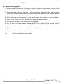
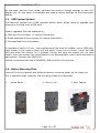
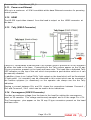
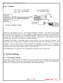
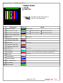
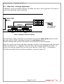
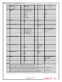
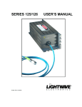
1
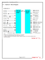
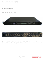
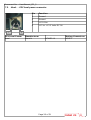
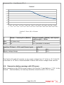
Document No. : UserManual_CII_2
VOLAMP
User Manual
Page 1 of 31
Document No. : UserManual_CII_2
Important
Powering up the Camlinx II
The CamlinxII system takes up to 60 seconds to power up.
During this time, video and audio passed by the system is unreliable and should be
ignored.
Disclaimer
All information contained in this manual is believed to be accurate and reliable.
However, Volamp Ltd assumes no responsibility for its use. Since conditions of product
use are outside our control, we make no warranties express or implied in relation
thereto. We therefore cannot accept any liability in connection with any use of this
information.
This product is not intended for use in life support appliances, devices or systems where
a malfunction of the product can reasonably be expected to result in personal injury.
Use of any Volamp product in such applications is expressly prohibited.
Whilst every effort has been made to ensure that this document is correct, errors can
occur. If you find any errors or omissions please let us know, so that we can put them
right
Laser Safety
Invisible laser radiation. Class 1 lasers are used in this product for fibre optic
communications. The wavelength used is in the infra-red band so the light emitted
cannot be seen. Although the levels are low and are classified as safe under all
conditions of normal use, we recommend that users avoid looking directly into the
beam.
Trademarks
Camlinx II is a trade mark of Volamp Limited.
Opticalcon ® is a registered mark of Neutrik AG
Page 2 of 31
Document No. : UserManual_CII_2
Table of Contents
Important..........................................................................................................2
Powering up the Camlinx II...............................................................................2
Disclaimer .....................................................................................................2
Laser Safety...................................................................................................2
Trademarks....................................................................................................2
1.Introduction...................................................................................................5
1.1.Camlinx II : Block Diagram.........................................................................6
2.Camlinx II Units..............................................................................................7
2.1.Camlinx II : Base Unit...............................................................................7
2.2.Camlinx II : Head Unit...............................................................................8
2.3.Dimensions and Weights............................................................................9
3.Camlinx II Configurations...............................................................................10
4.Quick start guide...........................................................................................11
5.Camlinx II Features.......................................................................................12
5.1.Video ....................................................................................................12
5.2.Programme Audio ...................................................................................12
5.3.Displays.................................................................................................12
5.4.Thumb wheel Switches.............................................................................12
5.5.USB System Updates...............................................................................13
5.6.Battery Mounting Plate.............................................................................13
5.7.Tri-Level / Bi-Level sync...........................................................................14
5.8.Serial Data ............................................................................................14
5.9.Timecode...............................................................................................14
5.10.Ethernet...............................................................................................14
5.11.Power over Ethernet..............................................................................15
5.12.HDMI...................................................................................................15
5.13.Tally (26W D Connector)........................................................................15
5.14.Convergence (26W D Connector).............................................................15
5.15.GPIO (26W D Connector)........................................................................16
5.16.Talkback..............................................................................................17
6.System Settings............................................................................................17
6.1.Screenkeys display..................................................................................17
6.2.Fibre Level bars......................................................................................19
6.3.Base Unit : Settings adjustment................................................................20
6.4.Head Unit : Settings adjustment...............................................................22
7.Connectors...................................................................................................24
7.1.Talkback - 5 way XLR connectors .............................................................24
7.2. Base - Serial 1 & 2 connector pin assignments...........................................24
7.3. Base - 26 Way D-Type Connector pin assignments......................................25
7.4. Head - Serial 1 & 2 connector pin assignments.........................................25
7.5. Head - +12V local power connector..........................................................26
8.Power .........................................................................................................27
8.1.Introduction...........................................................................................27
8.2.Base power indication..............................................................................27
8.3.Hybrid fibre/power cable..........................................................................27
8.4.Camera low battery warnings with 52V power.............................................28
9.Troubleshooting............................................................................................29
9.1.Fibre ....................................................................................................29
9.2.Power....................................................................................................29
Page 3 of 31
Document No. : UserManual_CII_2
10.Accessories.................................................................................................30
11.Ordering information ..................................................................................30
Page 4 of 31
Document No. : UserManual_CII_2
1. Introduction
Camlinx 2 is a camera back system for multiplexing video, audio, talkback and control
signals onto fibre-optic cables for transmission between a camera and a production
facility. This provides the following benefits;
Greatly increased transmission distance over copper based cable
increased bandwidth / data rates
reduced cable thickness/bulk
reduced susceptibility to EM interference
Systems can be ordered with support for all common connection systems including
Neutrik and Lemo.
Unlike other camera back systems, cameras
can be powered directly from the
Camlinx2 head unit without the need for additional hardware or modules.
The Camlinx2 head unit can be powered from the cable (hybrid cable required) or it can
be powered from a local 12Vdc supply at the head.
A Camlinx 2™ system comprises of a Base unit which resides in the production area
and a camera-mounted Head unit. The two units are connected by a fibre optic cable
containing two fibres.
Power is supplied to the head via a hybrid fibre cable
(incorporates copper conductors as well as the fibres), battery or a local 12V DC supply.
The Camlinx2 system has a USB based upgrade facility which allows users to upgrade
their systems in the field from a USB stick . This feature allows the user to incorporate
new features and enhancements quickly and reliably.
Settings on the base and head units can be adjusted using three position switches
mounted on the front of the units. These switches can be moved from left to right and
also have a centre push position. When using these switches the user must press and
hold the switch in the desired position until he sees the setting change on a display.
Both the head and the base have a small 22mm x 22mm colour display which is used to
display system information. This display also incorporates a large push-button which is
used during adjustment of system settings. In addition, the Base unit also has a 2 x 80
character display used to adjust overall system settings.
A basic Camlinx II system has a single bidirectional HD-SDI channel. Two additional
3G/HD/SD video channels can be added to the system at extra cost. With the addition
of two extra video channels, the system can handle a full 3D 3G camera.
There are three models in the Camlinx II range. In addition to the main Camlinx II
system coverd by this manual, there are two other Camlinx II systems for other
applications ;
1.
Camlinx II Lite
2.
Camlinx II Zero
See website for further details.
Page 5 of 31
Document No. : UserManual_CII_2
1.1. Camlinx II : Block Diagram
Page 6 of 31
Document No. : UserManual_CII_2
2. Camlinx II Units
2.1. Camlinx II : Base Unit
The base unit is housed in an industry standard 1U / 19” rack enclosure with a cooling
fan mounted internally on the right hand side.
Page 7 of 31
Document No. : UserManual_CII_2
2.2. Camlinx II : Head Unit
Page 8 of 31
Document No. : UserManual_CII_2
2.3. Dimensions and Weights
BASE
Dimensions Width x Depth x Height (mm)
Weight (kg)
430 x 270 x 40 ( main 1U enclosure )
2.5
485 x 270 x 40
(including front panel mounts and connectors)
HEAD
180 x 135 x 70 (main enclosure)
185 x 160 x 120
(including fibre pod, connectors,
battery plates, tally light)
Page 9 of 31
1
display,
Document No. : UserManual_CII_2
3. Camlinx II Configurations
The standard Camlinx 2 system is designed to use 9 µm single mode fibre and will not
work with multi-mode cable. Single mode fibres permit cable lengths of several
kilometres.
The system can use 'fibre only' cable or hybrid cable. Hybrid cables include power
conductors as well as the fibres. Power losses down hybrid cables reduce the maximum
length of the hybrid cables to less than 300m. See power section 8 for further
information.
The system requires a direct optical connection between base and head. The signal will
not pass through fibre optic switching equipment such as Ethernet hubs, SMPTE video
switches, etc.
Page 10 of 31
Document No. : UserManual_CII_2
4. Quick start guide
1. Make system connections according to chosen system configuration. Ensure serial
and tally cables are connected to the system.
2. Turn on mains power to the base. Ensure power is present at the head and the
base. Note that the head powers up several seconds later than the base to reduce
power inrush loading on initial power on.
3. Check the power level indicator on the base, ensure the system is not overloaded.
4. Check fibre levels using the screenkeys display at head or base.
5. Set camera number using the menus on the base.
6. Set the serial communications standard (RS232 by default). If a remote control
panel is used, check its operation.
7. Set the head audio input levels -0dB by default.
8. Set the headset microphone input level - +18dB level by default.
9. Adjust the headphone volume level.
10.
System should be operational.
Page 11 of 31
Document No. : UserManual_CII_2
5. Camlinx II Features
5.1. Video
The Camlinx II system supports the following video standards;
Video Standard
SMPTE
Supported
Composite NTSC/PAL/SECAM
170M
Yes
SD-SDI 270MBit PAL
259M
Yes
SD-SDI 270MBit NTSC
259M
Yes
HD-SDI 1485MBit 1080
50i, 25p, 60i, 30p, 24p
292M
Yes
HD-SDI 1483MBit 1080
59.9i, 29.9p, 23.9p
292M
Yes
HD-SDI 1485MBit 720 60p
292M
Yes
Dual Link HD-SDI
372M
3G-SDI
424M
Yes with 3G and 3G-3D options
(See ordering info )
Ethernet
10/100Mb/s
HDMI
Base only
5.2. Programme Audio
Audio input and output connectors are mounted on the side of the Camlinx II head unit.
This allows the Camlinx II system to pass audio without additional hardware. Audio
input levels can be adjusted in 6dB increments and also have the ability to supply
'phantom power' to a microphone.
Embedded audio is passed transparently by the Camlinx II system.
5.3. Displays
Both the Head and Base units have small colour displays (referred to as the screenkeys
display) which present system information to the user. There are fields on the head
screenkeys display that are not present on the base display (see table on next page.)
In addition the Base has a 2 x 16 character LCD display.
5.4. Thumb wheel Switches
Settings on the Base and Head units are adjusted using two thumb wheel switches
(SW1,SW2). These have three positions which are to the left, to the right and centre
push. When using these switches the user must press and hold the switch in
the desired position until the LCD or Screenkeys display changes.
Page 12 of 31
Document No. : UserManual_CII_2
On the base, the two front rocker switches are used to change settings on the LCD
display only. On the head, the switches are used to adjust settings on the screenkeys
display.
5.5. USB System Updates
The Camlinx2 system has a USB upgrade facility which allows users to upgrade their
systems in the field from a USB stick.
System upgrades files are available by;
a) USB stick from Volamp or Volamp Distribution
b) Email attachment from Volamp or Volamp Distribution
c) File download from the website.
To upgrade a Camlinx II unit, the programming files must be loaded onto a USB stick.
Apply power to the head or base unit and allow it boot up as normal. Insert the USB
stick and leave the system for 5 minutes. During this time the system will not pass
signals. Once the system has reconfigured it will automatically reboot itself and start to
pass signals. Remove the USB stick.
Volamp recommend the use of SANDISK USB sticks for this purpose.
5.6. Battery Mounting Plate
Camlinx II can be supplied with different battery mounting plates on the head unit.
This is specified when ordering. The following plates are supported;
1.
Anton Bauer
2. Sony V-Lok
Page 13 of 31
3. PAG PagLok
Document No. : UserManual_CII_2
5.7. Tri-Level / Bi-Level sync
This feature allows gen-locking of cameras. A sync signal connected to the sync input
on the base will appear at the sync output on the Camlinx II head for connection to the
camera. Both bi-level (SD) and tri-level (HD) syncs are supported.
5.8. Serial Data
Camlinx II provides three full-duplex serial channels with a maximum data rate of
500KBit/second. All channels can be configured as RS232 or RS422 using the menus
on the base. Please contact Volamp if support for RS485 is required.
Serial channels 1&2 have dedicated connectors on the base and head units, the third
serial channel is located in the 26 way D-type connector.
Note the crossover of the serial signals between the head and the base.
5.9. Timecode
The system passes Time Code (LTC) between the head and the base.
Frequency of operation 960hz – 2.4 kHz.
24,25 or 30 frames of timecode per second with 80 bits per frame.
5.10. Ethernet
10/100 Ethernet can be passed transparently between the head and the base. RJ45
connectors are present on both units for this purpose. This facility can be used for;
Computer networking
Camera control
Pan and tilt control
Internet access.
Page 14 of 31
Document No. : UserManual_CII_2
5.11. Power over Ethernet
48V up to a maximum of 20W is available at the base Ethernet connector for powering
control panels.
5.12. HDMI
The HD-SDI input video channel from the head is output on the HDMI connector at
the base .
5.13. Tally (26W D Connector)
Camlinx II incorporates a bidirectional Tally system used to provide an on-air indication
at either the head or the base. Connections to the Tally system appear on the 26 way
D-type connectors present on the head and base units. The head has a dedicated Tally
LED indication on the top of the unit which incorporates a push-button switch so it can
be manually disabled.
In addition, there is an 'optical Tallly' light output on the head which will be illuminated.
A 'light guide' (OT-CAMLINXII) can be connected to this output which can be mounted in
the camera eyepiece (or elsewhere) so the operator can always see the the Tally
indication.
Passing a current between IN+ and IN- closes the connections between Common1 /
On1 and Common2 / On2 which can be used to drive indications.
5.14. Convergence (26W D Connector)
Provides an analogue voltage from the base to the head for setting the convergence
point on 3D cameras. This voltage continuously sampled and is in the range 0 to +5V.
The Convergence pins appear on the 26 way D-type connectors present on the head
and base units.
Page 15 of 31
Document No. : UserManual_CII_2
5.15. GPIO (26W D Connector)
There are 4 digital GPIO (General Purpose Input Output) pins in each direction across
the fibre link.
Signals onto the GPIO pins must be at TTL levels
Input Low < 0.7V
Input High
>3V up to a maximum of 6V
Maximum switching frequency of 500KHz.
The GPIO pins appear on the 26 way D-type connectors present on the head and base
units.
Page 16 of 31
Document No. : UserManual_CII_2
5.16. Talkback
Camlinx II can support one or two channel talkback systems. The base unit accepts
two five pin XLR connectors, one for channel A and the other Channel B. The Head has
one five pin XLR connector for a standard headset. Audio from both channels can be
received into the headset either as a single channel in each ear or both channels mixed
and into each earpiece (see section on head settings).
A talkback controller is available which plugs directly into the Camlinx II head. This
allows the user to adjust the headphones volume remotely from the head unit. It also
includes a 'push to talk' button which enables the headset microphone. If a Talkback
controller is not used, the sound is continuously enabled and volume control is adjusted
using the three way rocker switch SW1 on the head unit.
The headphones' microphone can be disabled using SW2 on the head unit.
6. System Settings
6.1. Screenkeys display
Screenkeys colour displays are present on both the head and the base units and provide
system information to the user. As the head unit does not have an 16x2 LCD, additional
information is displayed on the head display. See following table.
Page 17 of 31
Document No. : UserManual_CII_2
FIBRE LEVEL
local
remote
1
2
0
3
8
Numbers on the screen refer to
entries in the table below.
4 5 6 7
9
10
Description
Colour
Notes
0
Camera Number
Black
Set at base
1
Fibre Level % - Local
Green
Also :
Fibre unlocked
Fibre level too low
2
Fibre Level % - Remote
Blue
Also :
Fibre unlocked
Fibre level too low
3
Fibre Driver Temperature
Yellow
4
Audio CH1 :
5
6
7
Head only
Phantom Power ON
Orange
Phantom Power OFF
Purple
Head only
Audio CH2 :
Phantom Power ON
Orange
Phantom Power OFF
Purple
Head only
Headphones :
Individual
Cian
Channel 1 in right headphone, channel 2 in left headphone.
Combined
Pink
Channels 1 and 2 mixed and driving both headphones
Head only
Mic Level :
Input Muted
Grey
Input Enabled
Blue
8
Core temperature
Red
9
Call Indicator
Blue
10
Tally Indicator
Green
Page 18 of 31
Document No. : UserManual_CII_2
6.2. Fibre Level bars
At the top of the screenkeys displays are two horizontal bars which give an indication of
fibre light levels. The local level is the received level at the unit on which the display is
mounted (could be head or base). The Remote level is the receiver light level at the unit
at the far end of the fibre.
The fibre level bars should lie between 20 – 90% for correct operation.
If the level falls too low, the bar will change to red in colour and reliable operation
cannot be guaranteed.
In addition, if communications between the head and base are not locked, the bars will
change to grey in colour. (see below)
Fibre level low indication
0
A red indication on the fibre level bars means the level is
too low for reliable operation.
Action :
1. Ensure fibre connectors are correctly inserted.
2 Check and clean fibres.
3. Check for damaged or broken fibres.
4. Ensure correct fibre in use.
Fibre Communication not locked between head and
base.
0
A grey indication on the fibre level bars means the system
is not locked.
Action :
1. Turn the system off and on (cycle the power).
2. Check fibre connections.
3. Contact Volamp or authorised distributor.
Page 19 of 31
Document No. : UserManual_CII_2
6.3. Base Unit : Settings adjustment
In addition to the screenkeys display, the base unit has a 16x2 character LCD which is
used when adjusting system settings.
FIBRE LEVEL
local
remote
MENU
MAIN
16 x 2 character
LCD DISPLAY
SUB
SEL
SW1
SW2
Base : Switches and LCD display
The left switch (SW1) navigates up and down through the main menu options while
the right switch (SW2) navigates through the sub menu options.
System settings and system information are accessed via these switches.
Once the correct sub menu has been selected, the user must press and hold the centre
button on SW2 until (→) appears. The sub menu can then be adjusted with SW2. To
confirm the setting, press and hold the centre button of SW2 until ( →) disappears.
The following table lists the options available using the base LCD.
Page 20 of 31
Document No. : UserManual_CII_2
Main Menu Options
SWITCH 1
option
(NOTE 1)
Sub Menu Options
SWITCH 2
option
(NOTE 2)
1
CAMLINXII
BASE
1
2
3
4
5
6
7
FPGA Head Temp.
FPGA Base Temp.
PCB Issue No.
Unit ID
Software
Firmware
Start Temp
2
AUDIO
1
2
Left
Right
3
COMP CH2 SET
4
STD
5
CAMERA NUMBER
6
TALLY OUTPUT
1
2
3
7
SERIAL RX TX
1
2
3
8
FIBRE
1
2
3
4
5
SELECT - >
option
(NOTE 3)
(NOTE 4)
55^C
56^C
1
0475ae
2660
N/A
40^C
1
2
Line
Mic
1
2
Enabled
Disabled
STD SDI Output
STD CVBS Input 1
STD CVBS Input 2
STD SDI Input
STD CVBS Output
Indicates the standard
of the selected video
stream.
1
2
3
4
5
1
2
3
4
5
Local
LED
Remote
1
2
3
4
LOCK ON
LOCK OFF
STD
INV
CH1
CH2
CH3
1
2
RS232
RS422
Local
3G1
3G2
Remote
INFO
DRIVER (SFP) Temp
Fibre Loading
Status
NOTES
1 Push left or right to scroll up/down the Main Menu options listed below
2 Push left or right to scroll up/down the Sub Menu options.
3 Press and hold the centre button of Thumbwheel2 (right hand side) until the (- >) appears.
Change the setting by pressing Thumbwheel 2 to the right or left.
To confirm the setting, press and hold centre button of Thumbwheel2 until (- >) disappears.
4 These submenu settings display the system information listed below.
Page 21 of 31
Document No. : UserManual_CII_2
6.4. Head Unit : Settings adjustment
The two 3 position rocker switches on the head adjust Audio and Talkback functions.
When using these switches the user must press and hold the switch in the
desired position until the LCD display changes.
The screenkeys display also incorporates a push-button. By pressing down on the
button, the functions of the two three position rocker switches (SW1, SW2) can be
changed between Talkback and Audio functions.
AUDIO Functions (Press and hold down the screenkeys button to adjust)
GAIN IN1
GAIN IN2
Push rocker switch to left or right to increase / decrease gain by 6dB
increments.
Ph+
Push rocker switch forward to enable or disable 36V Phantom Power (used
to power an external microphone). Setting will be reflected on the
screenkeys display.
TALKBACK Functions
VOLUME
Push rocker switch to left or right to increase / decrease volume into the
headset earphones.
Mono
Push rocker switch forward to select separate talkback channels in each
headphone or a mixture of both into each headphone.
MIC LEVEL
Push rocker switch to left or right to increase / decrease gain by 6dB
increments.
Mute
Push rocker switch forward to mute / unmute the microphone.
Page 22 of 31
Document No. : UserManual_CII_2
When making adjustments with SW1 and SW2, two 'function select' boxes are displayed
on the screenkeys display. The box on the left shows the setting on SW1 and the one
on the right shows the setting on SW2
These boxes show the current settings of the Camlinx II head unit. To change the
setting, press and hold the switch until the setting on the display changes. Release the
switch and the display changes back to camera number.
Setting
Function Select Box displays
GAIN IN
5
Ph+
Line level input 0 – 5
Increments of 6dB (0dB to 30dB range)
Phantom Power ON
Phantom Power OFF
VOLUME
Increase / decrease headphone volume
Mono
Both talkback channels mixed to each earphone (Mono)
Individual channels to each earphone
MIC LEVEL
Mute
5
MIC level input 0 – 5
Increments of 6dB (0dB to 30dB range)
Microphone ON
Microphone OFF
Page 23 of 31
(Stereo)
Document No. : UserManual_CII_2
7. Connectors
7.1. Talkback - 5 way XLR connectors
HEAD
BASE
XLR 5 PIN SKT
Pin
XLR 5 PIN PLUG
Pin CHA
CHB
1
Microphone +
1
GND
GND
2
Microphone -
2
IN-LP+
IN-RP+
3
Ground/screen
3
IN-LN-
IN-RN-
4
Headphones R
4
OUT-LN-
OUT-RN-
5
Headphones L
5
OUT-LP+
OUT-RP+
Talkback Connector
Manufacturer
Head
Neutrik
NC5FBH (socket)
NC5MX
Base
Neutrik
NC5MBH (plug)
NC5FX
Talkback Controller
Connector
Manufacturer
Head
Tyco
7.2.
Mating Connector
Mating Connectors
T01-0560-S04
T01-0550-P04
Base - Serial 1 & 2 connector pin assignments.
5 4 3 2 1
9 8 7 6
Function
Pin
1
0V
Function
Pin
6
NC
2
TX+ (RS232 / RS422)
7
TX- (RS422 only)
3
RX+ (RS232 / RS422)
8
RX- (RS422 only)
4
12V ( 200mA max )
9
NC
5
GND
Page 24 of 31
Document No. : UserManual_CII_2
7.3.
Base - 26 Way D-Type Connector pin assignments.
1 2 3 4 5 6 7 8 9
10 11 12 13 14 15 16 17 18
19 20 21 22 23 24 25 26
GPIO
Pin
1 IN1
9 OUT1
12 IN2
11 OUT2
Pin
Front view
Tally
8 input+
1. Ch3 RX-
17 Output Common1
4 Ch3 TX-
13 GND
5 Ch3 TX+
15 GND
7 Output Off1
16 Output Common2
14 GND
6 Output Off2
Convergence
24 Output On2
10 Convergence
Head - Serial 1 & 2 connector pin assignments.
Function
Pin
1
TX+ (RS232 / RS422)
2
TX- (RS422 only)
3
GND
4
RX+ (RS232 / RS422)
5
RX- (RS422 only)
Serial Connector Manufacturer
Head
26 +5V0 out
23 +12V out
19 OUT3
7.4.
2
Power
Pin
3 Ch3 RX+
25 Output On1
21 OUT4
Serial
18 input-
20 IN3
22 IN4
Pin
Tyco
Mating Connectors
T01-0560-S05
Page 25 of 31
T01-0550-P05
Document No. : UserManual_CII_2
7.5.
1
Head - +12V local power connector.
Pin
Function
1
Ground
2
Ground
3
+12V Out
4
+12 to +13.2 Volts DC IN
4
12V Local Power
Manufacturer
Head
Neutrik
Mating Connectors
NC4MD-LX
Page 26 of 31
NC4FX
Document No. : UserManual_CII_2
8. Power
8.1. Introduction
The CamlinxII head and base units can be connected with either a Hybrid cable (fibre
plus copper power conductors) or a fibre only cable. If a fibre only cable is used, the
head can be powered by one of the following;
1. Battery
2. Local +12V supply (front connector on head)
3. Camlinx Power Injector (PI-Camlinx)
The 125W Base power supply is designed to power both the head and the camera. The
head power supplies have enough capacity to power most cameras without additional
power supply modules.
8.2. Base power indication
On the front of the base unit is a row of vertical green
LEDs which indicate the power load on the base. The top
most LED is always illuminated when the base is powered
up. The other four LEDs show the loading on the base
with the lowest LED showing minimal loading, additional
LEDs show increased loading on the base
LED
Power Loading
Comment
5
Base Power indication Should always be active
4
Heavy
3
Medium
2
Medium / Light
Head and Camera connected
1
Light
Head connected
Upper limit reached for normal operation
Rating(W)
125
75
25
5
8.3. Hybrid fibre/power cable
The Camlinx base unit can supply 52V DC down a hybrid fibre cable. This is used at the
head to generate 12V DC to power the head and the camera. The head can supply the
camera with a maximum of 125W up to a distance of 130m.
For distances greater than 130m, the amount of power that the head can deliver to the
camera will be reduced due to power losses down a hybrid cable. At a maximum
distance of 300m, the power that can be delivered to the camera will be reduced to
approximately half the maximum value (see graph below).
Page 27 of 31
Document No. : UserManual_CII_2
Camlinx2
140.0
120.0
100.0
80.0
60.0
40.0
20.0
0.0
1.0
10.0
30.0
50.0
70.0
90.0
110.0 130.0 150.0 170.0 190.0 210.0 230.0 250.0 270.0 290.0
20.0
40.0
60.0
80.0
100.0 120.0 140.0 160.0 180.0 200.0 220.0 240.0 260.0 280.0 300.0
Camlinx II : Power (W) vs Distance
(m)
Power Consumption(Watts)
Output capacity (Watts) with hybrid
cable length = 130m
Base
20 (base only)
125
Head
15
110 (available to camera)
Camlinx II Head – 12V Local Power input
Supply Voltage Range
Volts DC
Min
Max
9.7
13.2
The Camlinx II head will operate on any supply voltage from 9.7 Volts to 13.2 Volts DC.
A minimum of 12 Volts is recommended to ensure the correct voltage at the camera.
8.4. Camera low battery warnings with 52V power
When operating on the 52Volt power system, the Camlinx 2 head delivers 13.2V to the
camera. Camera Battery low warning indication should be set to 12V or lower.
Page 28 of 31
Document No. : UserManual_CII_2
9. Troubleshooting
Most problems with this type of system are related to fibre or power issues.
9.1. Fibre
There are two main types of fibre faults;
continuity faults – due to fibre breaks or connectors not seated correctly.
unexplained losses – dirt in fibre connectors, fibre damage.
Connector losses are low. The maximum for a Neutrik Opticon Connector is 0.5dB.
Cable losses are also low, typically 0.2-0.4 dB per km. A typical installation will be
under 300M of cabling with 2 or 3 connectors per path. The total loss will then be just
over 1dB worst case.
Cause
Action
1
Badly seated connectors
Unplug and reconnect fibre connections
2
Dirt
Clean fibre ends
3
Broken fibre
replace fibre
9.2. Power
The Camlinx II system puts 52V down the hybrid cable and can deliver 125 watts to the
camera/head assembly. Attempting to draw more power than this and the system
may not work reliably.
If you have problems, first check that the 52V supply is on. Next check the power
meter on the base.
–
–
–
If no lights are on – the head isn't connected. There is continuity problem, check
your cable and connectors.
If only the bottom light is on – only the head is powered, check your equipment is
switched on
If all lights are on, including the red light at the top, the power supply is overloaded.
The user will need to reduce the load on the system or add additional capacity.
An overloaded power supply can be a result of
1) A short circuit – check your cables and connectors
2) Too much equipment being plugged into the head
3) Inrush problems (i.e. surge of power on power on).
If the head is heavily loaded and inrush problems are suspected when the system is
powered up, try powering up the base without the hybrid cable connected. Once the
head is stable, connect the cable and the head should power up correctly.
Page 29 of 31
Document No. : UserManual_CII_2
Specifications
Video - Digital
Interface Standards
Data Rate (bps)
Impedance Input/Output
Return Loss
Video – Analogue
Interface Standards
Ethernet
Rate
Connector
Audio / Talkback
Channels
Electrical interface
Connector
Adjustable Gain
Frequency Response
SNR
Fibre Characteristics
Type
Connector
Serial
RS232 or RS422
Sync
Bi-level / Tri-level
Dimensions L x B x D (mm) (note1)
Weight (g) (note1)
Input Voltage Range (12V)
Power Consumption (Typical)
SMPTE 259M (SD), 344M(ED), 292M(HD),
270M (SD), 1G5 (HD)
75R
Better than -15dB
NTSC, PAL, SECAM
10BaseT/100BaseT
RJ45
2 input / 2 output
Balanced line
XLR-5F
+20dB
+0.1dB (20-20Khz)
Min -65dB
Typ -70dB
9um
Single Mode
Neutrik / Lemo (user specified)
User select
Automatic selection (SMPTE 294,296)
144 x 183 x 41
700
8Vdc-14Vdc
10W
Notes:
1 Without Battery Plates.
Page 30 of 31
Document No. : UserManual_CII_2
10. Ordering information
Please specify the video, battery and connector options required when placing your
order. In addition, a basic Camlinx II system has one bidirectional HD-SDI Video
channel. Additional channels can be added (at extra cost) to suit different applications.;
Part Number : CAMLINX2-(V)-(C)-(P)
Option
Description
-V
Video
Channel
options
Code
HD/SD
3G/HD/SD
-1
1
-2
1
1
-3
1
2
-C
Connector
N – Neutrik, L3K – Lemo3K,
LH – Lemo Hermaphroditic
R – Rosenberger (Fibre only, NO power option)
-P
Battery mount
AB – Anton Bauer, V – V Lock, P – PagLok,
N – none
(e.g. CAMLINX2-3-N-AB
would be a Camlinx2 system with three fibre channels (1 x HD/SD, 2 x
3G/HD/SD) Neutrik connector and Anton Bauer battery plate.)
Accessory
Description
Part No.
1
Tally Module
Adds support for Tally, LanC, Convergence
CAM2-TM
2
Talkback
controller
Remote pod with volume control and PTT
CAM2-TBC
3
Optical Tally
light guide giving red tally light in camera CAM2-OT
eyepiece.
4
Universal RCP
Camera remote control panel (RCP)
5
Cables
See http://www.volamp.com/cables.html
RCP-2050A
CONTACT INFORMATION: Volamp Ltd., Unit 3, Riverside Business Park,
Dogflud Way, Farnham, Surrey GU9
7SS. UK
Email
Website
: [email protected]
: www.volamp.com
Tel : +44 (0)1252 724055
Page 31 of 31