1
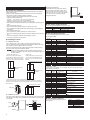
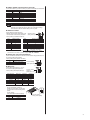
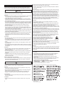
HL-14067-2 OPERATING MANUAL Compact linear actuator DRL㸈 Series Thank you for purchasing an Oriental Motor product. This Operating Manual describes product handling procedures and safety precautions. • Please read it thoroughly to ensure safe operation. • Always keep the manual where it is readily available. Built-in Controller Introduction Before use Only qualified personnel should work with the product. Use the product correctly after thoroughly reading the section “Safety precautions”. The product described in this manual has been designed and manufactured for use in general industrial machinery, and must not be used for any other purpose. For the driver’s power supply, use a DC power supply with reinforced insulation on its primary and secondary sides. Oriental Motor Co., Ltd. is not responsible for any damage caused through failure to observe this warning. Names and functions of parts Front side of the driver POWER LED (green) ALARM LED (red) C-DAT LED (green) Data edit connector (CN3) C-ERR LED (red) Encoder connector (CN5) Operating manuals for the DRL㸈 series Operating manuals for this product are listed below. After reading the following manuals, keep them in a convenient place so that you can reference them at any time. • DRL㸈 Address number setting switch (SW1) Function setting switches (SW2) Motor connector (CN4) I/O signals connector (CN2) Series Actuator OPERATING MANUAL • DRL㸈 Series FLEX Built-in Controller OPERATING MANUAL (this document) Power supply connector (CN1) • CRK Series FLEX Built-in Controller USER MANUAL The USER MANUAL for this product is common with the CRK Series. This manual does not come with the product. For details, contact your nearest Oriental Motor sales office. Hazardous substances The products do not contain the substances exceeding the restriction values of RoHS Directive (2011/65/EU). Republic of Korea, Radio Waves Act DIN lever Name POWER LED (green) ALARM LED (red) Seller and user shall be noticed that this equipment is suitable for electromagnetic equipments for office work (Class A) and it can be used outside home. C-DAT LED (green) 㧊 ₆₆⓪ 㠛ⶊ㣿(A ) 㩚㧦䕢㩗䞿₆₆⪲㍲ 䕦ⰺ㧦 ⡦⓪ ㌂㣿㧦⓪ 㧊 㩦㦚 㭒㦮䞮㔲₆ ⧒Ⳇ, Ṗ㩫㣎㦮 㰖㡃㠦㍲ ㌂㣿䞮⓪ ộ㦚 ⳿㩗㦒 ⪲ 䞿┞┺. C-ERR LED (red) Checking the product Verify that the items listed below are included. Report any missing or damaged items to the branch or sales office from which you purchased the product. Address number setting switch (SW1) • Items supplied with all motor and driver package models Function setting switches (SW2) • • • • • • • Power supply connector (CN1) Actuator ..............................................................1 unit Driver..................................................................1 unit CN1 connector (3 pins).......................................1 pc. CN2 connector cable [1 m (3.3 ft.), 40 pins] .......1 pc. CN4 connector lead wire [0.6 m (2 ft.), 5 pins]....1 pc. OPERATING MANUAL (this document) .............1 copy OPERATING MANUAL (Actuator) ......................1 copy • Item supplied with the electromagnetic brake type actuator and driver package models I/O signals connector (CN2) Data edit connector (CN3) Actuator connector (CN4) Encoder connector (CN5) Description This LED is lit while the power is input. This LED will blink when an alarm generates (a protective function is triggered). The type of the generated alarm can be checked by counting the number of times the LED blinks. This LED will blink or illuminate steadily when the driver is communicating with the master station properly via RS-485 communication. This LED will illuminate when a RS-485 communication error occurs with the master station. This switch is used to set the address number of RS-485 communication. No.1 to 3: Sets the baud rate of RS-485 communication. No.4: Sets the connection destination of RS-485 communication. Connects the main power supply (+24 VDC) with the supplied connector. Connects I/O signals with the supplied lead wire/connector assembly. Connects a PC in which the MEXE02 has been installed, or the OPX-2A. Connects the actuator. Not used. Upper side of the driver • Varistor ...............................................................1 pc. • Item supplied with the connector-coupled actuator and driver RS-485 communication connector (CN6/CN7) package models Applicable product: All models for the DRL20/DRL28 and models of high-resolution motor for the DRL42/DRL60 • Actuator connector leads [0.6 m (2 ft.), 5 pins] ...1 pc. Terminal resistor setting switch (SW3) Name Termination resistor setting switch (SW3) RS-485 communication connector (CN6/CN7) Description This switch is used to set the termination resistor (120 ) of RS-485 communication. Connects the RS-485 communication cable. 1 Installation Removing from DIN rail Location for installation The actuator and driver has been designed and manufactured to be installed within another device. Install it in a well-ventilated location that provides easy access for inspection. The location must also satisfy the following conditions: • Inside an enclosure that is installed indoors (provide vent holes) • Operating ambient temperature Actuator: -10 to +40 °C (+14 to +104 °F) (non-freezing) Driver: 0 to +40 °C (+32 to +104 °F) (non-freezing) • Operating ambient humidity 85% or less (non-condensing) • Area that is free of explosive atmosphere or toxic gas (such as sulfuric gas) or liquid • Area not exposed to direct sun • Area free of excessive amount of dust, iron particles or the like • Area not subject to splashing water (rain, water droplets), oil (oil droplets) or other liquids • Area free of excessive salt • Area not subject to continuous vibration or excessive shocks • Area free of excessive electromagnetic noise (from welders, power machinery, etc.) • Area free of radioactive materials, magnetic fields or vacuum • Up to 1000 m (3300 ft.) above sea level Installing the driver Installation direction Use a DIN rail 35 mm (1.38 in.) wide to mount the driver. Provide 50 mm (1.97 in.) clearances in the horizontal and vertical directions between the driver and enclosure or other equipment within the enclosure. Refer to the figure below for the required distances between adjacent drivers when two or more drivers are installed in parallel. Note Be sure to install (position) the driver vertically. When the driver is installed in any position other than vertical, the heat radiation effect of the driver will drop. • LRD503-KD, LRD507-KD Two or more units can be placed in contact with each other in the horizontal direction. Provide a clearance of 50 mm (1.97 in.) or more in the vertical direction. • LRD514-KD Provide a clearance of 20 mm (0.79 in.) or more in the horizontal direction, and 50 mm (1.97 in.) or more in the vertical direction. 20 mm (0.79 in.) or more Pull the DIN lever down until it locks using a flat tip screwdriver, and lift the bottom of the driver to remove it from the rail.Use a force of about 10 to 20 N (2.2 to 4.5 lb.) to pull the DIN lever down to lock it. Excessive force may damage the DIN lever. Pin assignments lists CN1: Power supply connector Connect using the supplied CN1 connector (3 pins). Pin No. 1 2 3 Name +24 VDC GND FG Description +24 VDC power supply input Power supply GND Frame Ground CN2: I/O signals connector Connect using the supplied CN2 connector cable. Upper ribbon cable Lead wire color Brown-1 Red-1 Orange-1 Yellow-1 Green-1 Blue-1 Purple-1 Gray-1 White-1 Black-1 Brown-2 Red-2 Orange-2 Yellow-2 Green-2 Blue-2 Purple-2 Gray-2 White-2 Black-2 Pin No. A1 A2 A3 A4 A5 A6 A7 A8 A9 A10 A11 A12 A13 A14 A15 A16 A17 A18 A19 A20 Signal name IN-COM0 START ALM-RST AWO STOP M0 M1 M2 M3 M4 M5 HOME/P-PRESET FWD RVS +LS LS HOMES SLIT N.C. IN-COM1 Description Input common Start input Alarm reset input All windings off input Stop input Data selection input Return-to-home/position preset input Forward input Reverse input + limit sensor input limit sensor input Mechanical home sensor input Slit sensor input Not used Sensor input common Lower ribbon cable Control output 1 to 4 settings can be changed using the “OUT1to OUT4 signal mode selection” parameters. 50 mm (1.97 in.) or more 50 mm (1.97 in.) or more • When using the LRD514-KD in parallel with another driver Another unit can be placed in contact with the right side of LRD514-KD. Provide a clearance of 20 mm (0.79 in.) or more on the left side of LRD514-KD where a heat sink is located. 20 mm (0.79 in.) or more Heat sink Installation method Push up the driver’s DIN lever until it locks. Hang the hook at the rear to the DIN rail, and push in the driver. After installation, fix the both sides of the driver with the end plate. Hook DIN rail DIN lever 2 End plate Lead wire color Brown-3 Red-3 Orange-3 Yellow-3 Green-3 Blue-3 Purple-3 Gray-3 White-3 Black-3 Brown-4 Red-4 Orange-4 Yellow-4 Green-4 Blue-4 Purple-4 Gray-4 White-4 Black-4 Pin No. B1 B2 B3 B4 B5 B6 B7 B8 B9 B10 B11 B12 B13 B14 B15 B16 B17 B18 B19 B20 Signal name MOVE+ MOVE ALM+ ALM OUT1+ OUT1 OUT2+ OUT2 OUT3+ OUT3 OUT4+ OUT4 N.C. N.C. PLS-OUT+ PLS-OUT DIR-OUT+ DIR-OUT GND N.C. Description Motor moving output Alarm output Control output 1 (initial value: AREA) Control output 2 (initial value: READY) Control output 3 (initial value: WNG) Control output 4 (initial value: HOME-P) Not used Not used Pulse output (Line driver output) Direction output (Line driver output) GND Not used CN4: Actuator connector Connect using the supplied CN4 connector cable (5 pins). Pin No. 1 2 3 4 5 Description Blue motor lead Red motor lead Orange motor lead Green motor lead Black motor lead CN6/7: RS-485 communication connector Connect this cable if you want to control your product via RS-485 communication. Pin No. 1 2 3 4 5 6 7 8 Signal name N.C. GND TR+ N.C. N.C. TR N.C. N.C. Description Not used GND RS-485 communication signal (+) Not used Not used RS-485 communication signal () Not used Not used Setting the switches Note Be sure to turn off the driver power before setting the switches. If the switches are set while the power is still on, the new switch settings will not become effective until the driver power is cycled. Address number Set the address number using the address number setting switch (SW1) and “communication axis number” parameter. Factory setting: 0 (address number 0) SW1 0 1 2 3 4 5 6 7 Address number 0 1 2 3 4 5 6 7 Address number setting switch (SW1) SW1 8 9 A B C D E Address number 8 9 10 11 12 13 14 Setting value of “communication axis number” parameter∗ F ∗ The default value of the “communication axis number” parameter is “15.” Set the “communication axis number” parameter using the OPX-2A or MEXE02. Setting the connection destination Set the connection destination of RS-485 communication using position No.4 of the function setting switch (SW2). Factory setting: OFF (network converter) SW2-No.4 ON OFF Connection destination General master device Network converter Function setting switch (SW2-No.4) Baud rate Set the baud rate using Nos. 1 to 3 of the function setting switch (SW2) to. Factory setting: All ON (625,000 bps) Baud rate (bps) 9600 19200 38400 57600 115,200 250,000 312,500 625,000 SW2-No.3 OFF OFF OFF OFF ON ON ON ON Function setting switches (SW2-Nos.1 to 3) SW2-No.2 OFF OFF ON ON OFF OFF ON ON SW2-No.1 OFF ON OFF ON OFF ON OFF ON Termination resistor Set the Termination resistor for RS-485 communication (120 ) using the Termination resistor setting switch (SW3). Factory setting: OFF (Termination resistor disabled) SW3 OFF ON Termination resistor (120 ) Disabled Enabled OFF ON Terminal resistor setting switch (SW3) 3 Safety precautions The precautions described below are intended to prevent danger or injury to the user and other personnel through safe, correct use of the product. Use the product only after carefully reading and fully understanding these instructions. • Keep the area around the actuator and driver free of combustible materials. Failure to do so may result in fire or skin burn(s). • Provide a cover over the moving part (screw shaft) of the actuator. Failure to do so may result in injury. Connection Warning Handling the product without observing the instructions that accompany a “Warning” symbol may result in serious injury or death. General • Do not use the product in explosive or corrosive environments, in the presence of flammable gases, locations subjected to splashing water, or near combustibles. Doing so may result in fire or injury. • Assign qualified personnel the task of installing, wiring, operating/controlling, inspecting and troubleshooting the product. Failure to do so may result in fire, injury or damage to equipment. • The actuator will lose its holding torque when its excitation or the power supply is turned off. Take measures to keep the moving part in position if the product is used in vertical operations such as elevator applications. Failure to provide such measures may cause the moving parts to fall, resulting in injury or damage to equipment. • Do not use the brake mechanism of the actuator with an electromagnetic brake for stopping or for safety purposes. The electromagnetic brake is used for the purpose to hold the moving part and actuator in position. Failure to do so may result in injury or damage to equipment. • With certain types of alarms (protective functions), the actuator may stop when the alarm generates and the holding torque will be lost as a result. This may result in injury or damage to equipment. • When the alarm is generated, first remove the cause and then clear the alarm. Continuing the operation without removing the cause of the problem may cause malfunction of the actuator and driver, leading to injury or damage to equipment. Connection • Keep the input power voltage of the driver within the specified range. Failure to do so may result in fire. • For the driver power supply, use a DC power supply with reinforced insulation on its primary and secondary sides. Failure to do so may result in electric shock. • Connect the cables securely according to the wiring diagram. Failure to do so may result in fire. • Do not forcibly bend, pull or pinch the cable or lead wire. Doing so may cause fire. Repetitive stress or overstress on the connection part may cause damage to the product. Operation • Turn off the driver power in the event of a power failure. Or the actuator may suddenly start when the power is restored and this may cause injury or damage to equipment. • Do not turn the excitation to off while the actuator operates. The actuator will stop and lose its holding power. Doing so may result in injury or damage to equipment. • Configure an interlock circuit using a sequence program so that when a RS-485 communication error occurs, the entire system including the driver will operate on the safe side. Repair, disassembly and modification • Do not disassemble or modify the actuator and driver. This may cause injury. Refer all such internal inspections and repairs to the branch or sales office from which you purchased the product. Caution Handling the product without observing the instructions that accompany a “Caution” symbol may result in injury or property damage. General • Do not use the actuator and driver beyond its specifications. Doing so may result in injury or damage to equipment. • Keep your fingers and objects out of the openings in the actuator and driver. Failure to do so may result in fire or injury. • Do not touch the actuator and driver while operating or immediately after stopping. The actuator and driver may be hot and cause skin burn(s). Transportation • Do not hold the moving part (screw shaft) of the actuator, cable or lead wire. This may cause injury. Installation • Install the actuator and driver in the enclosure. Failure to do so may cause injury. 4 • The power supply connector (CN1), I/O connector (CN2), data edit connector (CN3) and RS-485 communication connector (CN6/CN7) of the driver are not electrically insulated. When grounding the positive terminal of the power supply, do not connect any equipment (PC, etc.) whose negative terminal is grounded. Doing so may cause the driver and PC to short, damaging both. • When connecting, check the indication of the driver case and pay attention to the polarity of the power supply. Reverse-polarity connection may cause damage to the driver. The power supply circuit and the RS-485 communication circuit are not insulated. Therefore, when controlling multiple drivers via RS-485 communication, the reverse polarity of the power supply will cause a short circuit and may result in damage to the drivers. Operation • Use a actuator and driver only in the specified combination. An incorrect combination may cause a fire. • Provide an emergency stop device or emergency stop circuit external to the equipment so that the entire equipment will operate safely in the event of a system failure or malfunction. Failure to do so may result in injury. • Before supplying power to the driver, turn all control input to the driver to OFF. Otherwise, the actuator may suddenly start when the power is turned on and it may cause injury or damage to equipment. • Set a suitable speed and acceleration/deceleration rate. Improper setting may cause loss of the motor synchronism of the actuator and moving the load to an unexpected direction, which may result in injury or damage to equipment. • Do not touch the moving part (screw shaft) of the actuator while operating. This may cause injury. • Before moving the moving part (screw shaft) of the actuator directly by the hands, confirm that the power supply or actuator excitation is turned off and the actuator current is cut off. Failure to do so may result in injury. • The actuator surface temperature may exceed 70 °C (158 °F) even under normal operating conditions. If the operator is allowed to approach the running actuator, attach a warning label as shown below in a conspicuous position. Warning label Failure to do so may result in skin burn(s). • Immediately when trouble has occurred, stop running and turn off the driver power. Failure to do so may result in fire or injury. • Static electricity may cause the driver to malfunction or suffer damage. Do not touch the driver while the driver power is on. Always use an insulated screwdriver to adjust the driver switches. Disposal • To dispose of the actuator or driver, disassemble it into parts and components as much as possible and dispose of individual parts/components as industrial waste. If you have any question, contact your nearest Oriental Motor branch or sales office. • Unauthorized reproduction or copying of all or part of this manual is prohibited. • Oriental Motor shall not be liable whatsoever for any problems relating to industrial property rights arising from use of any information, circuit, equipment or device provided or referenced in this manual. • Characteristics, specifications and dimensions are subject to change without notice. • While we make every effort to offer accurate information in the manual, we welcome your input. Should you find unclear descriptions, errors or omissions, please contact the nearest office. • and are registered trademarks or trademarks of Oriental Motor Co., Ltd., in Japan and other countries. © Copyright ORIENTAL MOTOR CO., LTD. 2012 • Please contact youryour nearest Oriental MotorMotor office for further • Please contact nearest Oriental office forinformation. further information. Technical Support Tel:(800)468-3982 Technical Support Tel:(800)468-3982 A.M. to 5:00 P.M., P.S.T. (M-F) 8:30 www.orientalmotor.com 7:30 A.M. to 5:00 P.M., C.S.T. (M-F) E-mail: [email protected] Tel:+55-11-3266-6018 www.orientalmotor.com www.orientalmotor.com.br Headquarters and Düsseldorf Office Headquarters Düsseldorf, Germany Tel:0211-52067-00 Fax:0211-52067-099 Technical Support Tel:00 800/22 55 66 22 Munich Office www.orientalmotor.de Tel:089-3181225-00 Fax:089-3181225-25 Hamburg Office Tel:01256-347090 Fax:040-76910445 Tel:040-76910443 www.oriental-motor.co.uk Tel:01256-347090 Fax:01256-347099 Tel:01 47 86 97 50 Fax:01 47 82 45 16 Tel:02-93906346 Fax:02-93906348 Tel:400-820-6516 Singapore Fax:021-6278-0269 Tel:1800-8420280 www.orientalmotor.com.sg Tel:(02)8228-0707 Tel:1800-806161 Fax:(02)8228-0708 www.orientalmotor.com.my Tel:+65-6745-7344 Fax:+65-6745-9405 Tel:1800-888-881 www.orientalmotor.co.th Tel:(03)22875778 Fax:(03)22875528 Tel:+91-80-41125586 Tel:+66-2-251-1871 www.orientalmotor.co.in Fax:+66-2-251-1872 Tel:0800-060708 www.orientalmotor.com.tw KOREA Tel:400-820-6516 Tel:080-777-2042 www.orientalmotor.com.cn Fax:02-2026-5495 Tel:01 47 86 97 50 www.orientalmotor.fr Tel:02-93906346 www.orientalmotor.it Headquarters Tokyo, Japan Tel:03-6744-0361 www.orientalmotor.co.jp Korea Headquarters Tokyo, Japan Tel:080-777-2042 www.inaom.co.kr Tel:03-6744-0361 Fax:03-5826-2576 Hong Kong Branch Tel:+852-2427-9800