1
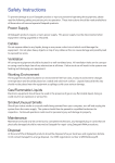
X 4 D VI S p litte r P lu s
USER M ANUAL
Revised: Feb 6, 2015
Contents
Safety Instructions
3
Introduction
4
Configuration Examples
5
Unpacking
9
Description
10
Setting up the x4
13
Configuring the x4
14
Operating Instructions
16
x4 Display Designer Application
17
Specification
26
Limited Warranty and Contact Information
27
Index
28
Safety Instructions
To prevent damage to your ProPlex product or injury to personnel operating the equipment, please
read the following safety precautions prior to operation. These instructions should be made
available to all those who will use and operate ProPlex products.
Power Supply
This product requires a mains power cable (supplied). This power cable must be disconnected
when equipment is being upgraded or relocated.
Cables
Do not expose cables to any liquids; doing so may cause a short circuit which could damage the
equipment. Do not place heavy objects on top of any cables as this can cause damage and
possibly lead to exposed live wires.
Ventilation
All computer equipment should be located in a well ventilated area. All ventilation holes on the
unit casing must be kept clear of any obstruction at all times. Failure to do so will result in the
system over heating and damaging your equipment.
Working Environment
The equipment should be located in an environment free from dust, moisture and extreme
changes in temperature and should be placed on a stable and solid work surface. Liquids (hot/
cold drinks etc) should not be placed near the equipment as spillage could cause serious damage.
Gas/Flammable Liquids
Electronic equipment should never be used in the presence of gas or any flammable liquid, doing
so could result in an explosion or serious fire.
Smoke/Unusual Smells
Should you notice smoke or unusual smells being emitted from your computer, turn off and unplug
the system from the mains supply. The system should then be passed to a qualified technician for
inspection. Continued operation could result in personal injury and damage to property.
Maintenance
Maintenance should only be carried out by competent technicians, any ProPlex products that are
physically damaged should be returned to TMB for repair using TMB RMA procedures.
Disposal
At the end of life all ProPlex products should be disposed of as per local laws and regulations
dictate.
3
Introduction
The ProPlex X4 is a stand alone display wall controller that accepts a standard single or dual-link
DVI input and can flexibly display this across four output monitors.
Each output can be driven as DVI or analog RGB, and can represent an arbitrary crop region
of the original input image. The output resolution and frame rate does not need to be related to
that of the input as the ProPlex X4 will optionally upscale and frame-rate convert each cropped
region independently. However, if the ProPlex X4 detects that frame rates identically match
it will automatically frame-lock all outputs and if possible, frame-lock these to the input signal.
Additionally, each output can be independently mirrored or rotated through 90°, 180° or 270° to
support creative mixes of landscape and portrait monitors.
The ProPlex X4 is also ideal for use with edge blending projectors, supporting image overlapping.
4
Configuration Examples
Listed on the next few pages are just a few examples of what can be achieved with the ProPlex
X4. The list of examples is not definitive and users are encouraged to experiment with different
display configurations
Duplicate the input signal x4 and display each duplicate on separate screens
5
Divide the input signal into quadrants and display each quarter on separate displays with optional
frame rate conversion (in this case 30Hz to 60Hz). Crop regions can be adjusted to provide
monitor bezel compensation.
6
Duplicate the input signal x2 and display 1 on a single landscape display and divide the 2nd into
thirds, rotate to portrait, upscale and split between 3 displays.
Crop input signal, upscale specific areas and display on 4 separate screens.
7
Crop the input signal into x4 and display x2 quarters landscape and x2 quarters portrait.
Crop the input signal x4 rotate through 90º,180º or 270º, display in landscape and portrait.
Arbitrary crop regions can allow the monitors to be artistically arranged, but maintain an
undistorted image.
8
Unpacking
Your packing box should contain the following items:
• 1x ProPlex X4 DVI Splitter Plus display controller
• 1x PowerCon power cord
• 1x USB-A to USB-B cable
Note:
We recommend that you do not discard the packing box until you are completely satisfied
with the X4 and it is fully installed and working correctly. We also recommend that you
make note of the serial number of the controller in a prominent place before you connect it
to the computer. This should hasten any query should you need to contact our Technical
Support Department. The serial number is displayed on the X4 and the box label.
9
Description
Front panel
Fig.1
Operation Indicators
The front panel has three LEDs to indicate the operational status of the X4:
• Power
• Input
• Status
Power
• When illuminated, the Power LED indicates the X4 is connected to a mains supply using the
supplied PSU.
Input
• When illuminated, the Input LED indicates a valid DVI source is connected.
Status
• Continuous illumination – Indicates the X4 is operating normally.
• Flashing – Unit is operating over the normal operating temperature. Ensure the input fan vent
is not blocked.
• If the Status LED goes off and remains off this indicates that the settings configured in the X4
application no longer match the input, this is normally the result of a change of input. The X4
will compensate for the settings and reconfigure itself to display as near to the settings as possible. The output will still be displayed but not necessarily as expected.
When the X4 device is connected to a PC by a USB cable and the X4 Control application is active,
then all three lights flash in turn to help to identify which unit is being controlled.
10
Output Framelock
The Output Framelock is intended to ease the setup of the X4 by setting all four outputs to the
exact same timings by replicating the the timings of the first output.
Push and hold the button for approx 3 seconds to activate the Output Framelock. (The three
LEDs will flash to indicate the operation is successful).
If the first output is set to “Use The Monitor’s Preferred Mode”, the EDID timings will be sampled
from the monitor, and written into the X4 defaults. Output 1 will then be set to “Always Use the
Default Mode”.
If output 1 is set to “Always Use the Default Mode”, no action is taken on this channel.
Output 2,3, and 4 will have their timing defaults overwritten with those from Output 1 and they will
also be set to “Always Use the Default Mode”.
The onboard micro in the X4 will then enable the framelocking.
The X4 will now ignore the output monitor connections until it is changed using the X4 application.
Rear Panel
Fig.2
USB Socket
There are USB ports on the front and back to be used to connect the X4 to a PC via a USB
connection using the supplied USB Type A to Type B cable. Either port can be used at any time.
Configuration of the X4 is programmable via the ProPlex Display Designer application allowing
easy control of cropping, scaling, rotation and gaps.
11
DVI-D Input Socket
The DVI-D Input socket is used to connect the DVI input source to the X4. The X4 supports Dual
Link DVI, Single Link DVI and also HDMI (not HDCP compliant) by using the optional DVI/HDMI
Adapter.
DVI-I Output Sockets
The four DVI-I Out sockets are used to connect the X4 to the output monitors. The X4 supports
both DVI and analog RGB monitors.
Power
The PowerCON power socket is where the power source is connected to the X4. The included
PowerCON cable connects here. The power LED on the front of the X4 illuminates when a power
supply is connected.
Fuse
A 1Amp glass fuse is required for operation. Do not use a different size fuse or attampt to bypass
the fuse or damage may result and the warranty will be void.
12
Setting up the X4
• Ensure the power supply for the DVI source is disconnected.
• Connect the cable from the DVI source to the input socket on the rear of the X4.
• Connect the four displays to the output sockets on the rear panel of the X4.
• Connect the PowerCON Cable.
• Power up the DVI source.
The Power LED located on the front panel will illuminate to indicate that power has successfully
been applied to the unit.
The X4 incorporates an internal processor that will continuously monitor the received DVI signal,
and whenever a valid and stable input is detected the Input LED is illuminated.
If the Input LED is not illuminated, the X4 cannot detect a valid DVI input source.
During operation, the X4 is able to adjust its internal operation to maintain the programmed output
proportions even when the input resolution changes.
Fig.3
13
Configuring the X4
Factory Default Settings
The X4 stores a number of parameters to configure its operation. This allows it to operate stand
alone in a very flexible manner. The configurations affect the input and output display modes as
well as the required partitioning of the input image between monitors.
By default the X4 is configured as follows:
Input EDID Preferred Mode: 1920 x 1080 x 60Hz (SMPTE timings)
Output monitor mode:
Use Monitor Preferred Mode
Default : 1920 x 1080 x 60Hz (SMPTE)
2x2 equal split (960x540)
Cropping Mode: No Rotation
The default settings are changed using the ProPlex Display Designer Windows® application,
which can be run on any Windows® platform and connected to the X4 via the supplied USB cable.
A description of the use of the application is provided in the X4 Control Application section.
A Command Line Interface utility is also available for Mac OS x 10.6
The sections below describe the settings that are possible and why they may be needed. For
details on how to program the X4 hardware with your desired configurations, please see the X4
Display Designer section.
Configuring DVI Input resolution
Because the timings and resolution of the DVI input are set by the DVI source machine, the X4
can only configure this indirectly by presenting a programmable “Preferred Mode” as part of its
EDID (Extended Display Identification Data).
Most graphics cards and HDMI appliances automatically select the “Preferred Mode” resolution
and timings presented by the X4 EDID, but they may need to be forced to re-detect if the EDID
contents are changed by the X4 application. This would typically be via a hot-plug event caused
by disconnecting and reconnecting the DVI input cable.
The configuration application will allow read back of the resolution that is currently being detected,
as well as the ability to read and write the internal EDID rom.
14
Monitor Outputs
The X4 can be configured to read the corresponding EDID of each monitor that is connected and
to drive out a signal that corresponds to the resolution, timings and mode (RGB or DVI) of the
Preferred Mode. This is the factory default configuration.
Please note that when different monitors are attached to the four outputs, each may advertise a
different Preferred Mode, therefore each output will be driven at a different mode.
Whenever the monitor EDID is used, the X4 will calculate the internal scale factors to ensure that
the monitor (at whatever resolution it is being driven) will still display the correct proportion of the
input image.
If an EDID cannot be read (for example if the monitor cable does not support the DDC signals
required), there is a default mode that can be programmed into the X4s memory. This is factory
configured to 1080p.
In some cases it may be that the user requires a very specific output timing (for example when
frame-locking to the input) irrespective of the monitor EDIDs. In this case the X4 can be
configured to always output the mode that has been programmed as the default mode.
Selecting the Regions to Be Displayed
Each output of the X4 can take its display data from any arbitrary rectangular region of the
captured input image. The factory default for these cropping rectangles configures the four
monitors to display a quarter of the input as a 2x2 array, and these proportions are maintained
across different input resolutions.
For a 1080p input, this means that 960x540 pixels from the input image would be up scaled by a
factor of 2 in each direction if the selected output resolution was 1080p.
However if the input resolution were to change to 1600x1200, then for the same output monitor
the X4 would upscale from an 800x600 region and would reprogram its scale factors to 2.4
horizontally and 1.8 vertically to support the same 1080p monitor.
The cropping regions can be assigned arbitrarily and can overlap, the only restriction being that
the resulting scale factor must be greater than 1.0 (ie 1:1 or up scaled) in either direction. As an
example it is possible to use the X4 to output four identical copies of the input signal (providing the
resulting output timings remain within the capabilities of the single-link DVI outputs).
The regions of the input image to be displayed on a given output monitor can be programmed via
USB by using the ProPlex Display Designer application.
In order to support portrait orientation of monitors, the source data can be rotated by 90º, 180º or
270º as it is output to the monitor.
15
Operating Instructions
DVI Input
When the X4 is powered up successfully and the Power, Input and Status LED indicators are
illuminated; this indicates that a DVI input mode has been detected and is working normally.
If the Input LED indicator is not on, check to ensure a single or dual link DVI cable is correctly fitted to the appropriate sockets.
At high resolution, DVI signals cannot normally be guaranteed beyond 5m cables due to the nature of the signal losses inherent in the DVI cables and connectors. Active equalization hardware
on the X4 compensates for these losses and supports cable lengths up to 20m even at full duallink resolutions (330Mhz pixel clocks). Lower resolutions will allow even longer cable lengths.
This allows more flexible positioning of the X4 relative to the source and the displays.
Once the LED indicators are illuminated, the X4 will display the source across all four screens according to the configuration that is stored in its non-volatile memory. The X4 is factory configured
to display the input image as a 2x2 split as shown in Fig.3.
Output
To connect to an analog output, a DVI-I-VGA cables are required. To connect to a DVI output, a
DVI-D cable is required.
Configuring the X4
The X4 has a USB port to allow a host PC to connect to the X4 box and for the user to program its
configuration. Once configured the X4 will run stand-alone without the need for the USB connection and will auto detect input resolutions and adjust internal scaling to drive the output monitors
consistently.
Frame-lock
The Firmware running on the X4 will detect when input and/or output timings are set to identical
frame rates and will automatically frame-lock the syncs in these cases. In all frame-lock modes,
the timings are configured to share a common reference clock, so there will be no drift in synchronisation, and therefore no requirement for continual adjustment that can sometimes upset LCD
panels. The frame-lock status is shown in the X4 Control Application.
16
X4 Display Designer Application
Application Installation
Note: Do not plug the X4 into a USB port until the driver installation is complete.
Download the Display Designer software for the ProPlex X4, run install.exe. and follow the
installation wizard. During installation a warning message is displayed stating that the driver does
not have Windows® Logo accreditation.
Select Continue Anyway to complete the installation.
The ProPlex X4 can now be connected to a suitable USB 1.0 or 2.0 port using the cable supplied.
At this point the hardware will be detected by Windows® as a USB API, and a New Hardware wizard is displayed. Allow the wizard to search, and click on the recommended option to enable the
previously installed driver to be associated with the new hardware.
Press Continue Anyway to accept the driver.
Running the Display Designer Application
To open the X4 Control application select Start/All Programs/Display Designer.
The application will search for an X4 connected to your computer and display the status of the first
X4 detected. Should there be more than one X4 in use, a list of all available X4s can be found in
the File menu.
Once the application has detected an X4 the main status screen is displayed Fig.4.
Fig.4
17
The main control dialog is divided into the following groups:
Connection Diagram
DVI-D Input
Input Capture Regions
Device
Monitor Outputs
Connection Diagram
The connection diagram displays a schematic view of the rear panel of the X4 to assist in
identifying the connectors.
Fig.5
Device
The unique USB device name that is connected is displayed in the Device group. It is possible
to associate a more user friendly name such as “First Four Outputs”. The friendly name is stored
in non-volatile storage on the X4 and can to help identify the device during future configurations.
Specific devices connected to your PC can be selected using the Select Device.. command on the
File Menu. The X4s will be listed by the USB Device or by a previously configured friendly name.
Fig.6
18
DVI-D Input
The DVI-D Input group displays the current DVI mode that is being captured (if any) and the
preferred mode that has been programmed into the X4s EDID. Use the Modify button to update
the EDID. The small square to the left of the current input resolution indicates whether the X4 has
frame-locked to the input source.
• Green – The outputs are frame-locked to the input dot clock and vertical sync
• Grey – The outputs are not frame-locked
Fig.7
To boost the equalization hardware click on the Settings button and the following dialog is
displayed. Fig 8.
Fig.8
Use the slider to compensate for the loss signal quality due to DVI cable lengths over 5 m. The
equalization hardware can compensate for cables up to 20m in length.
To change the timings of the input EDID click on the Modify button and the following dialog is
displayed. Fig 9.
19
Fig.9
The DVI-D Input dialog displays the resolution of the current mode for reference and allows the
timings of the EDID preferred mode to be edited. To populate the EDID timings with the current
timings click on the Copy Timings button.
The dialog supports standard timing formulae such as:
• VESA CVT
• VESA CVT Reduced Blanking
• SMPTE (for HD modes)
• VESA GTF
• Custom
Selecting Auto from the drop down list will typically default to the VESA CVT algorithm which best
matches typical standard VESA output modes. However, to minimise dot clocks and hence maximise DVI cable lengths, the CVT Reduced Blanking is recommended.
Selecting Custom allows the timing parameters to be edited. It should be noted that you will need
to select between definition of Pixel Clock or Vertical Refresh since these are mutually exclusive
parameters.
Once edited, clicking OK writes the preferred mode into the EDID but may not normally affect the
input mode that is being captured. It may be necessary to force the graphics device in the host
machine to detect the new modes, this can be done by selecting Detect on the Screen Resolutions
dialog box (Windows® 7) or by disconnecting the source from the X4 and reconnecting.
20
All modifications to the Input settings can be saved as part of a .vqs file, removing the requirement
to input the same settings again. To save the settings select the Save… command in the File
menu. To open a saved .vqs file select the Open… command.
Limitations
Fig.10
Figures entered as the Input EDID Prefered Mode may exceed the internal bandwidth limitation of
the X4, if this happens a warning is displayed in the form of the figures being highlighted pink, as
shown in Fig.10
21
Input Capture Regions
Each output of the X4 can select a different region of the input source image. This dialog (Fig. 11)
displays the settings of each region (region 1 corresponds to output 1 etc). The numbers denote
the top, left, width and height coordinates of the region that is to be displayed. Note that these
are described in terms of the current active input resolution. If the input resolution changes,
the capture region coordinates scale to the new input resolution in order to maintain the same
proportions.
Fig. 11
To modify any of these settings click on Modify to display the edit dialog (Fig. 12).
Fig.12
22
Predefined Regions
For ease of use, there are preset buttons to select the two most popular configurations: Quarter or
Replicate.
Quarter
The first monitor displays the top left hand corner of the input image, the second monitor the top
right, the third the bottom left etc. This mode of operation can be used to drive four monitors in a
2x2 arrangement from a single high resolution input.
Replicate
Each output displays the entire input image. The output monitors can be driven at the same
resolution (with different timings if necessary) or a higher resolution.
There are no restrictions (other than the resulting scale factor must be 1:1 or upscale) in the region
settings, so it is possible to have regions overlapping, or to program in gaps etc. Additionally each
region can have a transform such as rotation or flipping applied to it (after cropping) in order to
support different output monitor orientations.
Please note that there may be instances where a setting stored in non-volatile memory which
was valid when it was stored (ie the scale factors from input to output were 1:1 or greater) may
subsequently require down-scaling if the resolution of the input increases. In this case the
firmware will adjust the scaling factors to give a 1:1 crop of the input, centred on the original
region. In order to indicate that at least one output is no longer exactly honouring the programmed
region setting, the front panel status light will not be illuminated.
Scaling Optimization
Scaling Optimization is used to optimise displays that have been scaled. If the display is mostly
text based, Text should be selected. This will ensure that the displayed text remains sharp after
scaling. If the display is video based select Video. Scaling optimization will ensure a smooth, unpixellated display of video.
All modifications to the Region settings can be saved as part of a .vqs file, removing the
requirement to input the same settings again. To save the settings select the Save… command in
the File menu. To open a saved .vqs file select the Open… command.
Monitor Outputs
The Monitor Outputs group shows the actual resolution and refresh rate that each of the four X4
outputs is currently providing. To see more information such as whether this is an analog RGB
or DVI mode, if it is the monitor EDID preferred mode or a default mode programmed into the X4,
along with detailed timing information, click on the Modify button for the required output.
The frame-lock status is indicated by the small coloured squares:
23
Green
The outputs are frame-locked to the Vsync of the first monitor, using a common reference clock.
If the Input frame-lock light is green (see above), then the reference clock is taken from the input
DVI source, and the system is fully frame-locked to this source. If the input frame-locked indicator
is grey, then the outputs are frame-locked together, but are not related to the input sync.
Grey
The outputs are NOT frame-locked.
Fig.13
Individual monitor outputs can be configured by clicking on the corresponding Modify button. This
will bring up a timing dialog similar to that of the input timings. This dialog is shown in Fig.14.
Fig.14
24
The source of mode selection controls whether the X4 output should take its timing values and
resolution from the preferred mode of the monitor that is connected, or use its internally
programmed ‘default’ mode. Please note that only the internal default timings can be edited in this
dialog.
If Use the Monitors Preferred Mode is selected, but no valid EDID can be read from the attached
monitor, then the X4 firmware will program the output using the default mode timings.
The X4 application has built in test patterns to enable the user to view a display on screen without
a source connected to the X4. To display the test pattern click the Modify button on the required
output and the modify output dialog is displayed (Fig.14). Activate the Test pattern generator by
sececting On and use the drop down menu to select the required test pattern (see Fig.14).
Note:
The test pattern functionality is only available on software release Version 2.0.12 onwards.
Detailed information on upgrading your X4 can be found in the latest X4 software download
available on the TMB website.
The rest of the dialog is identical to that for setting the Input timings, with the exception that for the
output monitors it is possible to select Analog RGB (“VGA”) output as well as DVI.
All modifications to the Output… settings can be save as part of a .vqs file, removing the
requirement to input the same settings again. To save the settings select the Save… command in
the File menu. To open a saved .vqs file select the Open… command.
Finally there is a Test button which should be used when defining a default mode that you are not
sure the attached monitor can support. In test mode, the output timings are programmed, but they
are not saved to non-volatile memory on the X4 until the OK button is pressed to accept the mode.
25
Specification
Physical Dimensions
438 x 173 x 40mm [17.24” x 6.81” x 1.57”]
Operating Temperature Range
Power Requirements
Cooling
0 - 35 DegC/32 - 96 DegF
5V DC, 18W via Internal PSU
The unit contains a cooling fan. The input
and output vents should not be restricted
Full speed (12Mbits/s) operation supported
To 330 Mpixels/s
4k x 4k maximum
To 165Mpixels/s
Up to 2.5Mpixel (maximum 2048 pixels in
either direction)
Up to 64 x Non-integer scale factors allowed
Updates supported via USB
3 years
USB 2.0
1 x Dual link DVI capture
Input Surface
4 x Single link DVI or analog RGB outputs
Output Screens Resolutions
Arbitrary Up Scaling
Firmware Support
Warranty
26
Limited Warranty
ProPlex X4 DVI Splitter is warranted against defective materials or workmanship for a period of 36
months (3 years) from the date of shipment.
Parts and components that are not the product of the Seller (TMB) shall be subject only to the
terms of any warranty that may be extended by the original manufacturer. Seller’s warranty shall
be restricted to the repair or replacement of any part that proved to be defective and for which a
claim is submitted to the Seller before the expiration of the applicable warranty periods.
This warranty shall not apply to any defect arising from accident, misuse or improper or
unauthorized adjustment or repair. No warranty is given with respect to color media or lamps, or
with respect to normal wear and tear.
Any claim for defective merchandise, imperfect manufacture, shortage in count, or for any other
defect known by the Customer to be existing at time of delivery is waived by the Customer unless
made in writing within 30 days after delivery.
All warranty parts will be charged to the customer until faulty parts (or product) are returned to
TMB for valuation. These parts must be returned within 30 days of receipt or warranty is void and
parts/shipping become billable items.
Seller will not assume any responsibility for any labor expended or materials used to replace
and/or repair any equipment without Seller’s prior written authorization. Any labor charges for
repairing or replacing equipment in the field will be negotiated only between the Seller and general
contractor. Freight terms on warranty repairs are FOB Seller’s warehouse or factory. If warranty
parts and/or repairs are required, Seller agrees to pay destination ground freight charges on the
aforementioned items leaving the Seller’s facility.
Contact Information
GENERAL INFORMATION
TMB
24/7 TECHNICAL SUPPORT
TMB
US Phone:
Fax:
UK Phone:
Fax:
e-mail:
web:
US/Canada:
Toll-free UK:
International:
e-mail:
web:
27
+1 818.899.8818
+1 818.899.8813
+44 (0)20.8574.9700
+44 (0)20.8574.9701
[email protected]
www.tmb.com
1 877.TMB.DUDE (+1 877.862.3833)
0800.652.5418
+1 818.794.1286
[email protected]
www.tmb.com/products/ProPlex/DDD
Index
A
F
Application Installation 17
Firmware Support 26
Arbitrary crop 4
H
B
Hardware wizard 17
Bezel compensation 6
HDMI 12
C
I
Cables up to 20m 19
Input LED 10
Configuration 14
Input socket 12
Configuring the X4 16
Input Surface 26
Connecting the X4 13
L
Connection diagram 18
LED’s 10
Cooling 26
Limitations 21
Contact Information 27
M
Crop regions 6
Mac OS 14
D
Mirrored 4
Default Settings 14
Models Available 26
Device name 18
Modify button 23, 24
Display orientations 5
Monitor Outputs 23
Dual Link DVI 12
O
DVI-D Input 19
Onboard micro 11
E
Operation Indicators 10
Edge blending 4
Output Framelock 11
EDID Preferred Mode 14
Out sockets 12
Edit dialog 22
Equalization 19
28
P
U
Physical Dimensions 26
Upgrading your X4 25
Power LED 10
Up Scaling 26
Power Requirements 26
USB socket 11
Power socket 12
W
Power Supply 3
Warranty 26
PSU Blades 9
Windows 17
Q
Windows 7 20
Quarter 23
R
Rear Panel 11
Regions to be displayed 15
Replicate 23
Rotate to portrait 7
S
Safety precautions 3
Scaling Optimization 23
Single Link DVI 12
Status 10
Status LED 10
T
Technical Support 27
Test button 25
Test patterns 25
29