1
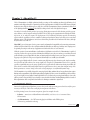
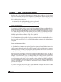
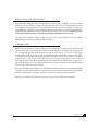
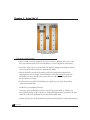
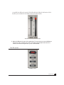
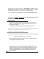
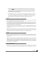
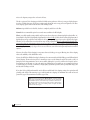
L1
UltraMaximizer
Table of Contents
Chapter 1 ........................................ About the L1......... 3
L1 component plug-ins ................... 3
Chapter 2 ............... Some secrets of digital audio......... 4
About maximum level ................... 4
About maximum resolution ................... 4
Why use them, and what are they? ................... 5
A bit about IDR (Increased Digital Resolution) ................... 5
Chapter 3 ........................................ Using the L1......... 6
The peak limiter section ...................... 6
The IDR section ...................... 7
Basic control of IDR ...................... 8
An example of IDR resolution improvement ...................... 9
Type1 ...................... 9
Type2 .................... 10
Noise-shaping options .................... 10
Chapter 4 ............................ Important IDR Info....... 11
Recommended IDR settings ................. 12
Chapter 5 ...... 16-bit (and higher) mastering (CD/DAT) ........ 13
Chapter 6 ................ 8-bit multimedia mastering....... 14
First: ......................................... do all other processing, including sample rate conversion ................. 14
Second: ............................................................................................... choose IDR settings ................. 14
For lowest noise ................. 14
For higher resolution ................. 14
For highest resolution ................. 14
Third: .................................................................................................. reduce the bitdepth ................. 14
Chapter 7 ...................................... Use the L1 last....... 15
L1 Plug-In Manual
1
Chapter 8 ..... Important notes on digital clipping....... 16
Peak-normalized signals ................. 16
Practical Precautions ................. 17
Chapter 9 ..................... L1 Controls descriptions....... 18
Quantize ................. 18
16-bit ................. 18
8- and 12-bit ................. 18
18-, 20-, and 22- bit ................. 18
24-bit ................. 18
Dither ................. 18
Shaping ................. 18
Digital/Analog Domain ................. 19
Chapter 10 ...................... Recommended settings....... 20
2
L1 Plug-In Manual
Chapter 1 - About the L1
The L1-Ultramaximizer is a highly sophisticated audio processing tool kit combining an advanced peak limiter, a level
maximizer and a high performance re-quantizer based on the implementation of Michael Gerzon’s IDR (Increased Digital
Resolution) noise-shaped re-dithering process. Why do we call it the Ultramaximizer? Because it maximizes both the level
of the digital signal and the resolution of the final file, working on both 'ends' of the digital word output.
New in the L1 is 48-bit (double precision) processing, offering improvements for all resolutions, and the opportunity to dither to a 24-bit output for archives and DVD. The L1 offers superb requantization for all bitdepths, including 24, 20 , 16, 12, and 8-bit outputs. The development of L1’s lookahead peak limiter provides the mastering
engineer with the capability to increase soundfile resolution and production master levels with precise control and
dithering options. The algorithms are carried out to their fullest potential in the L2 hardware from Waves, although
they have their roots in the L1.
Waves IDR™ process brings more choices, greater control, and unmatched compatibility to the mastering environment,
whether for high-resolution CD or low-resolution multimedia. IDR offers two dither types and three noise-shaping curves
for optimal processing in a wide variety of applications and with a wide choice of source material.
While the operation of conventional limiters is well understood, the limiter section of the L1-Ultramaximizer is capable of
a very fast, overshoot-free response, and once the limiter threshold has been set, the user can then go on to define the actual
peak level that the processed signal will reach. Once set, limiting and level rescaling becomes a one-shot process. For mastering purposes, the peak level of the processed signal would normally be set to 0dB, or just below 0dB.
Because a typical digital audio file of music contains many high intensity, short duration peaks, simple normalization of the file may still result in a low average signal level. Using the L1-Ultramaximizer however, it is generally
possible to significantly increase the average signal level of a typical audio file without introducing any audible side
effects. In the event that a deliberately limited sound is required however, there is more than adequate range of the
limiter parameters to recreate ‘vintage’ effects such as level pumping or severely limited dynamic range.
The Ultramaximizer is specifically designed for mastering, digital editing, multimedia, and any application that requires
limiting and/or requantization of the digital signal with highest quality. In order to ensure the maximum possible resolution
of a processed signal, it is very highly recommended that the L1 be used last in the processing chain. Failure to observe this
will not prevent L1 from working, but you should be aware that both the absolute brickwall limiting AND the benefits of
IDR requantization will be compromised and will need re-limiting to maintain the original level.
L1 component plug-ins
On most host applications and platforms, you can select just the audio processing you need and use only the power
necessary to do the job. The L1 has several plug-in components in the menu.
As of this printing, here are the current components, plus a few examples for each.
• L1 limiter — mono/stereo wideband limiter without IDR; (track insert, voice or instrument limiter,
SFX maximizer)
• +L1-Ultramaximizer — the "full" mastering plug-in with limiter and all IDR options.
(CD mastering, multimedia authoring)
L1 Plug-In Manual
3
Chapter 2 - Some secrets of digital audio
In order to make the best use of the L1-Ultramaximizer, it is important that we explain some of the less obvious
implications of digital audio. Once these have been explained, you will understand why Waves thought a product
such as L1 was necessary and you will be a in a better position to make use of its powerful features. The operation of
the L1 breaks down into two main areas:
1 - maximum level of the digital signal through proprietary peak control.
2 - maximum resolution of the signal through dithering and noise-shaping.
About maximum level
The maximum level of a digital signal is governed by the highest peak in the file. Simple normalization finds the
highest peak, then raises the entire signal so that this peak is at the maximum value. However, many of these peaks
may be of very short duration and can usually be reduced in level by several dBs with minimal audible side effects.
Those familiar with digital editing systems may even have proved this for themselves by ‘redrawing’ some troublesome peaks by hand. By transparently controlling these peaks, the entire level of the file can be raised several more
dB than by simple normalization resulting in a higher average signal level.
The L1-Ultramaximizer avoids the possibility of overshoot by utilizing a lookahead technique that allows the system to anticipate and reshape signal peaks in a way that produces the bare minimum of audible artifacts. Because
there is no possibility of overshoot, L1 can be used with absolute confidence in situations where brickwall limiting
is important.
About maximum resolution
Any digital signal processing that alters the original digital data (mixing, gain changes, EQ, dynamic processing,
etc.) generally increases the number of bits required to represent the signal. Conventional truncation results in a loss
of signal-resolution each time the signal is processed. The human ear uses this low level information to construct a
mental image of the stereo soundstage, so any compromise in this area manifests itself as a loss of spaciousness and
transparency. Waves’ IDR prevents this loss of critical low-level detail.
Even when processing 16-bit signals, it is normal to process with at least 24 bits resolution, or more (as in the L1,
which is now double-precision). However, as soon as the resolution is pulled back down to 16 bits by rounding or
truncation (by removing the bottom 8 bits), the resulting rounding error produces an audible distortion at low
signal levels, and a permanent loss of digital resolution that can never be recovered. If the audio signal is repeatedly
processed and truncated back to 16 bits, the losses accumulate, causing a significant loss of fidelity, most evident as
a loss of the tonal subtleties of low-level sounds within a mix. The human ear uses such low level information to
construct a mental image of the stereo soundstage, so any compromise in this area manifests itself as a loss of
spaciousness and transparency.
The solution is to properly dither and noise-shape a signal each time the wordlength is increased then reduced
(such as nearly every digital signal process will require).
4
L1 Plug-In Manual
Why use them, and what are they?
Proper dithering is simply this: before the requantization (reduction of the wordlength), a precisely controlled
amount of noise (termed ‘dither’) is added to the signal. This can convert the low-level nonlinear distortion caused
by truncation into a simple steady hiss, thereby removing all traces of low-level non-linearity, but at the expense of
a very slightly increased background noise. Obviously, increased noise levels are not ideal in high quality audio
applications, but fortunately, the perceived level of this dither noise can be greatly reduced by ‘shaping’ the noise in
such a way that it falls into an area of the audio spectrum where the human ear is least sensitive.
The main point of maximum resolution is simple: to ‘capture’ the best possible quality into a shorter wordlength
(smaller bitdepth) from a longer wordlength (higher resolution).
A bit about IDR™
IDR is a Waves proprietary noise shaping dither system developed by the late Michael Gerzon and Waves, and
signifies a major advance in preserving and actually increasing the resolution of the digital signal being processed.
You can utilize IDR each time during subsequent processes (for 16-bit storage), or once at the end of a highresolution chain (say, 24-bit), in order to ensure that the final signal has the maximum resolution possible. IDR is
of particular benefit when data is deliberately requantized from 24-bit to 16-bit, 16-bit to 8-bit and so on. Dithered
outputs of 20, 16, 12, and 8-bit are available. The current version of L1 now features double-precision resolution,
that is, that for TDM systems, all internal limiting and gains calculated with 48-bit fixed precision; on native systems, 64-bit floating precision is used. Dithering back to 24-bit output is now possible for the new DVD and other
delivery media, as well as for archives of masters.
By using the IDR implemented within the L1—Ultramaximizer, optimum results may be achieved during final file
preparation, mastering, and quantization or requantization. The greatest possible implementation of IDR available
is in the L2-hardware limiter from Waves, and features 9th-order noise shaping (the L1 has 2nd-order).
Therefore, L1 can maximize the audio level, then increase the perceived resolution of the resulting file.
L1 Plug-In Manual
5
Chapter 3 - Using the L1
The peak limiter of the L1
The peak limiter section
1 - Open a soundfile in your host application. Select part or all of the soundfile you wish to process with
the L1. Pass audio through the L1; for more information, see your host application system manual.
2 - Listen to the output of the L1. Set the threshold of the limiter by dragging the left triangle (Threshold)
down. Leave the Out Ceiling setting at the maximum value: 0.0 dB.
3 - When the threshold is exceeded by the signal, you will see the Gain Reduction indicated on the
single Attenuation meter to the right. Set the threshold about 4 to 6 dB lower than the peaks in the
Threshold meters (input). You will see that you have from 4 to 6 dB of peak limiting indicated on
the Attenuation meter (output).
4 - You’ll notice that as you pull the Threshold down, the output level goes up. Leave the Out Ceiling
setting at the maximum value:
0.0 dB. This is your maximum peak output.
Notice that you have significantly increased the output level. If your threshold is at -12dB, then you
have pushed the signal up 12 dB (not that this is recommended)! With moderate gain reduction, the maxi
mum level of a file can be significantly increased with minimal audible effect.
Only the signal above the threshold is limited; all signal below the threshold has a constant gain change that
6
L1 Plug-In Manual
is controlled by the difference between the Threshold and the Out Ceiling. It is this function of the L1
that allows you to maximize the level with the amount of headroom desired.
The release time and Attenuation meter
5 - Adjust the Release time to suit the application. For most sources, leave the Release
time set to 1.0ms; mastering: 3 to 7ms. The release time controls how fast the L1
recovers to the constant gain after a peak is encountered.
The IDR section
The IDR processor
L1 Plug-In Manual
7
After reading this overview, make sure to read the chapter - Important IDR info - which will offer you complete
IDR technical information so that you may be able to better choose from the IDR options in L1. Take the time to
read about this new technology so that you may achieve the best processing for your application.
In the L1, there are two types of Increased Digital Resolution dither technology: type1 and type2. The differences
between them will likely influence your choice for your project.
• type1 gives no nonlinear distortion.
• type2 exhibits lower dither level.
It is up to you to choose no distortion or lower dither level for your soundfile. More information is in the section
called IDR Dither Type & Noise-shaping combinations.
Basic control of IDR
• Select Quantize level for desired output (20, 16, 12, 8 bit, or no IDR) by clicking the button to toggle
through the choices. Alternately, if you option-click-hold on the Quantize button, a popup menu will
allow direct selection of bitdepth.
• Select Dither (type1, type2, non) by clicking the button.
• Select the type of noise-shaping (Moderate, Normal, Ultra, non) by clicking the Shaping button.
(The following chapter has extensive information on the combination of these 3 options.)
For optimum results, level maximization (and at least normalization) should also be done! This is why the L1
includes both advanced peak controlling and IDR together: one step maximizes both.
An example of IDR resolution improvement
To hear what truncation (an extremely severe form of quantization error) sounds like at the 1-bit level (present in
every signal, no matter the bitdepth) and how Waves’ IDR and Noise-shaping works, try this simple (and exaggerated) example:
NOTE: L1 is currently optimized for 48, 44.1, 32, and 22kHz files.
1 - Using a 16 bit, 44.1kHz soundfile, select a desired region. Select the +L1 plug-in within your application
and set your system so you can monitor the L1 output.
2 - Set Dither Type to non, and Shaping to non. Set Quantize to 8 bit for easier auditioning of
quantization distortion.
3 - Listen to the output of the L1 (preview or realtime, depending on your host application).
4 - To more easily hear the quantization error, reduce the the input level at least 30dB, until you hear the
sound becoming distorted in a 'fuzzy' way. If necessary (depending on the input level), pull the Out
Ceiling level down also, to about -15dB. Leave the Threshold at 0.0. (You will have to raise your monitor
levels quite a bit to hear the distortion noise - so do NOT click Bypass until you turn your monitor
level down!) This quantization distortion you are hearing is present in varying degrees in ALL digital
signals at the 1-bit level.
8
L1 Plug-In Manual
5 - Click Shaping twice. It changes to Normal. You will hear the music cleanly (the nonlinear distortions
are gone), and that a steady hiss in the background is now present. Of course, since you have reduced the
input level, this hiss will be much more prominent than in actual work and is exaggerated just like the
distortion. You can cycle throughout the Shaping options to listen to the quantization error-removing
effects of IDR’s different noise-shaping filters.
6 - For this example, leave Dither set to non. Audition the noise-shaping settings to familiarize yourself with
the distortion-removing properties of IDR. For 16-bit work, the flexibility of the IDR implementation of
L1 gives you the choice of dither and noise-shaping. Please read the following sections on type1, type2,
and Noise-shaping. For specific applications, see the appropriate chapter (8-bit, ≥16-bit, etc).
Type1
This is the ‘purist’ technology. It is designed for no nonlinear distortion or modulation noise at low levels and
combines optimal dither noise with psychoacoustic noise shaping.
When signals are subjected to several stages of higher-resolution processing and re-quantizing back to lower bitdepths,
the design of resolution-enhancement must satisfy different requirements than a technology designed just for onestage use. If applied several times in succession, a digital resolution enhancement technology optimized for onestage CD mastering can produce unwanted side-effects.
Waves type1 technology, however, is the first optimized for use at every processing stage, allowing for the effects of
cascading and subsequent signal processing. Type1 is also optimized to cause minimal side effects when used with
stereo signals.
Type1 is the recommended choice for use with 20 and 16 bit files processing and other high quality mastering
applications. By combining level maximization (peak controlling) and IDR processing, 16 bit files created from 20
or 24 bit masters this way can have an apparent resolution of 19 bits — an 18dB improvement.
Type2
Type2 also uses dither with a similar noise-shaping curve, but the dither is of a unique kind designed to minimize
the amount of noise added, thereby giving a lower noise level than the IDR type1 process, but at the expense of some
low level distortion.
Type2 does have some advantages for high quality mastering as well, and it is purely your choice whether the
ultimate in low distortion of type1 is preferred, or the additional reduction in dither level of type2. It may be used
for multimedia applications of all 8-bit/44.1kHz files and many 8-bit/22kHz files, dependent on source material.
Type2 is "black" with no input signal, that is, there is no dither signal if there is no input. See the 8-bit multimedia
mastering chapter for more information.
Noise-shaping options
Another way to decrease the perceived amount of noise and increase perceived resolution is to ‘shape’ the frequency
content of the noise so it matches the ear’s sensitivity curves. In basic terms, noise-shaping shifts the energy of the
L1 Plug-In Manual
9
noise to the frequency ranges where we hear it the least.
The three options of Noise-shaping provided in L1’s IDR section push more of the noise energy to higher frequencies above 15 kHz, where our ears are least sensitive, and reducing the noise energy of lower frequencies. The three
Noise-shaping options differ in the amount of this ‘shifting action’.
Moderate is provided for 8/12 bits files, but also is completely usable for 16 bit files.
Normal is the recommended option for use under most conditions for all bitdepths.
Ultra is a very high-quality setting, suitable only for use at the very last stage of mastering high-resolution files (16bit and higher) targeted for high-quality digital media. It is theoretically possible that the relatively high amount of
high frequency energy could cause undesirable side effects if the signal is going to be processed or digitally edited again.
Therefore, it is best that Ultra is used in the last stage of file preparation. However, with many thousands of L1processed products, no such situations have been reported. Since it is theoretically possible, we wish to inform you of
it. Most companies do not. These theoretical side effects might cause clicks at later edit points if ‘Ultra’ noise shaping
was used, if played back on poorly designed D/A converters. However, state-of-the-art designs rarely have these troubles
anymore.
Of course, the effect of Noise-shaping is even greater when used with type1 or type2 dithering, since Noise-shaping
reduces the audibility of the added dither noise.
Now try the full effect of IDR technology by listening to the same material, with both IDR types and different kinds
of noise shaping. The most obvious places to examine are notes or reverb during the end of the sound, or ‘tail’; it is
during this time that quantization error is most audible, although it is present on all low-level signals (such as
elements that are soft in a mix, etc). Since the entire issue of dithering is a very subtle one, we recommend you listen
to a rather long piece of audio (2-3 minutes) of high-quality, say 20-bits if possible, with a good dynamic range. Jazz
and classical recordings are ideal.
If you don’t feel you fully understand the trade-offs between IDR and Noise-shaping settings, the option that will
generally work well for CD-mastering is type1 with Normal noise-shaping. For minimum noise with 16-bit and
greater files, type2 Ultra; maximum resolution, type1 Ultra.
IDR™ technology was designed by Michael Gerzon, a Gold-medal AES
fellow, and a world authority in psychoacoustics. He also invented the
SoundField microphone, and was the major contributor to Ambisonics™.
The design of IDR is a result of his long-term researches, dating back to
1982, with many of the other leading experts in digital resolution
enhancement technologies.
10
L1 Plug-In Manual
Chapter 4 - Important IDR Info
In L1, Waves provides users with three dither options:
1 - No dither <non>. This is normal truncation and gives a high degree of nonlinear distortion at low levels.
This is what most signal processors do.
2 - IDR type1 dither. This dither adds a certain amount of noise, causing a 5 dB increase in background
noise compared to no dither, but completely eliminates all low-level distortion and signal-dependent
modulation effects. The result is a very transparent and clean low-level sound, with a very high resolution.
3 - IDR type2 dither. This dither adds virtually no audible noise, and so is 5 dB quieter than type1, but it
still gives some low-level distortion. However, this distortion is generally much lower than with no
dither at all.
There are four Noise-shaping options:
1 - None. No noise shaping, resulting in high audible hiss levels, and high distortion levels when used
without dither.
2 - Moderate. This typically reduces perceived noise by around 6 dB, and slightly reduces audible
distortion when no dither is used.
3 - Normal. This typically reduces perceived noise by around 8.5 dB, and somewhat reduces
audible distortion when no dither is used.
4 - Ultra. This gives the greatest perceived noise reduction, typically 10.5 dB.
The noise shaping options of Waves IDR differ from those in most commercial noise shapers by avoiding shapes of
noise that sound “colored” to the ear. While this gives less perceived noise reduction than in some of the most
“extreme” shapers on the market, the resulting sound is more pleasant, less colored, and takes more kindly to several
generations of processing of sound files.
The noise reduction figures given here apply to sampling rates of 44.1 or 48 kHz. At the lower sampling rates of 22 or 32
kHz, the noise shaping options are re-optimized for best results at the lower sampling rates and give smaller, but still
useful, reductions of perceived noise.
If audibility of noise were the only factor, the choice would almost always be to use Ultra noise shaping, but in some
situations, heavy noise shaping of the Ultra kind can have some disadvantages, and the alternate settings, such as
Normal or Moderate may be better.
As mentioned previously, it is theoretically possible for any extreme noise-shaper to cause trouble with cheap DA
converters. Therefore, we want to include these small notes.
L1 Plug-In Manual
11
Ultra shaping should be avoided in the following situations:
(a) Subsequent digital editing, when the signal is subjected to later editing. At the edit points, an extreme noise
shaping might cause audible “clicks”, which may be disturbing. An example application in which you would avoid
use of Ultra shaping would be on CD’s with production music or sound effects that would certainly be subject to
further digital editing.Use Normal for optimum compatibility.
(b) Poor Error Correction, i.e. when a signal is destined for a carrier medium with poor error correction, such as
CDs pressed in pressing plants with poor quality control (which are not so widespread these days). When errors
that are not properly corrected occur, the Ultra setting, like all forms of heavy noise-shaping and other resolution
enhancement technologies, might cause audible background crackles, but most especially on very cheap CD
players. While these effects generally don’t occur on the majority of mid- or hi-fi CD players, they can be noticeable on very cheap products. The amount of such crackles on poor pressings is greatly reduced by the Normal
noise shaping.
(c) If high-gain treble boost is subsequently employed. This can cause the strongly boosted higher frequencies
used by Ultra noise shaping to become so high in level that they become unpleasantly audible, or to feed excessive
noise energy into loudspeakers. Therefore Ultra shaping is best avoided in situations where subsequent heavy
equalization may be used. A much lower boost of high-frequencies is used with the Normal and Moderate noise
shapers. Ultra will not affect Dolby or broadcast encoders.
Recommended IDR settings
All of the Factory Presets (in the Load menu) are relatively self-explanatory. Keep in mind that any combination
of dither and noise shaper can be used, but the following settings are particularly recommended for different
applications and [bitdepths]:
General Purpose high-quality use, including material liable to be edited and EQ’ed: type1-Normal [24, 20, 16,
12]
Lowest Noise (CD): type2-Ultra [24, 20, 16, 12]
Low Noise/Highest quality: type1 - Ultra [24, 20, 16, 12]
Low noise while allowing editing/EQ: type2 - Normal [24, 20, 16, 12, 8 - excellent for 8/44.1 files]
High Quality, with lowest risks of spurious noises on edits or cheap CD players: type1 - Moderate [24, 20, 16, 12,
8 - excellent for 8/44.1 files]
Low noise, with lowest risk of spurious noises on edits or cheap CD players: type2 - Moderate [24, 20, 16, 12, 8 excellent for 8/22kHz files]
Lowest Noise for Multimedia (ideal for voice): non - non [8, excellent for 8/22 or 8/11 files]
Lowest Distortion for Multimedia music (good for music or continuous sound): non - Normal [excellent for 8/
22 files; not for use with 8/11]
12
L1 Plug-In Manual
Chapter 5 - 16-bit (and higher) mastering
Here are the basic steps of using L1 in a 16-bit, 44.1/48kHz application. These steps also apply to 24and 20- bit mastering.
•
All processing, EQ, sample rate conversion, dynamic changes, etc. MUST be done before L1
processing. The L1-Ultramaximizer should be the last processing of the file. Ideally, dithering occurs
only once.
• If the left and right channels need to be balanced, adjust the Input levels (separately or together) by
using the input faders.
• Using a 16 or higher bit input file, set the Threshold for desired peak limiting. For suggestions on how
much limiting to do for certain applications, see the Specific Applications chapter. In general, set
Threshold for about 4-6 dB of Gain Reduction in the Atten meter.
• Now take the Output Ceiling up to the maximum peak output you desire. You can take this Output
all the way to 0.0 dB without any clipping. For CD’s, a recommended setting is -0.3dB; for more
information read the Peak Clipping section. Factory Presets already set the Out Ceil control to the
recommended value.
• Leave the Release time set to the default (1.0 millisecond).
• Set Quantize output for 16-bit (for CD/DAT; or 20, 24, for higher archival or mastering medium if
your hardware supports the transfer of 16+ bits).
• Set Dither type (type1 or type2). IDR type1 is recommended for most high-resolution applications.
• Set Shaping (Moderate, Normal, Ultra, non). Ultra and Normal are recommended for most highresolution applications.
• Select Digital or Analog Domain mode. Analog domain is recommended for all final production
masters, as it gives a little more protection from clipping in poorly-designed DA converters without
compromising any L1 processes. For more information see Digital/Analog Domain paragraph in the
IDR controls chapter.
L1 Plug-In Manual
13
Chapter 6 - 8-bit multimedia mastering
There is no single best way to process 8-bit files because each method has its strengths and weaknesses. The best
approach for any given project depends both on your tastes and on the use to which the finished audio file will be
put. In order to provide some practical guidelines, three methods are described here which have been formulated by
top beta-testers and multimedia developers. These techniques employ peak-limiting, with optional combinations
of dithering and noise-shaping.
It is essential that your host application be able to write a physical 8-bit file on disk (we assume you're working from
16-bit files; there is very little improvement trying to use L1 on existing 8-bit files). Consult your host application
manual for details, or their tech support staff.
First: do all other processing, including Sample-Rate conversion
Second: choose IDR settings
For lowest noise
Regardless of sampling rate, for the lowest level of background noise when working with an 8-bit file, it is recommended that you use the L1’s peak limiter but without dithering or noise shaping. The appropriate IDR settings
are: Quantize-8-bit, Dither-non, Shaping-non.
For higher resolution
When working with 22kHz sampling rate music files, it is generally best to use Ultra noise-shaping and peak
limiting without dither (type1 or type2). The corresponding IDR settings are: 8-bit, non, Ultra.
This processing approach yields good results for continuous signals, such as music-only or background files.
For highest resolution
When working with 8-bit files with sampling rates of 22kHz or greater, you can use Ultra noise-shaping with
IDR type2 dithering. The appropriate IDR settings are: 8-bit, type2, Ultra. However, use will depend on the
source material.
Third: reduce the bitdepth
Some applications require specific settings to write smaller bitdepth files. Read your host application manual or
contact their tech support staff for information. The following observations are relevant when the bitdepth of a file
is being reduced–for example, if you have a 16-bit file and need to create an 8-bit final output, or if you have a 24bit file and need a 16-bit final output.
14
L1 Plug-In Manual
Chapter 7 - Use the L1 last
•
It is recommended that L1 be used as the final process after all dynamic and EQ adjustments have been
made.
•
Only when all these processes are finalized should the question of peak level be addressed. Instinctively,
it might seem appropriate to Normalize the file once all other processing has taken place, but in practice,
it may be better to set the peak levels to around 1dB below clipping using L1. For an explanation of this
reasoning, see the notes on digital clipping.
•
The choice of IDR setting depends on the final use to which the file will be put. Type1 or 2, Normal, is
recommended for most work. Type1 or 2, Ultra, is considered best for final mass production of 16bit
and greater masters, and for producing a complete disc master which will undergo no further edits. An
example of this would be a production master DAT run off from a hard disk editing system in a single
pass and where no further editing is anticipated (all timing is finalized). This DAT would then be
transferred unchanged through to the glass master.
•
When using programs such as Jam, MasterList, or MasterList CD which in effect string together
separate regions of the soundfile, you must perform destructive processing with the L1. Since
MasterList/CD is a form of editing (playing regions/songs with silence or splices between audio regions/
songs), it is recommended to use Normal noise-shaping with either Dither type1 or type2. However,
thousands of L1-processed masters have been produced with type1 Ultra with no unusual problems.
•
If you must process or EQ any previously L1-processed file, you will need to create headroom by
lowering input on those later processes, then probably re-limit to restore the average level.
L1 Plug-In Manual
15
Chapter 8 - Important notes on digital clipping
The digital words representing an audio signal at each moment have a maximum possible positive value and a
minimum possible negative value defined by the bit depth of the file format. Any attempt to force an audio signal
beyond these maximum permitted values, for example, by applying excessive gain, will result in the audio signal
being clipped. Clipping distortion generally sounds quite unpleasant and is to be avoided.
However, there are other ways in which a signal can become clipped, and some of these are far from obvious.
Peak-normalized signals
A 'Normalize’ process allows a file to be processed in such a way that the maximum peak level within the file just
reaches (but does not exceed) the digital zero or clipping point. This is obviously desirable as it means that the file is
as ‘loud’ as is possible without clipping, and in turn, this maintains the best signal-to-noise ratio, especially at low bit
word lengths.
In situations where a higher average sound level is required, L1’s peak limiter allows the typical level of signals to be
even further increased by gently pulling down the gain, without audible nonlinear distortion, of waveform peaks.
L1 can simultaneously rescale the audio data so that the limited peak signals approach or just reach digital zero.
However, by storing soundfiles at the maximum possible level, there is a risk that any subsequent processing may
take these peak levels too high, resulting in clipping distortion. Peak limiting to 0dB, by whatever means, leaves no
margin for any subsequent increase in peak level.
Intuitively, you might think that simple gain reduction could be applied without incurring the risk of clipping, and
equally that any increase in gain would be sure to cause clipping. This is true. You might also think that applying an
EQ boost at any frequency might result in clipping depending on the peak energy level within the band being
equalized. Again this is true.
What is far less obvious is that applying an EQ cut also runs the risk of causing clipping. To prove this would take a
lot of math, but the following description should help get the point across.
At any instant, the peak level of a signal may be the result of several components at different frequencies and at
different phases relative to each other. Some components will add while others will subtract, but what happens if
you ‘EQ out’ a frequency that would otherwise be subtracting from the peak level by virtue of its phase? The peak is
now higher than it was.
For most audio material, this effect will be relatively small, typically increasing peak levels of the order of 0.3 dB, but
is possible that under unfavorable circumstances or with nontypical signals, the peak level could increase significantly more than this.
If an effective peak limiter like the L1 is used, because it forces the signal to skim the peak level more often, this
likelihood of clipping in this way is further increased.
In practice, filters attenuating mid or high frequency components tend to cause the kind of increase in peak level
16
L1 Plug-In Manual
described, but high pass filters that attenuate the bass can sometimes cause much larger increases of peaks of the
order of several dBs on heavily limited signals. The phase response of certain high or low-pass filter types can also
increase peak levels by up to 4 dB or thereabouts.
Bearing in mind what’s just been said, it might seem logical to keep the signal peaking a few dB below digital zero
until all processing has been carried out. After that, you can safely normalize the signal–or can you?
A related problem with peak clipping can arise when a normalized soundfile or signal is converted to a new
sampling rate. The reason has to do with the sample-rate conversion process itself, and during sample rate reduction, the signal is effectively being filtered; the available audio frequency range is smaller at lower sampling rates.
Such filtering can increase peak sound levels in exactly the same way as attenuating equalizers can.
But even when increasing sampling rate, an increase of peak level can occur. This is because the continuous-time
audio waveform is represented in the digital domain only by its values at the sampling instants. It is perfectly
possible for the peak value of the continuous-time audio waveform to occur at instants lying between two sampling instants, and thus to be higher than the peak value at any of the sampling instants.
When changing the sampling rate, new sampling instants are chosen for the continuous-time audio waveform,
and these new sampling instants may coincide with an increased peak lying between the original sampling instants. This is especially likely to occur with signals with a lot of high frequencies, since such signal waveforms
change more rapidly between the sampling instants.
Though artificially contrived signals can be created to really show up this problem, in real life an attenuation of at
least 0.3 dB or so prior to conversion should provide adequate protection against clipping. You might expect
sample-rate-converter designers to account for the possibility by designing in a small amount of attenuation, and
the cheap ones generally do not.
But can you safely normalize a file that you know is at the final sample rate? Unfortunately not, because many
compact disc players (and some other digital consumer equipment) use oversampling digital-to-analog converters
(DACs) to produce the analog signal fed to the amplifier. Such oversampling converters involve a sampling rate
conversion process which can (and does!) cause audible peak clipping. Once again, some designers appear to have
overlooked this problem, although not as widely as they did in earlier DAC designs.
Practical Precautions
L1 incorporates an ‘analog domain’ processing mode that estimates the between-sample peak levels to reduce the
clipping risk, but even here, the process is not foolproof, so that some headroom to avoid clipping may still be
needed.
If you want to normalize and avoid clipping, normalize your files after all other processing, including sample rate
conversion. However, if you’re going to use L1 limiting, normalization may be completely redundant. In all cases,
the L1 should be used last.
L1 Plug-In Manual
17
Chapter 9 - L1 Controls descriptions
Quantize
This controls the final bit depth (8, 12, 16, 20, 24) of the output of L1. It is not related to the input bitdepth.
16-bit
If you are saving the final output to DAT or CD recorder, then set the Quantize to 16 bit; Waves plug-ins work at an
internal resolution of 24 bits or higher during all processing. The Quantize setting “captures” the best data possible
for the selected bitdepth.
8- and 12-bit
If you are saving the final output for low-resolution multimedia soundfile work, then you should set the output to
the appropriate bit depth (8 or 12 bit). The file should be sample-rate converted PRIOR to level maximization and
dithering.
20-bit
If you are saving the final output to 20-bit storage medium, set the Quantize to 20-bit.
24-bit
New feature! Now the L1 works at 48-bit resolution, and is dithered back to 24-bit when this option is chosen.
Ideal if you have a 24-bit archival medium or intend on a 24-bit file bounce for later work. In previous versions, the
signal was not dithered with this selection, and in very old versions of L1, the selection actually said "no IDR".
Dither
This controls the type of dithering process (type1, type2, non). Please read the Important IDR Info section completely for better comprehension of the options that the two modes of IDR present.
In brief:
IDR dither type1 yields lower distortion (greater linearity);
IDR dither type2 yields lower dither level.
Shaping
Noise-shaping may be selected to suit your preference for each application. Select from (Moderate, Normal, Ultra, non). Normal and Ultra are recommended for optimal result with type1; Moderate and Normal are recommended for optimal result with type2, however there are no specific restrictions! Your preference is the most
important factor.
Noise-shaping may be used without IDR being engaged, although it is not an optimal use of the technology. For
multimedia work, it is a very good option for music files. For complete information, read the Important IDR Info
section.
18
L1 Plug-In Manual
Digital/Analog Domain
When in the Digital Domain position, absolutely no sample will be over the Out Ceiling value. However, after
analog conversion, it is possible to have peaks higher than in the digital domain. This is due to very complex digital
audio issues involving peaks “between the samples”. Almost all quality-made digital-to-analog converters have at
least 3 dB headroom to allow for these peaks; many have at least 12dB headroom.
You would want to use the Analog Domain position when you wish to have absolute control over any peak that
occurs in both the analog and digital domains. Some examples (as mentioned previously in the manual): you wish
to accommodate poorly designed DACs; the file will undergo further modification, such as ADPCM data-reduction; or, you wish to have a signal that can be broadcast without further peak controlling. In these cases, brickwall
limiting is desired in both domains, and you should put L1 in the Analog Domain mode.
L1 Plug-In Manual
19
Chapter 10 - Recommended settings
These are intended as a few guidelines for use of L1. Of course, your preferences will be based on your experiences;
the settings here are suggested just for quick reference or as beginning points for your session. The Important IDR
Info section contains critical information for you concerning all of the choices in the use of IDR technology. Sample
rates would include pull-down, pull-up, and other rates close to those mentioned here.
High-resolution mastering (no further digital editing)
Setting: Dither type1, Ultra, 4 to 6 dB gain reduction, default release time.
Bitdepth: 16, 20, 24.
Sample rates: 48, 44.1, 32kHz.
Multimedia and low-resolution mastering
Setting: Dither type non, Moderate/Normal shaping for music, shaping non for voice-only; up to 15 dB gain reduction, (this heavy gain reduction may need longer release times, such as 20-40ms.) Low peak/rms ratio sounds (such
as synthesizers) should not have very heavy gain reduction with short release times.
Bitdepth: 8 and 12.
Sample rates: 22 and 32kHz, and similar rates.
For 11kHz and below
Set Dither to non; set Shaping to non. Use only the peak limiter with 8-bit Quantize setting.
20
L1 Plug-In Manual