1
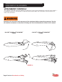
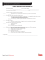
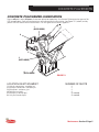
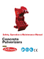
Safety, Operation & Maintenance Manual
Concrete
Pulverizers
Part Number T039705
INTELLECTUAL PROPERTY – PATENT INFORMATION
This product is covered by one or more of the following patents.
U.S. PATENT NUMBERS:
5,474,242
7,240,869
5,531,007
7,487,930
5,992,023
7,578,461
7,322,273
7,832,130
8,146,256
8,104,384
EPO Patent Numbers
435,702
737,107
1,682,299
1,789,225
PREFACE
This manual contains information for the safe and proper operation and maintenance of the concrete
pulverizer. Read the entire manual before the initial start-up of the attachment. It is important to know the
correct operating procedures of the attachment and all safety precautions to prevent the possibility of property
damage and personal injury.
The LaBounty attachment has been designed and manufactured with high quality materials and care
in workmanship. The instructions in this manual have been prepared to ensure that, when followed properly,
the attachment will provide efficient and reliable service. Continuing product development and improvement
may have caused changes in the attachment that are not reflected in this manual. If a question arises regarding
the operation or maintenance of the attachment, contact a LaBounty dealer for the most current information
available.
TABLE OF CONTENTS
Section 1 Introduction
Introduction ................................................................................................................................1-2
Understand Signal Words ...........................................................................................................1-2
Safety Summary .........................................................................................................................1-3
Label Locations...........................................................................................................................1-4
Section 2 About the Attachment
Model Description ..................................................................................................................... 2-2
Features ..................................................................................................................................... 2-2
Concrete Pulverizer Terms ......................................................................................................... 2-3
Concrete Pulverizer Glossary ..................................................................................................... 2-4
Section 3 Installation
Concrete Pulverizer Mounting Instructions ................................................................................3-2
Concrete Pulverizer Removal Instructions ..................................................................................3-5
Concrete Pulverizer Storage .......................................................................................................3-5
Section 4 Operation
Before You Start ..........................................................................................................................4-2
What You’ll Need ........................................................................................................................4-2
First Things First .........................................................................................................................4-3
General Rules for Safe Operation ...............................................................................................4-3
Attachment Controls ..................................................................................................................4-4
Getting the Feel of the Attachment ............................................................................................4-5
Feathering the Controls ..............................................................................................................4-5
Concrete Pulverizer Operating Tips.............................................................................................4-6
Section 5 Maintenance
Maintenance Safety Procedures ..................................................................................................5-2
General Rules for Maintenance ...................................................................................................5-3
Periodic Service Schedule............................................................................................................5-3
Daily Inspection Checklist............................................................................................................5-4
Concrete Pulverizer Lubrication ...................................................................................................5-6
General Guidelines for Build-up and Hardsurfacing .....................................................................5-8
Build-up Recommendations ........................................................................................................5-9
Hardsurfacing Recommendations ...............................................................................................5-9
Tooth Build-up and Hardsurfacing ............................................................................................... 5-10
Attachment Build-up and Hardsurfacing .....................................................................................5-12
Bolt Torque Guidelines ................................................................................................................5-14
Metric Capscrew Size Guide ......................................................................................................5-14
Dry Bolt Torque Charts ................................................................................................................5-14
Swift-Lock Build-up Template Kit Parts Numbers .......................................................................5-15
CONCRETE PULVERIZERS
SECTION 1 INTRODUCTION TO SAFETY
Introduction .................................................................................................................................. 1-2
Understand Signal Words ............................................................................................................. 1-2
Safety Summary ........................................................................................................................... 1-3
Attachment Decals ....................................................................................................................... 1-4
Introduction to Safety Section 1 Page 1
CONCRETE PULVERIZERS
INTRODUCTION
Your safety and the safety of others is a direct result
of how you operate and maintain your equipment.
Read and understand this manual and other safety
information provided with the base machine and be
sure that you understand all controls and operating
instructions before attempting to operate this
equipment. Failure to follow the safety precautions
can result in personal injury, death or property
damage.
Carefully read all safety messages in this manual
and on your equipment safety signs. Keep safety
signs in good condition; replace missing or damaged
safety signs.
Because LaBounty cannot foresee all hazardous
circumstances, the precautions listed in this manual
and on the equipment are not all-inclusive. If a
procedure, method, tool or part is not specifically
recommended by LaBounty, determine whether it is
safe for you and others, and that the equipment will
not be damaged or made unsafe as a result of your
decision to implement it.
The basic rules are summarized in this section of the
manual. They also appear throughout the manual
along with additional specific rules for safety and
operation.
UNDERSTAND SIGNAL
WORDS
When you see the following symbols and signal words
on your equipment or in this manual, be alert to the
potential for personal injury or equipment or property
damage. Follow recommended precautions and safe
operating practices.
Indicates immediate hazards that WILL result in
severe personal injury or death.
Indicates hazards or unsafe practices that CAN
result in severe personal injury or death.
Indicates hazards or unsafe practices that could
result in personal injury.
NOTICE
Indicates notes of importance to a procedure or
part.
Page 2 Section 1 Introduction to Safety
CONCRETE PULVERIZERS
SAFETY SUMMARY
If the attachment is not functioning properly, you
must shut the machine down and follow proper
lockout, tag, and repair procedures.
Ensure that the cab is equipped with the proper
safety guards for LaBounty applications. In addition,
it is required that the cab be equipped with an
approved Falling Object Protection Structure
(FOPS) when processing materials. The FOPS must
meet the requirements of SAE standard J1356. A
transparent shatter-resistant shield covering the
front of the cab is also required. Contact your base
machine equipment dealer or manufacturer for more
information on the availability of FOPS. Lack of
proper FOPS may result in injury or death.
Clear all persons and equipment from the area of
operation and machine movement. NEVER move loads
over people or equipment. When viewing the operation
of the attachment, maintain a safe distance of at least
75 feet (22.9 meters).
NEVER approach power lines with any part of the
machine. Keep clear at a minimum of 15 feet (5
meters).
Avoid tipping. The attachment will alter the lift
capacities of the base machine. DO NOT overload
the excavator or serious injury could result. Lift
capacities will vary if the base machine is not on level
ground. Carry loads in recommended positions for
maximum stability. Use the recommended excavator
counterweight. Use short slings and lift the load only
as high as necessary.
DO NOT process or handle material with the
attachment over the operator’s cab.
DO NOT allow riders on the machine.
DO NOT attempt to shear brittle materials such as axles
and railroad rail. Brittle material breaks or shatters instead
of shearing. The material being processed could become
a projectile and cause injury or death. DO NOT process
any material in any position that may propel it toward
operator, other workers, buildings or equipment.
DO NOT close the attachment on a structure and
reverse the excavator in an attempt to pull down
material.
Introduction to Safety Section 1 Page 3
CONCRETE PULVERIZERS
SAFETY SUMMARY continued
NEVER remove any pins unless the attachment is on
the ground and blocked up or serious injury or death
could result. Metal chips or debris may fly when a
connecting pin is struck. Use a brass drift when striking
pins and always wear protective clothing and proper eye
protection. Pins may fly when struck with force to drive
them in or out. Keep people clear when removing or
installing pins.
NEVER operate equipment without the original
equipment safety guards in place. If the cab glass
is missing or damaged, check with your dealer or
manufacturer for proper replacement.
Under no circumstances should any modifications
be made to LaBounty equipment without factory
authorization.
ALWAYS lower the boom to the ground before
leaving the cab. If it is necessary to work on an
attachment off the ground, securely support the
machine and attachment. DO NOT support the
machine on cinder blocks, hollow tiles, or props that
may crumble under continuous load. DO NOT rely
on a cylinder to hold the attachment in the air. DO
NOT work under a machine that is supported only by
a jack.
DO NOT let hot hydraulic oil get in contact with the
skin as it could cause severe burns. Wear adequate
protective clothing and safety equipment. DO NOT
tamper with any hydraulic line or component while
it is pressurized. Escaping fluid under pressure can
penetrate the skin, causing serious injury. Relieve
pressure before unhooking hydraulic or other lines.
Tighten all connections before applying pressure.
Keep hands and body away from pinholes and nozzles
which eject fluids under high pressure. Use a piece of
cardboard to search for leaks. If ANY fluid is injected
into the skin, seek immediate medical assistance.
Page 4 Section 1 Introduction to Safety
DO NOT weld on any structural member unless
specifically authorized by LaBounty. Any unauthorized
welding or welding procedures may result in personal
injury.
ALWAYS wear close-fitting clothing and safety
equipment appropriate to the job. Safety equipment
should be worn at all times when viewing, operating,
or maintaining the attachment to prevent injury.
Safety equipment includes eye protection, hard hat,
steel toe shoes, gloves, and hearing protection.
Keep clear of all potential pinch points, including
the moving upper jaw, cylinder connections, bucket
linkages or other moving parts.
Before operating the attachment, read and
observe all safety instructions in the Operation
and Maintenance sections of this manual. If you
are unfamiliar with any operation or maintenance
procedure, seek instruction before proceeding.
CONCRETE PULVERIZERS
ATTACHMENT DECALS
STANLEY LABOUNTY BRAND DECALS
(REPLACEMENT DECALS AVAILABLE UPON REQUEST)
FIGURE 1-1
SAFETY FIRST DECAL PART NUMBER 503590
(INCLUDED WITH MANUALS)
FIGURE 1-2
Introduction to Safety Section 1 Page 5
CONCRETE PULVERIZERS
ATTACHMENT DECALS
CONTINUED
GREASE
GREASE DECAL
PART NUMBER 116338
FIGURE 1-3
1538 Highway 2
Two Harbors, MN 55616
tel: 1-800-522-5059
fax: 218-834-3879
www.stanleyhydraulic.com
Made in the U.S.A. with Global Materials
Attachment Model:
Serial Number:
Year of Manufacture:
Weight:
MODEL/SERIAL NUMBER PLATE
PART NUMBER 511045
FIGURE 1-6
SAFE VIEWING DISTANCE DECAL
PART NUMBER 116389
FIGURE 1-4
U.S. PATENT NUMBERS
5,474,242
7,240,869
5,531,007
7,487,930
5,992,023
7,578,461
7,322,273
7,832,130
8,146,256
8,104,384
EPO PATENT NUMBERS
435,702
737,107
1,682,299
1,789,225
STANLEY LABOUNTY
1538 Highway 2
1-800-522-5059
Two Harbors, MN 55616
www.stanleyhydraulic.com
FOREIGN PATENTS AND OTHER PATENTS PENDING
116404
PATENT PLATE
PART NUMBER 116404
FIGURE 1-7
SAFETY DECAL
PART NUMBER 503647
FIGURE 1-5
Page 6 Section 1 Introduction to Safety
CONCRETE PULVERIZERS
SECTION 2 ABOUT THE ATTACHMENT
Model Description ........................................................................................................................ 2-2
Features........................................................................................................................................ 2-2
Concrete Pulverizer Terms ............................................................................................................ 2-3
Concrete Pulverizer Glossary ....................................................................................................... 2-4
About the Attachment Section 2 Page 1
CONCRETE PULVERIZERS
MODEL DESCRIPTION
The LaBounty Concrete Pulverizer (CP) is a simple yet powerful tool that excels at separating rebar and concrete, turning these two waste materials into recyclable, profitable products. It is a quiet alternative to traditional demolition and concrete processing methods, such as hydraulic hammers and wrecking balls.
Concrete Pulverizers are available in sizes for base machines ranging from 25,000 to 160,000 pounds (11,500
to 73,000 kg) and openings from approximately 28 to 54“ (0.7 to 1.4 meters).
The LaBounty Concrete Pulverizer mounts in place of the excavator bucket. The bucket cylinder and linkage
provide the crushing force—no additional circuits are required. Each CP is designed to get maximum power
and productivity from the excavator. Depending on the mounting option of your CP, it may be possible to
mount it on other excavator makes and models within the same weight class by installing a new mounting
kit. Conctact your LaBounty representative with the serial number to evaluate other mounting options for
your CP.
Concrete Pulverizers include LaBounty’s patented Swift-Lock pin-on replaceable teeth. These teeth offer long
wear, impact resistance, and simple maintenance. Each tooth segment is secured to the jaw with one pin
making it possible to replace a complete set of teeth in as little as a half an hour.
FEATURES
• Patented Swift-Lock pin-on replaceable teeth offer
fast and easy maintenance as well as long wear and
impact resistance.
• Made with high-strength, abrasion-resistant steel for
durability.
• Multimachine mounting is possible among some
excavator models within the same weight class.
• Mounting pad may also be used with LaBounty
Grapples, BLS Shears, and MWS Wood Shears.
• Installs in as little as 30 minutes.
• At-factory upgrading and rebuilding services available for extended life.
FIGURE 2-1
Page 2 Section 2 About the Attachment
CONCRETE PULVERIZERS
ATTACHMENT TERMS
UPPER JAW
(MOVEABLE)
MAIN PIVOT & MAIN PIN
LOWER JAW
(STATIONARY)
EXCAVATOR STICK
BUCKET CYLINDER
POWER LINK
LINK PIN
SWIFT-LOCK TEETH
AND TOOTH SEATS
MOUNTING PAD
GUIDE LINK
POSITION ARM
FIGURE 1-5
About the Attachment Section 2 Page 3
CONCRETE PULVERIZERS
ATTACHMENT GLOSSARY
Build-up
Welding process where worn off parent material is replaced with new metal. A very important maintenance
procedure to extend the life of the pulverizer.
Guide Link
Part of the excavator bucket linkage that pins at one end to the excavator stick and pins at the other end to the
bucket cylinder and the power link.
Hardsurface
Welding process to protect the parent material of the pulverizer. The hardsurface acts as a wear surface.
Link Pin
The pin that connects the upper jaw of the pulverizer that is held stationary by the position arm.
Lower Jaw
The lower half of the pulverizer that is held stationary by the position arm.
Main Pin
The pin that connects the upper and lower jaws to the excavator stick tip. The main pin is a component of the main
pivot group.
Mounting Pad
A bracket welded to the bottom of the excavator stick at a specific location. The position arm pins between the
mounting pad and the pulverizer to hold the lower jaw stationary. The mounting pad properly positions the lower
jaw and distributes stresses evenly through the stick during operation.
Position Arm
A structural member pinned between the lower jaw and mounting pad to support the lower jaw and hold it
stationary.
Power Link
Part of the excavator bucket linkage that pins at one end to the upper jaw of the pulverizer and pins at the other
end to the guide link and bucket cylinder.
Spool
A flanged tube that holds the two jaws together and creates a pivot for the upper jaw. There are two spools in the
main pivot of a pulverizer.
Swift-Lock
Teeth
Easily replaceable, pin-on wear parts on the upper and lower jaws for pulverizing concrete. Each tooth fastens to
its tooth seat with a pin and retainer ring.
Thrust
Washers
Wear components in the main pivot between the upper and lower jaws that act as a wear surface between the jaws
as they pivot.
Tooth Pins &
The hardware that fastens each tooth to its seat. The tooth pin is held in place by the retainer ring.
Retainer Rings
Tooth Seats
Receptacles that are welded in place on the upper and lower jaws. Each Swift-Lock tooth attaches to its seat
with a single pin and retainer.
Upper Jaw
The upper half of the pulverizer that is connected to the bucket linkage of the excavator. It pivots against the lower,
stationary jaw to crush concrete.
Page 4 Section 2 About the Attachment
CONCRETE PULVERIZERS
SECTION 3 INSTALLATION
Concrete Pulverizer Mounting Instructions .................................................................................. 2-2
Concrete Pulverizer Removal ....................................................................................................... 2-5
Concrete Pulverizer Storage ......................................................................................................... 2-5
Installation Section 3 Page 1
CONCRETE PULVERIZERS
CONCRETE PULVERIZER MOUNTING INSTRUCTIONS
It is recommended that the mounting bracket not be welded to the excavator stick until the pulverizer is
installed. Mount the attachment as follows:
1. Postion the pulverizer on a flat, level surface as shown in figure 3-1. Remove the main pin and link pin.
2. With all personnel standing clear, walk the excavator into position and line up the excavator stick tip with the
main pivot of the pulverizer as shown in figure 3-1.
3. Install the main pin through the main pivot of the CP and the stick tip of the excavator. Make sure to install
the spacers on each side of the stick tip as you slide the main pin through the main pivot.
4. Install the washer and slotted nut on the threaded end of the main pin. Turn the slotted
nut until it is snug against the washer and the spool head. Tighten the nut further until the
next available slot line sup with the hole in the main pin. Install the cotter pin (see figure 3-2).
FIGURE 3-1
Page 2 Section 3 Installation
CONCRETE PULVERIZERS
CONCRETE PULVERIZER MOUNTING INSTRUCTIONS continued
SPOOL HEAD
MAIN PIN
(THREADED END)
WASHER
SLOTTED NUT
COTTER PIN
FIGURE 3-2
5. Extend the bucket cylinder and line up the power link with the linkage connection of the pulverizer. Install the
link pin. Place the collar on the end of the link pin and secure it with the bolt and nut provided.
6. With all personnel standing clear, curl the excavator stick and extend the bucket cylinder to position the lower
jaw as shown in figure 3-3.
FIGURE 3-3
7. Place the mounting pad on the bottom of the excavator stick. Connect the position arm to the lower jaw of
the puliverizer. Make sure the position arm grease fittings will be accessible.
8. Connect the position arm to the mounting bracket at the center hole.
9. Position the mounting pad along the bottom of the stick to obtain the proper distance from the main pin to
the center hole of the mounting pad. This distance is shown in the Parts Catalog.
Installation Section 3 Page 3
CONCRETE PULVERIZERS
CONCRETE PULVERIZER MOUNTING INSTRUCTIONS continued
10. Weld the pad in position using E7018 low hydrogen welding rod. Make 1/2" (12.7 mm) fillet welds, 3" (78
mm) long, 6" ((150 mm) on center (see figure 3-4). Run out welds 1-1/2" (40 mm) on ends and grind to taper in
both the side view as shown in figure 3-5 and in the top view figure 306.
NOTICE
Under no circumstances should the mounting pad be welded around the ends (see figure 3-4).
NOTICE
If the pulverizer is equipped with a custom mounting pad, refer to the Parts Catalog for special mounting
instructions.
6.00
(150 MM)
FIGURE 3-4
DO NOT WELD
AROUND ENDS
SIDE VIEW WELD DETAILS
FIGURE 3-5
Page 4 Section 3 Installation
1.50
(40 MM)
3.00
(75 MM)
RUN OUT WELDS, GRIND
WELD TO TAPER SEE
WELD DETAILS
TOP VIEW WELD DETAILS
FIGURE 3-6
CONCRETE PULVERIZERS
CONCRETE PULVERIZER REMOVAL
1. Fully close the pulverizer and place it on a solid, level surface in the position shown in figure 3-7.
2. Support the position arm while removing the pin from the mounting pad then lower the position arm to the
ground.
3. Remove the pin from linkage connection.
4. Remove the pin from the main pivot. With all personnel standing clear, carefully raise the excavator stick
away from the puliverizer.
FIGURE 3-7
CONCRETE PULVERIZER STORAGE
1. Place the attachment on a solid, level surface.
2. Apply a coating of grease to the bores, pins, and any other exposed, unpainted surface.
3. Replace all pins in their bores to prevent misplacing them.
4. Grease at all locations (refer to the lubrication instructions in the maintenance section of this manual).
Installation Section 3 Page 5
CONCRETE PULVERIZERS
Page 6 Section 3 Installation
CONCRETE PULVERIZERS
SECTION 4 OPERATION
Before You Start ............................................................................................................................ 4-2
What You’ll Need .......................................................................................................................... 4-2
First Things First ........................................................................................................................... 4-3
General Rules for Safe Operation ................................................................................................. 4-3
Attachment Controls .................................................................................................................... 4-4
Getting the Feel of the Attachment ............................................................................................. 4-5
Feathering the Controls ................................................................................................................ 4-5
Concrete Pulverizer Operating Tips .............................................................................................. 4-6
Introduction to Safety Section 4 Page 1
CONCRETE PULVERIZERS
BEFORE YOU START
KNOW YOUR SAFETY PROGRAM
1. Read and understand the safety section of this
manual and the base machine manual.
2. Know the employer’s safety rules for your job.
Consult your foreman for specific instructions and
safety equipment required.
3. Learn the traffic rules at the work site.
4. Know the hand signals used on the job and who is
responsible for signaling. Take signals from only ONE
person.
KNOW YOUR EQUIPMENT
• Learn the location and function of all controls.
Test all controls to ensure proper operation. If any
malfunctions are found, shut the machine down and
report the malfunction for repair.
• Be familiar with the safety devices on the machine,
indicators, warning devices and caution instructions.
They will alert you to conditions that may make it
hazardous to continue operating.
• Wear proper protective clothing including hard
hat, safety shoes, ear protectors, reflective clothing,
safety goggles and work gloves. Loose clothing
can get caught in machinery and cause injury.
Wrist watches, rings and other accessories can be
dangerous, as well.
• Know the clearances in the work area.
Page 2 Section 4 Introduction to Safety
FIRST THINGS FIRST
1. Ensure all safe viewing distance decals are
installed and legible; contact LaBounty for
replacements as required.
2. Have a DAILY Safety Dialog with all those with
whom you work. Inform them of any out-of-theordinary work that may be planned for the day.
Remind them of the safe working distance.
3. Clear the area; inspect. ALWAYS look out for
others. In any work area, people constitute a serious
safety hazard. Before operating, walk completely
around the machine to be sure there are no workers
next to, under or on it. Warn nearby workers that you
are starting up; DO NOT start up until they are out of
danger.
4. Each day before starting, visually inspect the
machine by walking around it entirely; check the
location of cables, gas lines, and water mains before
any operations. Make sure work site footing has
sufficient strength to firmly support the machine.
When working close to an excavation, position
machine with the propel motors at the rear.
5. Once started, keep bystanders clear, especially
before moving the boom, swinging the upper
structure, or traveling. ALWAYS be alert for
bystanders in or near the operating area.
SAFETY DEVICES YOU’LL
NEED
Seat belts
Canopies
Falling Objects Protective Structures (FOPS)
Shields and guards
Safety decals
Visual or audible warning devices
Flags and flares
Barricades
Signs and other markings
Warning lights
CONCRETE PULVERIZERS
GENERAL RULES FOR SAFE
OPERATION
1. Read the Operator’s Manual for the excavator
that the grapple is on. Know the control levers and
their functions. Also note ALL safety devices on the
machine and ensure that they are working properly.
2. KNOW the capacity of the excavator and its
attachments. DO NOT overload the machine or
serious injury could result.
3. It is required that a Falling Objects Protection
Structure be installed surrounding the excavator cab
for all material handling applications.
4. DO NOT use attachment for anything except
what it is intended for or warranty will be voided.
5. DO NOT operate a poorly maintained or damaged
attachment.
6. ALWAYS maintain a safe operating distance
between any material suspended and held by the
attachment and the cab of the machine.
7. NEVER leave a load suspended in the air, pass
it over people, occupied vehicles or buildings or
serious injury could result.
8. ALWAYS keep a watchful eye on exposed parts,
such as the position arm, so as to not damage them
when working in confined spaces.
9. ALWAYS maintain at least 15 feet (5 meters)
between the attachment and any nearby power lines
or serious injury could occur.
10. When leaving the machine for any reason,
ALWAYS lower the attachment to the ground.
11. DO NOT close the attachment on a structure
and reverse the excavator in an attempt to pull down
material.
12. AVOID collision of the boom or attachment,
especially when working with limited visibility or
inside buildings. Know the height and reach of the
processor during operation, travel and swinging
upper structure.
13. AVOID contacting machine with the attachment
or any material held by it.
14. Use machine swing for positioning only. DO NOT
use the attachment as a jack hammer or wrecking
ball.
15. AVOID contact between boom arm or
attachment and overhead obstacles when you
operate, move or haul the machine.
16. The attachment is not a dozer. DO NOT position
it on the ground and travel forward.
Determine the control for each movement of the
excavator before attempting to operate. Practice
the machine movements as described in “Getting
the Feel of the Attachment” on page 4-6.
Introduction to Safety Section 4 Page 3
CONCRETE PULVERIZERS
ATTACHMENT CONTROLS
The LaBounty concrete pulverizer replaces the bucket of an excavator and operates with the same controls—
no additional hydraulics are required. The bucket dump control opens the attachment and the bucket curl
closes the attachment.
Determine the control for each movement of the attachment before attempting to operate. Practice
the machine movements as described in Getting the Feel of the Attachment section of this manual.
BUCKET DUMP=ATTACHMENT
OPEN
BUCKET CURL=ATTACHMENT
CLOSE
FIGURE 4-1
Page 4 Section 4 Introduction to Safety
CONCRETE PULVERIZERS
GETTING THE FEEL OF THE
ATTACHMENT
Every operating part of any machine has a slightly
different “operating feel”—an individual machine
response to the movement of the controls. Before
starting the first job with a new machine, it is
suggested that the operator find an open spot on
firm, level ground safely away from other people
that’s free of obstructions such as trees, buildings
and other equipment. Move the machine to this
area – and spend some time just getting to know the
“operating feel” of the machine and the attachment
(see figure 4-2).
Feathering the controls is a technique that will
increase output and make operating the attachment
easier. When starting any motion of the machine,
move the control slightly from neutral until it starts
to move then smoothly move the control to increase
motion to desired speed. Do the same when
stopping a motion.
This “get acquainted” time will allow the operator
to become familiar with the control levers and
attachment before beginning work.
The machine is exceedingly powerful. Do not
operate carelessly; there is potential for personal
injury and equipment damage. Be concerned about
safety when preparing to operate the new machine.
Ensure safe operation by inspecting the machine
as explained in the Getting Started Safely section
earlier in this chapter. This inspection amounts to a
common sense visual check of the machine at the
beginning of every operation. Follow a preventive
maintenance program to reduce the possibility of
costly downtime.
FEATHERING THE CONTROLS
The “fluid” nature of hydraulic power requires a
special operating approach to the attachment that
can be described as a smooth, even technique.
The control levers should be moved in a gradual,
deliberate way rather than with jerky, abrupt
movements. Jerky operation can cause damage and
early wear to various parts on the machine, and can
also overheat the hydraulic system. For example,
as each control lever is moved forward or backward
from the center (or neutral) position, the oil flows
to the cylinder or motor controlling a function. The
component (boom, attachment, etc.) starts to move.
The component moves faster as the control lever
is moved further forward or backward. Holding the
lever in the forward or backward position will hold
that movement at a given rate of speed. To slow the
movement down, gradually move the lever toward
the neutral position. Movement is stopped at the
neutral position. The position is maintained until the
control lever is moved again.
FIGURE 4-2
Introduction to Safety Section 4 Page 5
CONCRETE PULVERIZERS
CONCRETE PULVERIZER OPERATING TIPS
1. To get the most crushing force from the pulverizer, pin the position arm in a mounting pad hole that allows
the guide link to travel beyond 90º to the bucket cylinder before crushing begins (see figure 4-3).
GUIDE LINK
90º
RANGE OF GREATEST
PULVERIZING FORCE 90º
TO CLOSE
FIGURE 4-3
2. When processing large, heavy materials, open and close with short cycles rather than attempt to crush
the material in one cycle (see figure 4-4). This allows the pulverizer to downsize the material until it is able to
pulverize it completely. This technique creates less stress on the attachment and excavator hydraulics.
OPEN AND CLOSE ON
HEAVY MATERIAL
FIGURE 4-4
Page 6 Section 4 Introduction to Safety
CONCRETE PULVERIZERS
CONCRETE PULVERIZER OPERATING TIPS
continued
3. The mounting pad of the LaBounty Concrete Pulverizer has three pin positions. By using the different
positions, the angle of the lower (stationary) jaw can be adjusted (see figure 4-5). For each job, the lower jaw
can be positioned to make the CP more productive or easier to use. Some experimentation may be necessary
to learn the advantages of each position. Using the front position provides the least amount of total opening
while the rear position provides the most. The center position is the best for general use.
MOUNTING PAD
FRONT POSITION
REAR
CENTER POSITION
FRONT
CENTER
REAR POSITION
FIGURE 4-5
Introduction to Safety Section 4 Page 7
CONCRETE PULVERIZERS
SECTION 5 MAINTENANCE
Maintenance Safety Procedures ....................................................................................................5-2
General Rules for Maintenance ......................................................................................................5-3
Periodic Service Schedule ..............................................................................................................5-3
Daily Inspection Checklist ..............................................................................................................5-4
Concrete Pulverizer Lubrication......................................................................................................5-6
General Guidelines for Build-up and Hardsurfacing........................................................................5-8
Build-up Recommendations ...........................................................................................................5-9
Hardsurfacing Recommendations ..................................................................................................5 - 9
Tooth Build-up and Hardsurfacing .................................................................................................5-10
Attachment Build-up and Hardsurfacing .......................................................................................5-12
Bolt Torque Guidelines ...................................................................................................................5-14
Metric Capscrew Size Guide .........................................................................................................5-14
Dry Bolt Torque Charts...................................................................................................................5-14
Swift-Lock Build-up Template Kit Parts Numbers ..........................................................................5-15
Maintenance Section 5 Page 1
CONCRETE PULVERIZERS
MAINTENANCE SAFETY
PROCEDURES
Before attempting any maintenance procedure, read
the entire Safety Manual carefully. If any question
arises regarding a safety or maintenance procedure,
contact your LaBounty dealer. For the nearest
LaBounty dealer, see the Contact Information at the
front of this manual.
During maintenance of the shear, it is imperative
that the excavator is turned OFF to prevent injury.
• Inspect the attachment daily. DO NOT operate a
poorly maintained or damaged attachment or major
structural damage could result.
• ALWAYS lower the boom to the ground before
leaving the cab. If it is necessary to work on an
attachment off the ground, securely support the
base machine and attachment. DO NOT support the
machine on cinder blocks, hollow tiles, or props that
may crumble under continuous load. DO NOT rely
on the cylinder to hold the attachment in the air. If a
control is moved or hydraulic pressure is otherwise
released, the attachment will drop. DO NOT work
under a machine that is supported solely by a jack.
• DO NOT attempt to alter or change the physical,
mechanical or hydraulic operation of the attachment
during the warranty period without first consulting
Stanley LaBounty as this could invalidate the
Manufacturer’s Warranty.
• NEVER operate the machine if an unsafe condition
exists. Attach a “DO NOT OPERATE” tag to the
machine.
• If more than one person is working on a machine,
each must be familiar with the controls and aware
of what the others are doing. Before working on a
machine, BE SURE TO TAG THE CONTROLS SO
NO ONE ELSE WILL START IT.
• ALWAYS use two people when making checks
with the engine running – the operator at the
controls must be able to see the person doing the
checking.
• Keep hands away from moving parts. NEVER
lubricate or work on a machine while it is moving.
• ALWAYS wear proper safety equipment when
maintaining the attachment including safety glasses
with side shields, hard hat, steel toe shoes, gloves,
and hearing protection.
• Be sure you understand a service procedure
before working on the machine. DO NOT ATTEMPT
REPAIRS YOU DO NOT UNDERSTAND. ASK FOR
HELP BEFORE STARTING IF YOU ARE UNSURE.
Inferior parts can fail and cause equipment
damage or personal injury.
Page 2 Section 5 Maintenance
GENERAL RULES FOR
MAINTENANCE
1. Read the maintenance manual. Be sure all
maintenance personnel read and understand all
maintenance procedures before they are attempted.
2. Use factory approved parts. Use of parts that
are not factory approved may cause damage
or unnecessary downtime and may void the
attachment warranty.
3. Lubricate daily; follow the lubrications schedule as
outlined on page 5-5.
4. Use the included Inspection Checklist during
inspections to make sure all maintenance is
complete.
5. In extremely cold temperatures, work the
attachment on lighter materials first before working
up to heavier materials. This allows the attachment
and jaws to warm up and makes them less
susceptible to damage.
6. DO NOT weld on the excavator boom or stick
without first consulting your dealer.
7. DO NOT exceed bolt torque specifications (see
the Dry Bolt Torque Chart in this manual).
8. DO NOT disconnect hydraulic hoses or fittings
without first relieving machine hydraulic pressure.
9. DO NOT exert the weight of the excavator on the
shear in order to free the upper shear if it becomes
jammed. Please consult the factory. Jamming
is the result of poor maintenance or improper
operational techniques.
10. DO NOT let hot hydraulic fluid get in contact
with the skin as it could cause severe burns.
11. DO NOT use substitute parts unless you know
that they are the identical to original factory parts in
all characteristics.
12. Refer to the Parts Catalog for your attachment
for LaBounty replacement part numbers. Be sure to
reference the attachment model and serial number
when ordering.
CONCRETE PULVERIZERS
PERIODIC SERVICE
SCHEDULE
SERVICE THE ATTACHMENT AT
SPECIFIED INTERVALS
Inspect, lubricate, make service checks and
adjustments according to the Daily Inspection
Checklist reproduced from this manual. A program
of regular service should be established, using
the machine hour meter to determine when the
attachment should be serviced. Use the intervals
on the Service Schedule when operating in normal
conditions. Service the attachment at shorter
intervals when operating in extreme environmental
or abrasive conditions. Use correct lubricants
and bolt torques. Refer to the lubrication and bolt
torque instructions in this manual when performing
maintenance on the attachment.
DAILY SERVICE REQUIRED
Bolts: Check for looseness or damage.
Retorque if necessary. Refer to Bolt Torque tables
in this manual. Bolts may be retorqued once, then
must be replaced.
Connecting Pins and Pin Retaining Bolts: Inspect
for looseness, damage and/or wear on main pivot
pin and linkage pin. Check pinheads
and pinstops.
Grease Fittings: Lubricate according to the
instructions in this section. Replace broken fittings.
Swift Lock Teeth and Tooth Seats: Make sure all
tooth pins are in place. Inspect for wear indicating
build-up or hardsurfacing is required. Rotate
or replace if necessary. Refer to page 5-6 for
instructions.
Maintenance Section 5 Page 3
CONCRETE PULVERIZERS
DAILY INSPECTION CHECKLIST
Attachment Model _____________________Excavator Hour Meter________________________
Attachment Serial Number ______________________________ Date______________________
_______ 1. Visually inspect attachment for any damage.
_______ a. Check for cracks or excessive wear that may cause structural failure
_______ 2. Inspect the Swift-Lock teeth and tooth seats.
_______ a. Check for excessive looseness or damage. It is acceptable for the teeth to move
slightly from side to side on on their seats
_______ b. Check the tooth pins for damage or looseness
_______ c. If necessary, rework or replace the teeth as outlined in this manual
_______ 3. Inspect all bolts.
_______ a. Visually inspect all bolts and replace any that are loose or damaged
_______ 4. Inspect pins and pin retaining hardware.
_______ a. Main pivot pin
_______ b. Link pin
_______ c. Position arm pins (both ends)
_______ 5. Grease all points until excess appears. Use premium grease no. 2EP or equivalent.
_______ a. Link pin connection in upper jaw lugs
_______ b. Main pin connection in upper jaw lugs
_______ c. Main pivot in stationary jaw
_______ d. Position arm ends
_______ e. End of link pin and main (if required)
_______ f. Check excavator for grease fittings at other connections
Inspected by: __________________________________________________________________________
Page 4 Section 5 Maintenance
CONCRETE PULVERIZERS
CONCRETE PULIVERIZER LUBRICATION
Grease all points every 4 hours of concrete pulverizer operation. Use Amoco Rykon premium grease No.
2EP or equivalent. Grease fitting locations are indicated on the illustration (see figure 5-1, below) and by
yellow GREASE decals on the attachment. Fill with grease until excess appears.
1
(BOTH SIDES)
6
5
4
3
(BOTH SIDES)
2
(BOTH SIDES)
FIGURE 5-1
LOCATION ON ATTACHMENT
1. Link pin connection - movable jaw
2. Main pin connection - movable jaw
3. Main pivot - stationary jaw
4. Position arm ends
5. Main pin (in end of pin)
6. Link pin (in end of pin)
NUMBER OF SHOTS
2
2
2
2
(if needed)
(if needed)
Maintenance Section 5 Page 5
CONCRETE PULVERIZERS
SWIFT-LOCK TOOTH
REPLACEMENT
When the teeth are badly worn or crushing
performance is decreased, the teeth should be
replaced. Depending on the type of concrete being
processed, the interval between teeth changes will
vary. It is recommended that the teeth be replaced
as a set for even wear and the best performance.
Safety equipment should be worn at all times
when maintaining the attachment to prevent
injury. Safety equipment includes eye protection,
hard hat, steel toe shoes, leather gloves, hearing
protection, etc.
1. To change the teeth on the upper jaw, curl the
attachment under and set it down on a firm and level
surface with the jaws open (figure 5-2). Turn the base
machine off. Make sure that the attachment and
jaws are stable and will not drop or close. Block up if
necessary.
2. Work only on the upper jaw with the pulverizer in
this position (figure 5-2). With the teeth facing up,
their weight will be properly supported when the
pins are removed.
FIGURE 5-2
RECEPTACLE
Each tooth is very heavy. Removing a tooth pin
when the tooth is not supported will cause the
tooth to fall and could cause serious injury.
RETAINER
RING & SEAT
3. Use a soft metal drift (such as brass) and a mallet
to drive out the tooth pins (figure 5-3).
4. If the tooth is loose on its seat, lift and slide it out.
If necessary, use a pry bar to loosen the tooth from
the seat. Do not lose the retainer ring.
TOOTH
TOOTH PIN
FIGURE 5-3
Page 6 Section 5 Maintenance
CONCRETE PULVERIZERS
SWIFT-LOCK TOOTH
REPLACEMENT continued
5. Insert the new tooth by sliding it into the slot in
the seat. Make sure the retainer ring is located in its
pocket in the tooth seat before installing the tooth
(figure 5-3 on page 6).
6. Use a mallet to insert the pin through the holes in
the tooth and seat. Be sure to install the pin so the
groove in the pin will line up with the retainer ring
inside the tooth seat. The retainer ring should seat in
the pin groove.
7. Repeat this process for the other worn teeth on
that jaw.
8. When this jaw is done, start up the base machine.
With all personnel standing at a safe distance, lift the
attachment and put it out in front of the excavator
(figure 5-4). Set the attachment back down on the
ground and make sure it will not drop or close.
9. Follow steps 3 through 7 to replace the teeth on
this jaw.
FIGURE 5-4
Maintenance Section 5 Page 7
CONCRETE PULVERIZERS
GENERAL GUIDELINES FOR BUILD UP AND HARDSURFACING
The steel used in LaBounty attachments is stronger and more durable than ever. However, this steel requires
special attention during maintenance. Pay particular attention to the preheat and post-heat instructions and
follow them exactly. Review the following guidelines for build-up and hardsurfacing the attachment—detailed
instructions on maintaining specific areas of the attachment are on the following pages. Contact your Stanley
LaBounty dealer or the Stanley LaBounty Service department for further information.
PREHEAT
Preheat the general surrounding area to at least 200°F (100°C) to remove moisture from the base material.
Before ANY thermal process is applied to the concrete pulverizer steel, including welding, tack welding, torch
cutting, and air-arcing, preheat the area within 6" (150 mm) of the local area to a minimum of 400°F (200°C)
and a maximum of 450°F (230°C). Preheat must be uniform throughout the material thickness and maintained
until all welding has been completed. Avoid cyclic heating and large temperature swings. Preheating may be
done by localized gas torches or thermal strip blankets.
POST HEAT
If preheat has dropped below 400°F (200°C) within 6" (150 mm) of the weld area, post heat to 400° (200°C)
and wrap with heat blanket to allow it to cool slowly to the ambient temperature. Plan to perform build-up and
hardsurfacing at the end of the day or when there will be adequate time for the welded areas to cool before
putting the attachment back into service.
HANDLING AND STORAGE OF WELD MATERIALS
Follow the weld manufacturer’s handling and storage instructions closely. Make sure the electrodes or wire
are free of moisture. Moisture can cause cracks and porosity in the weld and possibly the base metal beneath
the weld.
WELD QUALITY
Quality and attention to detail in welding can significantly affect the life of the attachment. Stanley LaBounty
strongly recommends that only qualified and certified welders perform this work. Make sure the weld consumables and base material are clean, dry, and free of grease, paint, dirt, or any other foreign substance that
may harm the weld.
NOTICE
Preheat and post-heat instructions must be followed
exactly. Failure to do so can compromise warranty
coverage.
Page 8 Section 5 Maintenance
CONCRETE PULVERIZERS
BUILD UP
RECOMMENDATIONS
Refer to the list of AWS classifications below to
select a suitable build-up material for LaBounty
concrete pulverizers. Weld products within these
classifications meet the combined requirements for
strength, toughness, and ductility that are essential
for LaBounty applications.
Shielded Metal Arc Welding - Stick Electrodes
E7018
E8018-C3
Gas Metal Arc Welding - Solid Wire Electrodes
ER70S-6
Gas Metal Arc Welding - Flux Cored Electrodes
E71T-1
E71T-1M
E80T1-Ni1
E80T1-Ni1M
Gas Metal Arc Welding - Metal Powder Cored
Electrodes
E70C-6M
E80C-Ni1
Welding suppliers can assist in identifying products
that meet these AWS classifications.
HARDSURFACING
RECOMMENDATIONS
For hardsurfacing, Stanley LaBounty recommends
Amalloy 814H rod or equivalent. It is important to
always use a hardsurfacing weld material with a
chromium content of less than 10% and a severe
impact-resistance rating to prevent cracking.
If in doubt about what hardsurface material to use,
please contact the Stanley LaBounty Customer
Service Department. Failure to adhere to LaBounty
hardsurfacing recommendations may compromise
the attachment warranty.
Hardsurfacing should be applied directly on top of
the build-up welds. The build-up acts as a bonding or
underlayment for the hardsurfacing. This reduces the
chances that the hardsurfacing will crack.
Contact Information for Amalloy Welding and Industrial Supply:
Phone: 800-735-3040 (toll free)
Fax: 623-792-8706
Website: www.amalloy.com
NOTICE
Using improper build-up and hardsurfacing products
may result in premature wear or increased potential
for cracking and may compromise warranty coverage.
NOTICE
Do not use stainless hardsurface rod. It is too brittle
for LaBounty applications and has a tendency to
crack, weakening the base metal.
Maintenance Section 5 Page 9
CONCRETE PULVERIZERS
TOOTH BUILD-UP
AND HARDSURFACING
See the table on page 5-15 for the part numbers for
Swift-Lock build-up templates. If desired, Swift-Lock
Teeth can be built up and hardsurfaced to increase
their life. Depending on the situation, it may be more
cost-effective to replace the teeth when they become worn rather than build them up. Build-up and
hardsurface the teeth when there will be adequate
time for them to cool slowly before they are put back
into service. Use the following process to build up
and hardsurface the teeth.
1. Clean all dirt and grease from the areas to be built
up. If any old hardsurfacing still exists, remove it
down to the base metal by grinding.
2. Place the build-up template along the tooth to determine the amount of build-up required (figure 4-5).
Build-up templates can be ordered from LaBounty.
3. Preheat the tooth to about 200ºF (100ºC) to
remove moisture. Preheat the area to be built up
to 300-400ºF (150-200ºC). DO NOT exceed 450ºF
(230ºC). Use a temperature stick to test the area
frequently, because overheating can harm the tooth.
Temperature sticks are available from LaBounty.
4. Using AWS E7018 welding rod or equivalent,
make side-by-side passes down the face of the cutting edge until the area is covered. Stress relieve and
remove slag after each pass by peening vigorously.
Continue to do this until the profile of the tooth
matches the template as closely as possible. Grind
the edges square to match the template profile.
NOTICE
Check the temperature often during this procedure
to maintain 300-400ºF (150-200ºC). Do not exceed
450ºF (230ºC).
Page 10 Section 5 Maintenance
BUILD-UP TEMPLATE
FIGURE 5-5
• Remove paint before welding or heating.
Hazardous fumes can be generated when paint is
heated.
• When sanding or grinding paint, do not breathe
the dust. Wear an approved respirator.
• If you use solvent or paint stripper, remove the
stripper with soap and water before welding.
• Remove solvent or paint stripper containers and
other flammable material from the area.
• Have a fire extinguisher nearby during all cutting
and welding operations. Clean areas to be cut or
welded of oil and flammable materials. Protect all
flammable areas from sparks.
• Do all work in a well ventilated area. Dispose of
paint and solvent properly.
CONCRETE PULVERIZERS
TOOTH BUILD-UP
AND HARDSURFACING
continued
5. Start hardsurfacing the tooth by applying parallel passes of AWS E7018 build-up running the length of the
tooth (figure 5-6). These single passes should be 1/2" (13 mm) apart and will serve as an underlayment for the
hardsurface rod.
NOTICE
DO NOT apply the hardsurface directly to the parent material.
6. Apply a bead of Amalloy 814H rod or equivalent directly on top of each of the underlayment beads. It is important to use an air-operated slag peener on each pass of weld to relieve stress.
7. Taper the ends of each hardsurface bead by grinding in line with the cutting edges. Do not undercut the weld
with the grinder.
8. When welding and grinding is complete, peen the welded area until it is shiny or until your peener cannot dent
the weld anymore (typically five to ten minutes). This will harden the welded area.
9. When finished, be sure to cover the reworked teeth with a heat blanket to allow them to cool slowly.
HARDSURFACE BEADS
0.50” (13 MM)
FIGURE 5-6
Maintenance Section 5 Page 11
CONCRETE PULVERIZERS
ATTACHMENT BUILD UP
AND
HARDSURFACING
If desired, additional areas of the lower and upper
jaws may be built up and hardsurfaced to increase
their life. Stanley LaBounty recommends that only
certain areas of the attachment be hardsurfaced.
Hardsurfacing applied to non-approved areas can
cause serious damage to the attachment and limit
its performance. See figure 5-7 for approved surfaces. Hardsurface these areas only when there will be
adequate time for them to cool slowly before they
are put back into service. Use the following process
to build-up and hardsurface the desired area.
1. Clean all dirt and grease from the areas to be built
up. If any old hardsurfacing still exists, remove it
down to the base metal by grinding.
2. Preheat the area to approximately 200ºF (100ºC)
to remove moisture then heat the area to be built
up to 300-400ºF (150-200ºC). Do not exceed 450ºF
(230ºC). Use a temperature stick to test the area
frequently to avoid overheating and damaging the
attachment. Temperature sticks are available from
Stanley LaBounty.
3. Using AWS E7018 welding rod or equivalent, make
side-by-side passes until the area is covered. Stress
relieve and remove slag after each pass by peening
vigorously. Continue to do this until the profile of the
area matches the template.
• Remove paint before welding or heating.
Hazardous fumes can be generated when paint is
heated.
• When sanding or grinding paint, do not breathe
the dust. Wear an approved respirator.
• If you use solvent or paint stripper, remove the
stripper with soap and water before welding.
• Remove solvent or paint stripper containers and
other flammable material from the area.
• Have a fire extinguisher nearby during all cutting
and welding operations. Clean areas to be cut or
welded of oil and flammable materials. Protect all
flammable areas from sparks.
• Do all work in a well ventilated area. Dispose of
paint and solvent properly.
NOTICE
Check the temperature often during this procedure
to maintain 300-400ºF (150-200ºC). Do not exceed
450ºF (230ºC).
FIGURE 5-7
Page 12 Section 5 Maintenance
CONCRETE PULVERIZERS
ATTACHMENT BUILD-UP AND
HARDSURFACING (CONTINUED)
4. Apply a bead of Amalloy 814H rod or equivalent directly
on top of each of the underlayment beads to create a 45º
cross-hatch or “diamond” pattern on the approved surfaces of the attachment. Space the beads approximately
1½ to 2" apart. It is important to use an air-operated slag
peener on each pass of weld to relieve stress.
5. Taper the ends of each hardsurface bead by grinding
in line with the cutting edges. Do not undercut the weld
with the grinder.
6. When welding and grinding is complete, peen the
welded area until it is shiny or until the peener cannot
dent the weld anymore (typically 5 to 10 minutes). This
will harden the welded area.
7. When finished, be sure to cover the reworked teeth
area with a heat blanket to allow it to cool slowly.
DETAIL A
(UPPER JAW SIMILAR)
FIGURE 4-8
BASE PLATE
(BOTH SIDES)
DETAIL B
(UPPER JAW SIMILAR)
BLADE SEATS
(BOTH SIDES)
OUTER TINES
Maintenance Section 5 Page 13
CONCRETE PULVERIZERS
BOLT TORQUING GUIDELINES
Proper bolt installation is critical to ensure the safe and efficient operation of the attachment and jaw set.
Carefully follow the steps below to properly install bolts.
1. Always replace bolts and nuts with the same size and class of fastener. Replacement fasteners can be
ordered from the LaBounty Parts Department to ensure the correct part is used. Unless otherwise specified, use class 10.9 metric hex head capscrews, class 10.9 metric flat head capscrews, and class 12.9 metric
socket head capscrews.
2. Make sure bolts, nuts and bolt holes are free of dirt, oil, grease and other contaminants.
3. If necessary, use the Capscrew Size Guide, below, to determine the size of the bolt being installed.
4. Use the Dry Bolt Torque Chart, below, to find the proper torque. When possible, torque the nut rather than
the bolt head.
METRIC CAPSCREW SIZE GUIDE
CAPSCREW
SIZE
M10 x 1.50
M24 x 3.00
M30 x 3.50
1.81 (46mm) N/A
M12 x 1.75
HEX HEAD
M14 x 2.00
M16 x 2.00
FLAT HEAD
C
SOCKET HEAD
B
FLAT HEAD
0.79”
(20mm)
0.71” (18mm) 0.94”
(24mm)
0.83”
1.06”
(21mm)
(27mm)
0.94”
1.18”
(23mm)
(30mm)
1.18”
1.42”
(30mm)
(36mm)
1.42 (36mm) N/A
A
B
A
HEX HEAD
M20 x 2.50
0.63” (16mm)
DRY BOLT TORQUE CHARTS
METRIC CLASS 10.9
METRIC CLASS 12.9
SIZE
M10 x 1.5
M12 x 1.75
FT-LBS
53
92
NM
72
125
M14 x 2
M16 x 2
M20 x 2.5
M24 x 3
M30 x 3.5
146
224
435
752
1511
198
305
590
1020
2050
Page 14 Section 5 Maintenance
SIZE
M10 x 1.5
M12 x 1.75
M14 x 1.75
M16 x 2
M20 x 2.5
M24 x 3
M30 x 3.5
FT-LBS
64
110
177
269
523
899
1806
NM
87
150
240
365
710
1220
2450
C
SOCKET
HEAD
0.63”
(16mm)
0.71”
(18mm)
0.83 (21mm)
0.94”
(24mm)
1.18”
(30mm)
1.42”
(36mm)
1.77”
(45mm)
CONCRETE PULVERIZERS
SWIFT-LOCK BUILD-UP TEMPLATE PARTS NUMBERS
CP MODEL NUMBER
20
40
60
80
120
PART NUMBER
307988
307989
307990
304884
304885
304886
307569
307570
307571
304644
304645
304646
173249
173251
DESCRIPTION
Template
Outer Template
Inner Template
Template
Build-up Template
Build-up Template
Template
Template
Template
Build-up Template
Build-up Template
Build-up Template
Build-up Template
Build-up Template
QTY
1
1
1
1
1
1
1
1
1
1
1
1
1
1
Maintenance Section 5 Page 15
LIMITED WARRANTY
New Attachment
Stanley LaBounty warrants its manufactured products against deficiency in material or workmanship for a
period of 12 months from the date of first use, rental or sale, or 1500 hours of operation, whichever occurs
first.
LIMITATIONS
•
•
•
•
Remanufactured or used product or service repair are not warranted under this Limited Warranty.
Product that is damaged by alteration, improper maintenance, unauthorized service, abuse, misuse,
or contamination by the base machine is not warranted.
This Limited Warranty is the exclusive warranty. Stanley LaBounty makes no representations,
expressed or implied, of merchantability or fitness for a particular purpose.
Agents of Stanley LaBounty have no authority to make representations beyond those contained
herein.
EXCLUSIVE REMEDY
The exclusive remedy for a product Stanley LaBounty determines deficient in material or workmanship
is repair or replacement at Stanley LaBounty’s option. The following procedure governs a repair or
replacement warranty claim:
1. All warranty claims require a claim number provided by Stanley LaBounty Service Department.
2. A factory-issued Return Material Authorization tag (RMA) must accompany returned product.
3. Returned product found deficient by Stanley LaBounty will be replaced or repaired without charge
FOB Distributor/Customer or will be credited to account balance.
4. Authorized repair can occur at the Stanley LaBounty factory or authorized Stanley LaBounty Dealer.
Labor for warranty repair will be paid under a formula determined by Stanley LaBounty.
Stanley LaBounty is not liable for incidental or consequential costs or losses incurred by the product,
purchaser or user.
LIMITED WARRANTY
To validate the Limited Warranty, a completed warranty certificate and delivery inspection report must be
returned to Stanley LaBounty. Prohibited operation and/or unauthorized adjustment or assembly will void
this Limited Warranty. See the Operation, Maintenance and Safety Manual.
CONTACT INFORMATION
Contact your Stanley LaBounty Dealer or Stanley LaBounty regarding warranty questions. All requests
for information, service or spare parts should include model and serial numbers. For the nearest Stanley
LaBounty dealer contact:
Stanley LaBounty
1538 Highway 2
Two Harbors, MN 55616-8015 USA
Phone: (218) 834-2123 or (800) 522-5059
FAX: (218) 834-3879
E-mail: [email protected]
Website: www.stanleyhydraulic.com
T039705 (2012) The STANLEY and LABOUNTY names and logos are registered trademarks of Stanley
Solutions