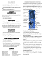
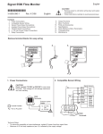
1
9. Rotate the lens turret (item #10) to select the right lens for ideal viewing.
10. The greater the magnification the darker the room should be.
HORIZONTAL PROJECTION
1. Holding the neck of the microprojector with your left hand, place your
right hand around the back of the dust proof revolving disk (item #14 available on X-1000-1 only) and pull the projecting mechanism up into the horizontal position
2. When using liquids and projecting horizontally, the instrument head must
be placed in a vertical position. Bring the specimen into focus while in the
vertical position, then move the mirror (item# 15) into the light path and
adjust so the image appears on the screen. Select the lens desired and refocus.
MODEL TECH A-11
OPERATING INSTRUCTIONS
5. Polarizing
Lens/Analyzer
6. Light Diffusing Lens
8. Stage
15. (5x) Widefield
Auxiliary Lens
7. Stage Clips
9. Focusing Knob
11. 16mm Lens
12. 10mm Lens
13. 6.5mm Lens
10. Revolving Lens
Turret
LIGHT POLARIZATION
1. Rotate the polarizing lens/analyzer (item #6 - white) until the lens is
beneath the light beam.
2. Rotate the dust proof revolving disk (item #14) until the RED “P” on the
edge of the disk is directly below the RED line.
3. Place a slide containing polarizing material on the stage.
4. Bring into focus and change colors by turning the polarizing lens/analyzer. (item #5)
USE AS A MICROSCOPE
(X-1000-1 only)
1. Rotate the auxiliary lens disk (item #14) until the RED “E” on the edge
of the disk is directly below the RED line.
2. Rotate the light diffusing lens (item #5-darker lens) until it is under the
light beam.
3. Place the unit in the horizontal position.
4. View the specimen through the 10X eyepiece tube (item #16).
5. Bring into focus using the 16mm lens; then select the lens desired.
MODEL TRIG
OPERATING INSTRUCTIONS
Instructions covering the use of Ken-A-Vision Microprojector Model X10001 apply except for the following:
1. Under “Vertical Projection” instructions disregard #4. Model Trig has only
one objective lens.
2. Under “Vertical Projection” instructions disregard #7 entirely. Turning
the knob between the two mounting rods adjusts the focus.
3. Under “Vertical Projection” disregard #9 in its entirety.
4. Instructions for the light polarization and use as a microscope are the same as for
Model X1000-1
4. Lamp Housing
1. Lamp Housing Cap
2. Lamp Housing Cap
Screw
3. Horizontal Positioning
Tension Bolt
16. Mirror
VERTICAL PROJECTION
1. Turn the switch to the “ON” position.
2. Place a white sheet of paper between the legs of the base.
3. Rotate lenses (item#5 and #6), polarizing lens (item#14) 5X Wide Field auxiliary
lens (item #15), and the mirror (item #16) so the light beam will not be obstructed.
4. Rotate the revolving lens turret (item#10) containing the three lenses, until the
16mm lens (item#11) is positioned so the light beam penetrates it.
5. Place a specimen slide on the stage (item#8), and center it under the light.
6. Turn the focusing knob (item#9) and lower the stage (item#8) to the lowest position;then reverse the direction until the specimen is brought into focus.
7. To use the 5X Wide Field Auxiliary lens (item#15), move it directly under the
light beam. It can be used with any of these lenses.
8. Rotate the lens turret (item#10) to select the proper lens for ideal viewing.
9. The greater the magnification the darker the room should be.
HORIZONTAL PROJECTION
1. Follow the above instructions; then holding the neck of the microprojector with
your left hand, place your right hand around the back of the focusing knob(item#9),
and pull the projecting mechanism up into the horizontal position.
2. When using liquids and projecting horizontally, the instrument head must be
placed in a vertical position. Bring the specimen into focus while in the vertical position, then move the mirror( item#16) into the light path and adjust so the image
appears on the screen. Select the lens desired and refocus.
LIGHT POLARIZATION
1. Rotate the polarizing lens/analyzer (item #5 - darker lens) until the lens is
beneath the light beam.
2. Rotate the Revolving Lens Turret (item #10) until the RED “P” on the edge of
the disk is directly below the RED line.
3. Place a slide containing polarizing material on the stage (item #8).
4. Bring into focus and change colors by turning the polarizing lens (item #14)
USE AS A MICROSCOPE
(Requires optional 10x eyepiece tube)
1. Rotate the light diffusing lens (item #6) until it is under the light beam.
2. Place the unit in the horizontal position.
3. View the specimen through the 10x eyepiece tube. (optional accessory for this
model)
4. Bring into focus using the focusing knob (item #9)
MODEL TYRO
OPERATING INSTRUCTIONS
Instructions covering the use of the Ken-A-Vision Microprojector Model Tech A-11
apply except for the following:
1. Under”Vertical Projection” discard #4.
2. Under”Vertical Projection” discard #8.
LIGHT POLARIZATION
1.
Rotate the polarizing lens/analyzer (item #5-darker lens and #14) until the lens
es are beneath the light beam.
2. Place a slide containing polarizing material on the stage item (item#8).(Option to
prepare a slide, crumple a small amount of cellophane from a cigarette wrapper, stick
it to a strip of scotch tape approximately 2 inches long; then place it on a slide).
3. Bring into focus and change colors by turning the polarizing lens/analyzer.
1. Lamp Housing Cap
4. Lamp Housing
2. Lamp Housing Cap
Screw
6. Polarizing Lens
Analyzer
3. Horizontal
Positioning Tension Bolt
8. Stage
5. Light Diffusing Lens
7. Stage Clip or Optional
Mechanical Stage
9. Focusing Knob
16. 10x Eyepiece Tube
Model X1000-1
11. 16mm Lens
12. 10mm Lens
13 6.5 mm Lens
10. Revolving Lens
Turret
14. Dust Proof Revolving
Disk
15. Mirror
USE AS A MICROSCOPE
VERTICAL PROJECTION
(requires optional 10x eyepiece tube)
1. Turn the switch to the “ON” position.
2. Place a white sheet of paper between the legs of the base.
3. Rotate lenses (item #5 and #6) and mirror (item #15), so the light
beam will not be obstructed.
4. Rotate revolving lens turrent (item #10) containing the three lenses,
(item #11) is positioned over until the 16mm lens so the light beam
penetrates it.
5. Rotate the Dust Proof Revolving disk (item #14) until the RED “C”
on the side of the disk is directly under the RED line on your upper
disk.
6. Place a specimen slide between the prongs of the mechanical stage
(item #7) or under the stage clips, and center it under the light.
7. Using the focusing knob (item #9), at either side, lower the stage
(item #8) to the lowest position and then reverse the direction until
the specimen is brought into focus.
8. To use the 5x Wide Field auxiliary lens, rotate the revolving dust
proof revolving disk (item #14) until the RED “A” is under the RED
line on the upper disk.
1.
2.
3.
4.
Rotate the light diffusing lens (item#6-white) until it is under the light beam.
Place the unit in the horizontal position.
View the specimen through the 10X eyepiece tube. (Purchase as an accessory.)
Bring into focus using the focusing knob (item#9).
1.
When a lamp burns out, the switch MUST be placed in the “off”
position and the unit UNPLUGGED.
DO NOT replace until lamp has cooled.
Remove the lamp housing cap screws (item#2), lift off the lamp housing cap
(item #1), and replace the defective lamp. Use KAVGE EKL 150W lamp.Use as
soft cloth when replacing the lamp - Do Not touch with your bare hands
KEEP COVERED WHEN NOT IN USE -DUST IS ITS ENEMY
LAMP REPLACEMENT- ALL MICROPROJECTORS
2.
3.
MICROPROJECTOR OPERATING INSTRUCTIONS
The microprojector will project either horizontally or vertically. When
used with a large group or entire class, project from the horizontal
position. For small groups or an individual, projectect vertically. Use
whenever possible, as everyone sees the same image, making it ideal
for study, discussions, and lectures.
ACCESSORIES
(available from the factory)
KAVOL065 6.5mm Lens (43x)
KAVOL016 16mm Lens (10x)
KAVEP001 10x Eyepiece Tube
KAVGEEKL Lamp (Quartz Iodine 150 watt
KAVSCOACT - Laboratory Activity Book
KAVOL010 10mm Lens (20x)
KAVOL030 30mm Lens (4x)
T5045 Mechanical Stage
KAVEXPM Classroom Experimental Manual
T5090 - Vinyl Dust Cover (large)
TO MAKE YOUR OWN MICROSCOPIC SLIDES
You may easily preserve choice specimens for many years by making
your own microscope slides. The only materials required are blank
microscope slides, cover glasses, unflavored gelatin from any grocery
store, and clear cement.
1. In preparing an ordinary specimen first thoroughly clean the slide
a cover glass to be used.
2. Prepare a small quantity of gelatin according to the directions.
Use as little gelatin on the slide as possible, just enough to cover the
speciment without leaving an air bubble when the cover glass is laid
on top.
3. Set the slide aside so that it may “gel” undistrubed.
4. When the gelatin has solidified carefully trim the edges of the
cover glass, removing any gelatin that may have escaped from
beneath the cover glass.
5. Finally, run a thin coat of clear cement around the edges of the
cover glass, which insures an air tight seal.
Care should be taken to make the slide as thin as possible without
crushing the specimen. Sometimes, however, you may wish to mount
a specimen which is rather thick. In this case you should place pillars
under the edges of the cover glass which raises it to the desired thickness. Many times you will find that tiny pieces of a broken cover
glass provide adequate thickness.
WARRANTY
Ken-A-Vision Microprojectors are covered by a lifetime warranty
against defective material or workmanship. If defective, forward to
us, prepaid, and it will be repaired or replaced free of charge for the
life of the instrument. The warranty does not cover normal wear,
breakage, or abuse.
Tel. 816-353-4787 * Fax 816-358-5072
email: [email protected] * www.ken-a-vision.com
INS-MP.V2
MICROPROJECTOR
INSTRUCTION MANUAL
INTRODUCTION
Thank you for the purchase of your Ken-A-Vision Microprojector. It
is important you read the information contained in this manual to
acquaint yourself with the operation, uses, and benefits of your KenA-Vision Microprojector.
With Microprojectors from Ken-A-Vision, any slide that is used on a
microscope can be shown to your entire classroom at the same time.
This ins trument is effectively used from elementary to college level
courses. Ideal in teaching visually impaired and physcially challenged
individuals or groups.
FEATURES
*A
powerful 150 watt quartz iodine lamp with double condensing
system (light intensifying system) provides a crisp, clear projected
image from edge to edge.
* The cooling system fan not only helps preserve living specimens,
but also extends the life of the lamp.
* With the objective lens on the reverse side of the slide, you never
have to worry about the lens touching your medium
* The depth of field of the objective lens enables viewing objects
through a petrie dish.
* Projection can be either vertically onto the table or horizontally
onto a screen or wall.
STANDARD FEATURES
Patented Cooling System
* 150 Watt Quartz Iodine Lamp
* Double Condensing System
* Amalloy Aluminum
* Heat Filtered (Protects Specimens) * UL Registered
* Dust Cover
* 70-80 cm in height
*
USING A CALIBRATED MECHANICAL STAGE
If your Microprojector is equipped with the calibrated mechanical
stage this information will be valuable to you. Besides being an
excellent means of moving specimens across and vertical with the
field of the microprojector, the calibrated scale can measure the
length and width of objects accurately for you. With this as a guide
you may also determine with reasonable accuracy the thickness of
objects using the previous measurements as guides in its relative proportions.
Let us assume that you wish to measure the dimensions of a salt crystal. Follow these steps:
1. Focus your Microprojector sharply on the desired salt crystal.
2. Draw a line at the left side of the crystal on the paper between the
microprojector feet.
3. Read the longitudinal micrometer (the one parallel to the slide).
Read it first to the nearest whole number opposite the 0 mark.
4. Read the tenths up this scale until the lines match up. Write this
down after the whole number.
5. Turn the knob on the mechanical stage until the right side of the
crystal is at the line you drew on the paper.
6. Reread the micrometer as above, and write the number down. The
difference between these two numbers is the width of the crystal in
millimeters and tenths of millimeters (NOTE: one inch equals about
25mm).
7. Follow the same procedure in finding the width of the crystal, this
time drawing the line at the top of the crystal and using the vertical
micrometer (the one at right angles to the slide).
8. By careful focusing through the crystal determine its thickness relative to its other dimensions.