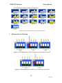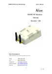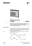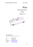
1
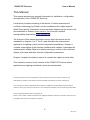
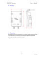
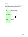
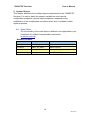
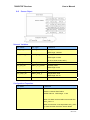
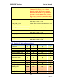
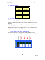
7600RF RF Receiver
User’s Manual
7600RF RF Receiver
Manual
Revision 2.1E
Nico Technology Ltd.
24F,No.37,SanMin Rd, 2.Sec, PanChiao City, Taipei County, Taiwan
Phone
+886-2-2954-5338
Fax
+886-2-2954-5308
Product Info
[email protected]
Technical Support
[email protected]
Web site
http://www.nico-tech.com
1
Rev.2.1E
7600RF RF Receiver
User’s Manual
This Manual
This manual provides any required information for installation, configuration
and operation of the 7600RF RF Receiver.
It exclusively treats the handling of this device. It neither describes the
LonWorks technology by Echelon nor the LonMark profile implemented in
detail. More specific information concerning these subjects can be found in the
documentation of Echelon (www.echelon.com) and the LonMark
Interoperability Association (www.lonmark.org).
The first part of this manual provides a survey about the device and its
installation in chapters 1 to 3. The 2nd part describes the implemented
application for lighting control and its configuration possibilities. Chapter 4
contains a description of the firmware interface while chapter 5 describes the
implemented LonMark Objects in detail providing an outlook of the individual
objects, their tasks and their relevant configuration parameters.
Chapter 6 explains the basics required to connect the objects to each other.
This manual is relevant for all variants of the 7600RF RF Receiver where
applications for lighting and switch control are implemented.
This documentation is subject to modification at any time without prior advice. Nico does not take over any
responsibility for mistakes or inaccuracies in this documentation and eventually occurring consequences.
In any case Nico as well as its representatives and staff are not reliable for eventual defaults, damages caused
indirectly or during use, occurring due to the use or non-usability of the software or the accompanying documentation.
Nico is a registered trademark of Nico Technology Ltd.
Echelon, LON, LonMark, LonWorks and Neuron are registered trademarks of Echelon Corporation. Other name may
be registered trade marks of the respective companies.
2
Rev.2.1E
7600RF RF Receiver
User’s Manual
Contents
Contents .........................................................................................................................3
2
Product Information ...............................................................................................4
3
2.1
Functional Elements...................................................................................4
Installation..............................................................................................................4
4
3.1
Warnings ....................................................................................................5
3.2
Mounting....................................................................................................6
3.3
Connections................................................................................................6
3.4
Software Installation ..................................................................................7
Device Description.................................................................................................8
5
4.1
Hardware Survey .......................................................................................8
4.2
Operation and Display Elements ...............................................................8
4.3
Connection Pin Assignment.......................................................................8
4.4
EMC.........................................................................................................10
4.5
Technical Specifications ..........................................................................10
4.6
Dimensions ..............................................................................................11
Application Software for ECOBINO...................................................................12
6
5.2
Interoperable Interface .............................................................................13
System Objects.....................................................................................................14
6.1
Node Object .............................................................................................14
6.2
Sensor Object ...........................................................................................15
6.3
Default CP Value of Sensor Object..........................................................17
6.4
Battery life measure .................................................................................18
6.5
DIP Switch Setting...................................................................................18
6.5.1
DIP Switch for ON 7xxxRF Sensor devices........................................18
6.5.2
Wireless network Channel ID Setting..................................................19
7
Wireless Sensor ID Setting ..................................................................................19
8
Wireless Frequency scope and PN code ..............................................................20
PN code is for separate channel which is use same wireless frequency channel. .......20
3
Rev.2.1E
7600RF RF Receiver
User’s Manual
2 Product Information
2.1 Functional Elements
Figure 1.1 7600RF RF Receiver
No
Description
1
Wireless antenna
2
Service pin button
3
Service LED indicator
4
DIP switch for wireless channel ID setting
5
LonWorks network connector
6
Power supply. 12~24VDC
2.2 Variants and Identifications
2.3 Scope of Delivery
3 Installation
This chapter first describes the installation of the device; the installation of the
configuration software is described in section 2.4.
4
Rev.2.1E
7600RF RF Receiver
3.1
User’s Manual
Warnings
Attention
The device must be installed in compliance with the relevant DIN/VDE
regulations or the relevant national standards. The connection to the
supply voltage must be performed in accordance with VDE 0100 and VDE
0160 or the relevant national standards. Installation should perform by
qualified and technical experienced personnel only.
CAUTION
At the connections of the LonWorks network 1 – 4 (Fig. 1.1, terminals 5)
and the power supply (terminals 6) 12~24VDC main voltage with load
guard band is accessible. The installation of the unit therefore has to be
effected in a switch cabinet or behind a respective cover.
5
Rev.2.1E
7600RF RF Receiver
3.2
User’s Manual
Mounting
3.3 Connections
The 7600RF has to be connected to a 12 ~24VDC power supply and to the
LonWorks network. According to the respective application peripheral
equipment has to be connected to outputs.
6
Rev.2.1E
7600RF RF Receiver
User’s Manual
Attention
Before connecting peripheral equipment the power supply device has to be
switched off.
The connection is effected by means of the included screw less terminals.
Clamping range of the screw terminals:
- Power supply connections (5.08mm grid, terminals 6): 0.2 – 2.5mm
The pin assignment of the connections is described in chapter 3.1, also
containing wiring details.
Voltage
The 12~24 Volt DC connections are through connected in order to achieve
easy installation.
LonWorks Network
The connection to the LonWorks network is made by means of power line
channels.
Attention
The 7600RF RF Receiver power supply recommend use 24VDC power supply.
3.4 Software Installation
The configuration software of the 7600RF RF Receiver has to be installed
by starting the program Setup.exe on the data carrier provided. It suns
under Windows 9x/2000 and NT.
Download url: http://www.nico-tech.com/download
7
Rev.2.1E
7600RF RF Receiver
User’s Manual
4 Device Description
The 7600RF RF Receiver for LonWorks network in automation. Its peripheral
scope has been specially designed for the use as valve controller for device
spreading control of applications such as valve control or lighting control.
4.1 Hardware Survey
The 7600RF RF Receiver disposes of one LonWorks circuit for each.
4.2 Operation and Display Elements
The 7600RF RF Receiver is fitted with a service button accessible via a
small gap on the front panel (see Figure. 1.1, 8). Activation of the buttons
generates a service-pin message transmitted via the LonWorks network.
The processor status as well as the service-pin status are displayed by the
service LED (figure. 1.1,A), which is on while the service button is
activated.
4.3 Connection Pin Assignment
The following tables show the connector pin assignment of the individual
connectors. Connections the 1 marking cf. Figure. 1.1 On previously page.
In each clamp block pin 1 is situated on the left. For further wiring
information see figure 3.1.
LonWorks Network Connection
The double-core bus line can be connection either to Net . No polarity has
to be considered by connecting the LonWorks network.
8
Rev.2.1E
7600RF RF Receiver
User’s Manual
Figure 3.1 Connector pin assignment LonWorks network
9
Rev.2.1E
7600RF RF Receiver
User’s Manual
4.4 EMC
The 7600RF RF Receiver is a CE certified device according to the
regulation 89/336/EEC for electron magnetic compatibility, modified by
92/31/EEC”. Concerning the emission it fulfills classification B (living area)
according to EN 55022A/B, EN 55011 A/B and EN 50081-1/2 and,
concerning the interference sensibility, classification A (industrial area)
according to EN 50082-2.
4.5
Technical Specifications
CPU
Echelon Neuron 3150,10MHz
Memory
64Kbytes Flash memory, 512Bytes EEPROM,2Kbytes
SRAM,8Kbyte external SRAM
LonWorks Transceiver
FT-X1
Power supply
12~24VDC(24VDC is recommend)
Power consumption
1.5w
Connection
M2.5 screw (Pitch:3.5mm)
Temperature
Operation
Storage
0 ~ +50
-20 ~ +70
Admitted relative humidity
10 ~ 90%, non condensing
Dimensions
60 x 94 x 30 mm,
Mounting
Wall mounting
Display & Operation
Service-pin and Reset LED indicator and button
Max. connections
8 wireless sensor devices
Max trans len
10 Meters
Table 3.1 Technical Specification
10
Rev.2.1E
7600RF RF Receiver
4.6
User’s Manual
Dimensions
Figure 3.5 Device dimensions without plug-screw clamps
11
Rev.2.1E
7600RF RF Receiver
User’s Manual
5 Application Software for ECOBINO
On the 7600RF RF Receiver an application for energy saving control is
implemented, making output functionality as well as switch control functions
available.
Therefore the relevant LonMark profiles stated in Table 4.1 are implemented.
The use of network variables (NV) compiles with the LonMark standard, no
customized network variables are used. SCPT’s are used for parameterization
by applying the read/write-memory method.
Title
Present
Version
Identification
LonMark Application Layer Interoperability Guidelines
V3.1
078-0120-01D
The SNVT Master List and Programmer’s Guide
V 8.0
The SCPT Master List
V 8.0
Sensor Object
Table 4.1 Referring document about LonMark profiles
5.1 System Scope
The 7600RF RF Receiver is equipped between Wireless and LonWorks
channels.
Each Wireless network allows then connection eight wireless sensors.
Sensor Object according to LonMark Standard can be assigned to these
output and configured.
Furthermore the 7600RF RF Receiver can act as constant sensor
controller. The sensor received value from wireless sensor generated by
the internal via an output network variable.
The 7600RF RF Receiver is equipped with one LonWorks communication
circuit to connect LonWorks network.
12
Rev.2.1E
7600RF RF Receiver
User’s Manual
5.2 Interoperable Interface
The LonMark profile 1040,1050,1010 are realized in the 7600RF RF
Receiver. As some customized NVs are used, the network interface
remains standardized, clear and especially it is interoperable. That means,
the 7600RF RF Receiver can be used in connection with network
components by other manufactures. The following table contains a survey
of the network variables defining the 7600RF RF Receiver network
interface and their assignment.
NV Name
Type
Allocated Object
nvo_lux_val
SNVT_lux
Sensor Object
nvo_RH_val
SNVT_lev_percent
Sensor Object
nvo_temp_val
SNVT_temp_p
Sensor Object
Table 4.4 Allocation of NVs and LonMark objects
Under the order code 7600RF a data carrier containing the interface
describing files ECOBINO_WG_P2.XIF and the applications
ECOBINO_WG_P2.APB is provided free of charge at simultaneous
purchase of ECOBINO system. The XIF-file is necessary for integration
with LonMaker for Windows or any other LonWorks network management
tool.
13
Rev.2.1E
7600RF RF Receiver
User’s Manual
6 System Objects
This chapter describes the LonMark objects implemented in the 7600RF RF
Receiver. For each it states the network variable les used, special
configuration properties, general object properties, response during
modification of the configuration and after a reset, and, if available, further
object properties.
6.1
Node Object
The functionality of the node object is defined in the Application Layer
Guidelines of LonMark Interoperability Association
(www.lonmark.org).
Network Variables
NV Name
NV Type
Comment
nviRequest
SNVT_obj_request
Status request
nvoStatus
SNVT_obj_status
Status response
nvoAlarm
SNVT_alarm
Alarm generating
nvoFileDirectory
SNVT_address
Address of file for parameterization
14
Rev.2.1E
7600RF RF Receiver
6.2
User’s Manual
Sensor Object
Network Variables
NV Name
NV Type
Comment
nvo_ave_lux
SNVT_lux
Average value of Lux
Valid range:1~65535
nvo_battery_life
SNVT_lev_percent
Battery life information
Valid ragne:0~100%
(0,10,25,40,55,70,85,100%)
nvo_lux_val
SNVT_lux
Lux value
nvo_RH_val
SNVT_lev_percent
Humidity value
Valid range:0~100
nvo_sensor_alarm
UNVT_sensor_alarm
Sensor Alarm
nvo_temp_val
SNVT_temp_p
Temperature value
Valid range:-50~70
Configuration Properties
CP Name
Comment
error_count
Define how many “No data” error occurs then
send the “Sensor Dead” alarm
Default value:6 Valid range: 1~100
When “No data” received within 30 second then
error_count +1.
When current error count equal then error_count
cp value and then send the “Sensor Dead”
15
Rev.2.1E
7600RF RF Receiver
User’s Manual
alarm.
When any signal is received, reset the
error_count
invalid_count
Define how many “Invalid data” error occurs then
send the “Invalid data” alarm
Default value: 6
Valid range: 1~100
When “Invalid” or “No data” errors received
within 30 secs, then invald_count+1. When
“valid data” is received, reset invalid count.
When current invalid count equals to invalid
count cp value and then send the “Invalid
data” alarm of the sensor.
buffer_size
Define totally of buffer_size. (max: 100)
Default value:100
Valid scope: 1~100
average_calculate_time
For average lux values calculate.(Minute)
default value: 10.( 30 samples)
Every 20 seconds collect a sample from
nvolux_value
Valid scope: 10~255
If samples of buffer not enough then sum all the
value of current sample to division number of
sample.
Ex. Current number of samples: 6
(Value_1 + Value_2 + Value_3 + Value_4 +
Value_5 + Value_6) / 6 = nvo_ave_lux
modification.mod0
Ref. Lux Modification(must change to 1)
Valid range: -1638.4 ~ 1638.3
modification.mod1
Ref. Lux Modification(must change to 1)
Valid range: IEEE 754
modification.mod2
Ref. Lux Modification
Valid range: IEEE 754
modification.dis
Lux modification’s distinction
Valid range: 0 ~ 65535
power_up_value
Default output value for power up sensor
gateway. Before receive first time value of
16
Rev.2.1E
7600RF RF Receiver
User’s Manual
sensor. Valid range: -32768 ~ 32767
[Attention] Do not use copy or dump
function within LM4W when configure
functional block. That can get automatic
generate a correct default value, invalid
high value, invalid low value, alarm high
value and alarm low value.
dead_state_value
Output value of sensor dead alarm occurs.
Valid range: -32768 ~ 32767
invalid_state_value
Output value of sensor invalid data alarm occurs.
Valid range: -32768 ~ 32767
valid_high_limit
Define valid value of scope. (Max)
Valid range: -32768 ~ 32767
value_low_limit
Define valid value of scope. (Min)
Valid range: -32768 ~ 32767
alarm_high_limit
Define alarm value of scope (Max)
Valid range: -32768 ~ 32767
alarm_low_limit
Define alarm value of scope (Min)
Valid range: -32768 ~ 32767
6.3
Default CP Value of Sensor Object
CP Name
Lux
Room Temp
Room Humidity
Freezer
error_count
6
6
6
6
invalid_count
6
6
6
6
buffer_size
100
100
100
100
average_calculate_time
10
10
10
10
modification.mod0
0
0
0
0
modification.mod1
1
1
1
1
modification.mod2
0
0
0
0
modification.dis
0
0
0
0
power_up_value
1
20
50
0
dead_state_value
0
0
0
0
invalid_state_value
0
0
0
0
valid_high_limit
30000
100
99
100
value_low_limit
0
0
0
-40
alarm_high_limit
30000
100
95
25
alarm_low_limit
1
0
0
-25
17
Rev.2.1E
7600RF RF Receiver
6.4
User’s Manual
Battery life measure
Battery Life
Detect voltage
0%
<3
10%
3 ~ 3.25
25%
3.25 ~ 3.5
40%
3.5 ~ 3.75
55%
3.7 5~ 4
70%
4 ~ 4.25
85%
4.25 ~ 4.5
100%
>4.5
6.5 DIP Switch Setting
DIP Switch overview
there are two kinds of DIP Switch for 7600RF Receiver and 7xxxRF serial
Sensors. On 7600RF Receiver have 5 DIP switch for configure setting Wireless
network ID.
On 7xxxRF serial Sensors have 5 DIP switch for configure setting Wireless
network ID (NET ID) and Sensor devices (Sensor ID)
In order to wireless devices can working correct, you have to configure correct
NET ID on Sensor devices and 7600RF devices.
6.5.1 DIP Switch for ON 7xxxRF Sensor devices
The DIP Switch is setting by binary and each 7600RF RF Receiver have to
configure as unique “Network ID”. The valid channel id was between 0 and 15.
Figure 6.1 Identify DIP Switch for 7600RF RF Receiver Wireless network ID
18
Rev.2.1E
7600RF RF Receiver
User’s Manual
6.5.2 Wireless network Channel ID Setting
Figure 6.2 DIP Switch for Wireless network ID on 7600RF RF Receiver
7
Wireless Sensor ID Setting
Figure 7.1 DIP Switch for 7002RF Temperature & Humidify Sensor ID
Figure 7.2 DIP Switch for 7001RF Freezer Temperature Sensor ID
19
Rev.2.1E
7600RF RF Receiver
User’s Manual
Figure 7.3 DIP Switch for 7200RF Lux Sensor ID
8 Wireless Frequency scope and PN code
Channel
ID
Primary
Channel
Second
Channel
PN Code
0
2400 MHz
2440 MHz
0x83,0xF7,0xA8,0x2D,0x7A,0x44,0x64,0xD3
1
2404 MHz
2444 MHz
0x40,0xBA,0x97,0xD5,0x86,0x4F,0xCC,0xD1
2
2409 MHz
2449 MHz
0x3F,0x2C,0x4E,0xAA,0x71,0x48,0x7A,0xC9
3
2414 MHz
2454 MHz
0x17,0xFF,0x9E,0x21,0x36,0x90,0xC7,0x82
4
2419 MHz
2459 MHz
0xA6,0x46,0xB5,0x9A,0x3A,0x30,0xB6,0xAD
5
2424 MHz
2464 MHz
0xBC,0x5D,0x9A,0x5B,0xEE,0x7F,0x42,0xEB
6
2429 MHz
2469 MHz
0x24,0xF5,0xDD,0xF8,0x7A,0x77,0x74,0xE7
7
2434 MHz
2474 MHz
0x3D,0x70,0x7C,0x94,0xDC,0x84,0xAD,0x95
8
2400 MHz
2440 MHz
0x40,0xBA,0x97,0xD5,0x86,0x4F,0xCC,0xD1
9
2404 MHz
2444 MHz
0x3F,0x2C,0x4E,0xAA,0x71,0x48,0x7A,0xC9
10
2409 MHz
2449 MHz
0x17,0xFF,0x9E,0x21,0x36,0x90,0xC7,0x82
11
2414 MHz
2454 MHz
0xA6,0x46,0xB5,0x9A,0x3A,0x30,0xB6,0xAD
12
2419 MHz
2459 MHz
0xBC,0x5D,0x9A,0x5B,0xEE,0x7F,0x42,0xEB
13
2424 MHz
2464 MHz
0x24,0xF5,0xDD,0xF8,0x7A,0x77,0x74,0xE7
14
2429 MHz
2469 MHz
0x3D,0x70,0x7C,0x94,0xDC,0x84,0xAD,0x95
15
2434 MHz
2474 MHz
0x1E,0x6A,0xF0,0x37,0x52,0x7B,0x11,0xD4
PN code is for separate channel which is use same wireless frequency
channel.
Channel 0~7 and 8~15 were use same radio frequency, but there have
different PN code for separate channel identify even there are use same
frequency for wireless transmission. Only correct frequency setting and
PN code then wireless sensor could be communication with receiver.
20
Rev.2.1E