1
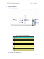
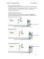
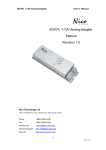
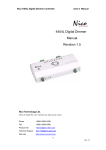
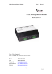
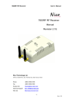
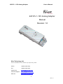
4201PL 1-10V Analog Adapter
User’s Manual
4201PL 1-10V Analog Adapter
Manual
Revision 1.0
Nico Technology Ltd.
24F,No.37,SanMin Rd, 2.Sec, PanChiao City, Taipei County, Taiwan
Phone
+886-2-2954-5338
Fax
+886-2-2954-5308
Product Info
[email protected]
Technical Support
[email protected]
Web site
http://www.nico-tech.com
1
Rev.1.0
4201PL 1-10V Analog Adapter
User’s Manual
2 Product Information
2.1 Functional Elements
Figure 1.1 4201PL 1-10V Analog Adapter
No
Description
1
Output channel for 1-10VDC signal output
2
Output channel for relay output
3
90~260VAC input power
4
Reset LED indicator
5
Reset button
6
Service pin indicator
7
Band In Use indicator
8
9
A
Service Pin button
2.2 Variants and Identifications
4
Rev.1.0
4201PL 1-10V Analog Adapter
User’s Manual
4 Device Description
The 4201PL 1-10V Analog Adapter is a electronic ballast PWM output adapter
for LonWorks network in automation. Its peripheral scope has been specially
designed for the use as fluorescent light controller for device spreading control
of applications such as lighting control.
For the use in lighting the the 4201PL 1-10V Analog Adapter realizes one
independent output channel with one relay output to control conventional
switch.
The LonMark object available per channel flexible use of the the 4201PL 1-10V
Analog Adapter;Furthermore there are several timer functions for the operation
by switch function. The configuration of the lighting control application is
effected via a plug-In.
Of course, the 4201PL 1-10V Analog Adapter is also freeing programmable in
Neuron C. As a flash module is used the application can be load via the
LonWorks network, for the detail please direct contact us.
4.1 Hardware Survey
The the 4201PL 1-10V Analog Adapter disposes of one output circuit for
each. The output circuit can be controlled individually relay output
8A@90~260VAC.
4.2 Operation and Display Elements
The 4201PL 1-10V Analog Adapter is fitted with a service button
accessible via a small gap on the front panel (see Figure. 1.1, A).
Activation of the buttons generates a service-pin message transmitted via
the LonWorks network. The processor status as well as the service-pin
status are displayed by the service LED (figure. 1.1.6), which is on while
the service button is activated. By use the network management function
Wink the service LED flashes.
Furthermore the 4201PL 1-10V Analog Adapter is fitted with a reset LED
(figure. 1.1, 6), displaying the availability of device occur reset. The LED is
connection to an I/O pin of the Neuron chip processor.
8
Rev.1.0
4201PL 1-10V Analog Adapter
User’s Manual
4.3 Connection Pin Assignment
The following tables show the connector pin assignment of the individual
connectors. Connections the 1 marking cf. Figure. 1.1 On previously page.
In each clamp block pin 1 is situated on the left. For further wiring
information see chapter 3.4.
LonWorks Network Connection
The LonWorks Power Line can be direct connection to Power Line.
Without other equipment, but has to be considered by connecting on the
same phase of power line channel
Figure 3.1 Connector pin assignment LonWorks network
Relay output circuit
Figure 3.2 Connector pin assignment output circuit.
1-10V signal output circuit
9
Rev.1.0
4201PL 1-10V Analog Adapter
User’s Manual
4.4 EMC
The 4201PL 1-10V Analog Adapter is a CE certified device according to
the regulation 89/336/EEC for electron magnetic compatibility, modified by
92/31/EEC”. Concerning the emission it fulfills classification B (living area)
according to EN 55022A/B, EN 55011 A/B and EN 50081-1/2 and,
concerning the interference sensibility, classification A (industrial area)
according to EN 50082-2.
4.5
Technical Specifications
CPU
Echelon Neuron 3120,10MHz
Memory
4Kbytes flash EPROM,4Kbytes RAM
LonWorks Transceiver
PL-3120
Power supply
90~260VAC
Power consumption
Connection
Screw less 2.5mm
Temperature
Operation
Storage
0 ~ +50
-20 ~ +70
Admitted relative humidity
10 ~ 90%, non condensing
Dimensions
159 x 27 x 47 mm,
Mounting
Wall mounting
Display & Operation
Service-pin and Reset LED indicator and button
I/O Channels
1 for Relay output channel (max. 8Ampl)
1 for 1-10V output channel
Table 3.1 Technical Specification
4.6
Dimensions
Figure 3.5 Device dimensions without plug-screw clamps
11
Rev.1.0