Transcript
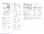
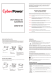
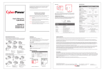
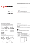
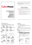
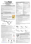
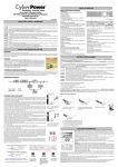
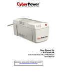
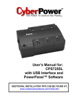
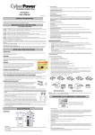
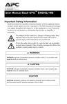
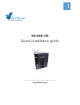
1
R
2
3
4
5
6
User’s Manual for
CyberShield
CS36D12V Front
1. Battery Compartment Cover
2. Control Buttons
(Alarm Silence / Battery
Emergency Use)
3. LED Indicators
(Auxiliary Power Source /
Replace Battery / Battery
Power / System Status)
4. Battery Compartment
5. 9 Pin Connector Compartment
Cover
6. Battery Release Latch
7. Interconnection & Power Cable
Channel
8. Keyhole Screw Slot
9. Pass Through Hole for
Interconnection & Power Cable
7
8
CS36A12V2
9
Bundled kit
(CA50A48V2 + CS36D12V)
CS36D12V Battery Replacement
Operation Guide
OVERVIEW (CS36D12V)
CS36D12V Back
CA50A48V2 Installation Guide
.
AC Power. The unit is now ready to be placed into
Start-Up: Plug the CA50A48V2 power supply into
service. The CS36D12V has four LED indicators and two control buttons. The table below
lists the functions of each.
Fig.2
LED Indicators
Indicator
Color
Condition
c
Alarm Silence Button
Blue
Press and hold the button for 1second to silence the audible alarm.
Battery Emergency
Use Button
Auxiliary Power Source
Blue
Press and hold the button to activate emergency battery capacity.
Green
Replace Battery
Battery Power
Red
Green
System Status
Green
Indicates that an external power source with adequate voltage
(12Vdc) is connected to the CS36D12V.
Battery replacement required.Alarm will beep once every 15 minutes.
Indicates the battery is supplying the power. At 45% battery capacity,
this LED will flash and then alarm will beep 4 times per minute.
Indicates normal mode of operation.
Condition
Status LED
Alarm
Interface
Description
System LED On
Pin 2,3,4,5 in open Condition normal; AC power load, charges battery.
collector state.
Battery is connected and in good condition.
ON Battery
Battery LED On
Pin 2 in Low state 48V input failure or loose connection between
power supply and battery board; battery is supplying
the power.
Replace Battery Replace Battery 1/2 sec beep
Pin 3 in Low state Every 45 days, the unit will automatically initiate a
LED On
battery test. The test lasts 16 hours. If the battery
every 15 min
needs to be replaced, an alarm signal will be sent to
the Central Office.
Battery Missing
None, only ONT Pin 4 in Low state Approximately 6 seconds after battery removal, the
system initiates battery detection routine. Upon
sees alarm
failure, an alarm signal will be sent.
Low Battery
Battery LED Flash 1/2 sec beep
Pin 5 in Low state When battery capacity is < 45% (approximately
12Vdc), unit signals low battery.
every 15 sec
Battery Type
IMPORTANT SAFETY WARNINGS
The battery is a standard sealed lead acid battery rated at 12Vdc / 7.2Ah. If required, the battery may be
replaced with an approved 12Vdc / 7Ah battery.
(SAVE THESE INSTRUCTIONS)
Connection point for customer-supplied DC input voltage (12Vdc). At 45% remaining capacity, the
CS36D12V switches from internal battery to external source. The auxiliary power source supplies power
to the load (ONT) in the event of 48V input voltage failure and a battery capacity of <45%.
Step 1:
a. Open the power connector
.
compartment cover
Step 2:
a. Install output power cable to the 2
position IDC connector
.
(red wire
to positive, black wire to negative).
b. Thread the power cable along the
back of the power connector cover.
Wrap the power cable around the
strain relief lip. Insert the cable
through one of the cable channels
to exit the compartment.
c. Insert the power cable into the
cable channel on the back of
the unit.
Step 3:
a. Place screw in keyhole screw slot
and tighten half way.
b. Slide unit so that the screw rests
against the narrow end of the slot.
c. Place second screw into the screw
hole and tighten securely.
d. Tighten keyhole slot. screw securely.
e. Close the power connector
compartment cover
Maintenance Mode
Maintenance mode determines remaining useful battery life. During the 16 hour test, the battery is
discharge to determine its state. The unit measures the rate of change in the battery charge. If the rate of
discharge is excessive, the battery replacement indicator is activated.
90 ~ 135Vac
57 - 63Hz
Yes
47.5 ~ 52Vdc
47.5 ~ 52Vdc
13.8Vdc
10.5 ~ 13.8Vdc
36W
48W
<200 MV RMS
Insulation Displacement Connector (IDC)
Sealed, Maintenance Free Lead-Acid Battery
7.2Ah / 12V
12Vdc / 1.3mm COAX Power Jack
AC Power
The CS36D12V enters the maintenance mode approximately once every 45 days.
In the event that the CS36D12V is in the maintenance mode and an AC failure occurs, maintenance
mode will cease and the CS36D12V will supply the power to the load.
The CS36A12V2 is another excellent UPS in CyberPower’s CyberSheild line of reliable Optical
Network Terminal (ONT) power solutions. The CS36A12V2 provides increased flexibility and cost
effectiveness by separating the power supply unit (CA50A48V2) from the battery back up unit
(CS36D12V). The power supply plugs into a 110/120Vac outlet. It converts the power to 48Vdc, which
is then fed through a power cord to the battery back up unit. The battery back up unit feeds 12Vdc to
the ONT.
Management
Communication Interface
Physical
Maximum Dimensions (L*W*D)
Weight (lb)
Environment
Operating Temperature
Operating Humidity
Max Operating Elevation
Max Storage Elevation
Storage Temperature
CS36D12V
Auxiliary Power Source /
Replace Battery /
Battery / System
AC Fail / Replace Battery
Replace Battery /
Low Battery
Signal Retun / On Battery /
Replace Battery / Missing
Battery / Low Battery
3.94 x 2.65 x 1.56 in
0.77
6.89 x 6.75 x 3.47 in
1.51
32oF - 104oF (0 - 40oC)
0 - 95% noncondensing within enclosure
10,000ft (3,000m)
50,000ft (15,000m)
o
5oF - 113oF (-15oC - +45 C)
FCC NOTICE:
CS36D12V Installation Guide
This equipment has been tested and found to comply with the limit for a Class B digital device, pursuant to part 15 of the FCC Rules. These limits are designed to provide protection against
harmful interference in a residential installation. This equipment generates, uses and can radiate radio frequency energy and, if not installed and used in accordance with these instructions, may cause harmful
interference to radio communications. However, there is no guarantee that interference will not occur in a particular installation. If this equipment does cause harmful interference to radio or television reception,
which can be determined by turning the equipment off and on, the user is encouraged to try to correct the interference by one or more of the following measures: (1)Reorient or relocate the receiving antenna.
(2) Increase the separation between the equipment and receiver. (3) Connect the equipment into an outlet on a circuit different from that to which the receiver is connected. (4) Consult the dealer or an
experienced radio/TV technician for help.
A
SYSTEM BLOCK DIAGRAM
CAUTION: Any changes or modifications not expressly approved by Cyber Power could void the authority granted by the FCC to operate this equipment.
a
b
CA50A48V2
CS36D12V
Power Supply
Battery Back Up
48Vdc
Input
Voltage Range
Frequency Range
Surge Protection
Output
Output Voltage (Normal)
Output Voltage (Battery Mode)
Output Power Continuous
Ripple
Connector Type
Battery
Battery Type
Numbers of Battery
Auxiliary Input Power
Warning Diagnostics
Indicators
CA50A48V2
Auxiliary Power Connection (AUX)
NOTE : Please use appropriate size screws to mount the CS50A48V2 on the wall.
110/120Vac
Specification
Alarm
CAUTION! To prevent the risk of fire or electric shock, install in a temperature and humidity
controlled indoor area free of conductive contaminants. (Please see specifications for
acceptable temperature and humidity range.)
INTRODUCTION
Step 2:
a. Replace battery cable on the new battery.
b. Place the new battery into battery compartment.
c. Close the battery cover.
Batteries are considered HAZARDOUS WASTE and must be disposed of properly.
Most retailers that sell batteries collect used batteries for recycling.
This manual contains important instructions regarding the installation and operation of this device.
Read this manual thoroughly before attempting to unpack, install or operate this device
CAUTION! To reduce the risk of electric shock, do not remove the cover except to service the
battery. No user serviceable parts are inside except the battery.
Step 1:
a. Press battery cover catch (A) and slide the cover to the left
to remove.
b. Remove the battery connector.(See Fig.2)
c. Remove the battery strain relief lip to remove battery.
Model
Status LED, Alarm & Communication Signals
Normal
A
Step 1:
a. Press the battery cover release latch (A) and
slide the cover to remove.
b. Remove the 9 pin connector compartment
cover by pulling outward.
ONT
Step 2:
a. Insert the power and interconnection cables
into the back cable channel. Feed the
cable end into the 9 pin connector
compartment.
b. Securely mount the unit on the wall with 2
mounting screws.
12Vdc
NOTE :
For more information, please contact:
Cyber Power Systems (USA), Inc. 5555 12th Avenue East, Suite 110, Shakopee, MN55379
Cyber Power Systems (EUROPE), Inc.. Rietwaard 2, 5236 WB, ‘s-Hertogenbosch, Netherlands
Phone: (877) 297-6937 Fax: (952)403-0009
E-mail: [email protected]
www.cyberpowersystems.com
www.cyberpower-eu.com
Please use appropriate size screws to mount the CS50A48V2 on the wall.
ENCLOSURE INSTALLATION
Carefully follow these instructions during the installation of this device:
1.) Carry out the installation in a safe area that is free of excessive dust and has adequate airflow.
2.) Screws must be appropriate for total weight of the UPS unit and the mounting surface material
.
3.) Do not operate the UPS where the temperature and humidity are outside the specified limits.
(Refer to specifications in this manual.)
Fig.1
OVERVIEW (CA50A48V2)
1
a
2
3
6
7
Step 3:
a. Remove protective shipping terminal covers from
the battery if necessary
b. Connect the battery cable leads to the appropriate
terminals; red to postive, black to negative.
c. Insert the battery into the battery compartment.
d. Install the 9 position IDC connector to the unit. (see Fig.1)
c
b
Step 4:
a. Install both power and interconnection cables to
the 9 position IDC connector
(See case for the pin assignments)
b. Close the 9 pin connector compartment cover.
c. Close the battery cover.
7. Cable Channel
8. Input Power Cord (8 ft.)
4
5
8
CA50A48V2 Front
1.Power Connector
Compartment Cover
2. Strain Relief Lip
3. 2 Pin IDC Connector
4. Power LED Indicator
5. Screw Hole
6. Keyhole Screw Slot
c
Vin +
Vin Vout +
Vout Signal Return
On Battery
Replace Battery
Missing Battery
Low Battery
The UPS battery charges when it is connected to utility power. The battery charges
fully during the first 24 hours of normal operation. Do not expect full battery run
capability during this initial charge period.
CA50A48V2 Back
K01-3612000-00