1
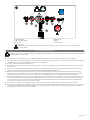
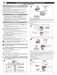
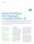
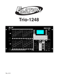
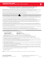
INSTRUCTION GUIDE COMMAND POST BLACKLITE ADJUSTABLE-HEIGHT SEATPOST THIS BRIEF INSTRUCTION GUIDE CONTAINS IMPORTANT INFORMATION. PLEASE READ CAREFULLY AND STORE IN A SAFE PLACE. Congratulations! The Command Post BlackLite is among the finest products available in mountain biking. This guide contains instructions, warnings, and torque specifications to be used in conjunction with the owner’s manuals and other instruction guides supplied with your bicycle. Failure to follow the warnings in this instruction guide may result in a catastrophic failure of the Command Post, which can result in serious personal injury or death. This phrase may not be repeated in connection with each and every warning. Visit your favorite Specialized Authorized Dealer if you have any doubt regarding your mechanical proficiency and ability to install this product. Specialized recommends that the Command Post be installed by a qualified bicycle mechanic. WARNINGS Air pressure determines rate of return; more PSI, faster rise. Never exceed 40 psi (2.76 bar) in the Command Post air chamber. Before riding, operate the Command Post and ensure the return rate is not excessive, or else injury might occur while riding. This applies equally to boys and girls. An incorrect sizing interface can result in slippage and/or failure of the Command Post, causing serious personal injury or death. Ensure your seat tube is made to accept a 30.9mm or 31.6mm seatpost, and nothing else. For carbon frames, use of friction paste is optional. Seat collar torque requirements can vary depending on the specific frame and seat collar used. Exceeding the maximum torque limit can result in damage to the Command Post and/or frame, which can result in a loss of control of the bicycle and serious personal injury or death. The Command Post is marked with a minimum insertion line. This is the minimum amount of insertion required for the Command Post to remain structurally safe. Also, some frames require additional insertion to ensure that the frame remains structurally sound. The bottom end of the Command Post should extend past the underside of the top tube. Activating the Command Post lever while riding may result in loss of control of the bicycle, resulting in serious personal injury or death. Before slaying singletrack, practice using the Command Post in the parking lot, on grass, or around the house (your call on this one). Master before using. The air chamber must be fully discharged before performing any service. Discharge the air chamber with the Command Post in the fully extended position or you might end up in a world of hurt. Recommended torques in this instruction guide are specific for the Command Post. Consult your bicycle owner’s manual for recommended torque specifications for other parts. When mating parts, use the lower torque recommendation. Get and use a torque wrench! Verify the cable housing length and check the full range of the Command Post travel. Make sure the cable housing is kink-free, and that it does not interfere with any bicycle components or clothing as it goes up and down through its travel, nor interfere with handlebar movement. INSTALLING THE SEATPOST Before beginning installation, ensure the following items are in the box: Command Post BlackLite Cable and cable housing Inline barrel adjuster Hinged lever (Aftermarket only) Three (3) ferrules Noodle (90-degree pipe) Cable end Integrated grip lever (Original Equipment only) 1. Aluminum frames: Grease the seat tube I.D. (Inside Diameter) and Command Post O.D. (Outside Diameter). Carbon frames: Do not use grease. Use of friction compound paste on the seat tube I.D. and Command Post O.D. is optional. 2. Command Post air pressure is factory set to 25 psi. Air pressure determines the return rate. Do not exceed 40 psi (2.76 bar). 3. The Command Post ships in the compressed (Descender; see Fig. 7) position. Depress the plunger lever (Fig. 1, item H) and slowly allow the Command Post to extend to the fully extended (Power) position. 4. Insert the Command Post into the seat tube. It should slide into the seat tube in a straight and smooth manner, and there should not be any play. If you experience any fit and/or torque issues, have a Specialized Authorized Dealer verify fit tolerances. 5. Grease the inside surfaces of the wedges (Fig. 1, items B) and saddle head cups. Place the wedges into the saddle head cups, with the angled sides of the wedges facing the saddle head. 6. Slide the saddle rails onto the wedges. Try sliding the saddle on from the top side of the wedges; the rails should “snap” on to the wedges. Adjust the saddle according to rider preference (tilt, and fore and aft positions). 7. Place the clamps (Fig. 1, items A & C) onto the wedges and rail clamps. It doesn’t matter which side you put the clamps on. Apply blue threadlocker (Loctite 242) to the bolt (Fig. 1, item D) threads. Insert the bolt through the bolt-side rail clamp (Fig. 1, item C), screw it into the nut rail clamp (Fig. 1, item A), then torque the bolt to 120 in-lbf (13.5 N*m). 8. With the Command Post fully extended, determine saddle height as you would using a standard seatpost, then tighten the seat collar. To minimize dirt contamination from the rear wheel, position the seat collar so that the slot faces forward. Loosen the bolt and rotate the saddle out of the way. The following collars have been tested for use with the Command Post, and are recommended: Specialized fixed and Q/R collars Salsa Flip-Lock Q/Rs NOTE: Do not overtighten. Use only hand pressure on the Q/R lever. Use only enough tension to keep the post from slipping. SPECIALIZED BICYCLE COMPONENTS 15130 Concord Circle, Morgan Hill, CA 95037 (408) 779-6229 IG0293 Rev.C, March 2011 Please note all instructions are subject to change for improvement without notice. Please visit www.specialized.com for periodic tech updates. Feedback: [email protected] Page 1 of 6 3 1 G D A B B C F E A.Nut Rail Clamp C.Bolt-side Rail Clamp E. Inner Tube G.Plunger Lever B.Wedge (2) D.Bolt F. Saddle Head Mechanism can bind slightly when rotating to achieve desired angle. If this occurs, apply pressure to (or lightly tap) the top of the saddle. INSTALLING THE REMOTE LEVER The OE remote lever can be integrated with the Specialized locking grip by replacing the locking clamp on the grip, or mounted separately with any grip by using the supplied shim. 1. If you are using a non-Specialized grip, use the supplied shim by inserting it inside the lever collar before sliding it onto the handlebars. 2. Loosen the 3mm hex and slide the grip/lever (or lever only) onto the handlebars. Slide on the remote, shifter, and brake levers in the order preferred. The AM lever (Fig. 5, item C) is hinged and mounts directly to the handlebars. 3. Torque the 3mm hex to 15 in-lbf (1.7 N*m) (Fig. 5). 4. Operate the remote lever to ensure it doesn’t interfere with other controls on the handlebar. Loosen the hex screw to relocate the lever if necessary, then re-tighten. 5. Lubricate the cable and insert it through the slot on the remote lever, then through the non-grommeted end of the noodle (Fig. 2, item C). Pull the cable through until the cable head rests in the slot. Do not insert it into the cable housing just yet. 6. Determine cable housing length by running it from the noodle to the saddle head (Fig. 3, item F) assembly. Route it through and/or around any frame features—be sure measure twice and cut once! Make sure the Command Post is in the extended position, and that there is enough slack to compensate for turning the handlebars to their extreme positions. It is imperative that the cable housing is kink-free along its full length. 7. Install the inline barrel adjuster by cutting the cable housing at the point where you want the barrel adjuster located. The most common position is in front of the handlebars: Cut the cable about 6 inches (150mm) from the end of the noodle to achieve this location. Use the included ferrules on the ends of the cable housing on both sides of the inline barrel adjuster. To provide adjustment range after installation, turn the barrel adjuster two full turns counter-clockwise (see direction arrow on Fig. 2, item G. 8. Run the cable through the cable housing/ferrules/inline barrel adjuster. (A ferrule is not needed where the cable housing exits the noodle.) 9. Route the cable housing/cable to the saddle head. Place a ferrule on the cable housing. (On some bicycle models, you may be able to route the cable housing through internal routing ports built into the frame or through outboard clips along the top tube. Consult your bicycle’s owner’s manual for more information on cable routing features, if available.) Page 2 of 6 2 1 A B D C E F G A.Cable end C.Noodle (90-degree pipe) E. Ferrules (3) G.Inline barrel adjuster H B.Aftermarket lever D.Cable F. Cable housing H.Counter-clockwise direction shown 2 3 & 17mm A B Some Specialized QR seat collars are equipped with a cable guide slot on the inside of the lever. 10.With the cable pulled taut in the cable housing, place the bottom of the barrel 17mm above the top of the ferrule. Tighten the 2.5mm hex to approximately 10 in-lbf (1.1 N*m), using a 4mm hex on the other side of the barrel for leverage. 11. Place the barrel into the slot on the plunger lever, pull down (Fig. 3, item A) on the cable housing, then slide the ferrule into the slot (Fig. 3, item B) in the bottom of the saddle head. There should be a little play to prevent placing tension on the plunger lever; doing so can cause your seatpost to accidentally move positions while riding. Adjust play by using the inline barrel adjuster (Fig. 2, item G). 12. Cut off excess cable with cable cutters, leaving at least 1” past the barrel. Place a cable tip on the cable end. You can bend the cable towards the back of the bike so that it’ll be tucked in nicely underneath the saddle. 13. Rotate the saddle back into position, then tighten the saddle head bolt to 120 in-lbf (13.5 N*m). 14. While weighing the saddle with your elbow/forearm, press the remote lever and allow the saddle to drop and rise; make sure the Command Post locks in all three positions (Fig. 7). Watching your head, press the remote lever to check the return rate. Adjust air pressure, if needed. Refer to the Troubleshooting table on the next page if you encounter any issues. Page 3 of 6 SETUP AND USE The remote lever is used to activate the Command Post: »» The Command Post has three different positions: Descender (fully compressed); Cruiser (center position); and Power (fully extended). See Fig. 7. »» To move the saddle down, press the remote lever, and guide the saddle down to the next lower position. If the lever is difficult to move, unweight the saddle ever so slightly while pressing the lever. »» To move the saddle up, press the remote lever and, while maintaining contact with the saddle, guide the saddle to the next higher position. Specialized has a special tune for riders in colder climates (50°F/10°C and below, tundra, etc.), which involves using a lower viscosity lubricant. Visit a Specialized Authorized Dealer for more information. Store and transport the Command Post in the Descender position to prevent nicks and/or scratches to the inner tube (Fig. 1, item E), which can lead to air loss. Before performing any service, release air pressure in the Command Post while in the fully extended (Power) position. Make sure the Command Post is in the fully extended position when adding air. MAINTENANCE Routine maintenance of the Command Post is crucial to peak performance. Vigilantly maintain the following service regimen to keep your Command Post tip-top: Before every ride: Clean the exposed portion of the inner tube with a rag. Check the inner tube for scratches, nicks, etc. (Visit a Specialized Authorized Dealer if there is any damage to the inner tube.) Make sure the lever action is smooth and that the cable is kink-free. Lubricate the inner tube (Fig. 1, item E) if the Command Post has been idle for several weeks. Inspect the Command Post for any damage that might require warranty service (read the Limited Warranty below). Use it or lose it! Every 3 months: Use a standard shock pump to check and increase/decrease air pressure to between the 20 — 40 psi (1.38 — 2.76 bar) range. Lubricate the inner tube and cycle the Command Post up and down a few times. Lubricate the actuating cable at both ends. Adjust the inline adjuster barrel as needed so that there is a small amount of slack in the cable (slightly tap the lever to feel the slack; there should be a small amount at the top of lever throw). If ridden in muddy/rainy conditions, lubricate the cable and cable housing with a Teflon-based lubricant (e.g., Tri-Flow®). Every 6 months: Have your local Specialized Authorized Dealer inspect the Command Post. This is important: If any issues are discovered, you are still covered by the Limited Warranty (see below). After 1 year or 150 hours: Have your local Specialized Authorized Dealer service the Command Post. If you ride in extreme conditions (dirt, mud, sand dunes, tundra, Morgan Hill, etc.), you might need to service your Command Post sooner. Replace the cable and cable housing, then check functionality. If the Command Post becomes inoperable after a cable/cable housing change, see a Specialized Authorized Dealer. TROUBLESHOOTING Issue/Symptom Cause Solution Action between positions is sticky Grease has migrated from sliding surfaces Apply lubricant to sliding tube (inner tube) surface and around the seal head then cycle post to re-lube seals Lack of grease Disassemble, clean, then lube internal parts* Pressure bleeds through seal over time Increase air pressure to desired setting / Check inner tube for nicks and/or scratches* Pressure bleeds through seal over time Increase air pressure to desired setting / Check inner tube for nicks and/or scratches* Grease has migrated from sliding surfaces Lube sliding tube (inner tube) Post internal parts have been contaminated Disassemble, clean, then lube internal parts* Pressure is set too low Increase air pressure to workable range Cable and housing friction Lubricate or replace cable/cable housing Plunger is too low Reset plunger height* Too little cable tension Increase tension by turning the inline barrel adjuster counter-clockwise (see Fig. 2, item H) Cable and housing friction Lubricate or replace cable/cable housing Plunger is too high Reset plunger height* Too much cable tension Reduce tension by turning the inline barrel adjuster clockwise (see Fig. 2, item H) Air leakage due to main seal damage Replace seal head assembly* Inner tube surface has nicks and/or scratches Replace inner tube assembly* Grease has migrated from sliding surfaces Lubricate the inner tube Slow return to the Power position Post does not move when lever is activated Post moves without activating lever Slow/No return action 2-3 days after setting air pressure *To preserve your warranty, this service/procedure must be performed by a Specialized Authorized Dealer. LIMITED WARRANTY Subject to the following limitations, terms, and conditions, Specialized warrants to the original purchaser of the Command Post BlackLite that such when new is free of defects in materials and workmanship. This warranty may be exercised for a period of up to one year from the date of purchase. This limited warranty does not apply to normal wear and tear, nor to claimed defects, malfunctions or failures that result from abuse, neglect, improper assembly, improper maintenance, alteration, collision, crash, or misuse. In order to exercise rights under this warranty, customer must return the affected product to Specialized with proof of purchase. This instruction guide contains usage and maintenance information. Visit www. specialized.com for additional terms and conditions of this warranty. Page 4 of 6 4 A B C A.Carbon frames: Do not grease the seat tube I.D. nor Command Post O.D. (Carbon friction paste is optional.) B.Aluminum frames: Grease the seat tube I.D. and Command Post O.D. 5 C.Grease the seat collar tightening bolt, and torque to the proper specification. A quick-release lever can also be used. 5 A B C A.OE ONLY: The remote lever is integrated with the Specialized locking grip. The shim is not used. B.Use the shim when the remote lever is not being used with a Specialized locking grip. In this case, slide the remote lever—with shim—directly onto the handlebars. C.Hinged aftermarket remote lever Page 5 of 6 6 To ensure that there is enough slack in the system, the cable housing/cable/ferrule must enter the saddle head in a straightforward manner, with the Command Post in the fully extended position. 7 POWER CRUISER DESCENDER a: 35mm b: 35mm c: 25mm MODEL a: 125mm b: 100mm c: 75mm a: 90mm b: 65mm c: 50mm Depending on the model, your Command Post has 125 (a), 100 (b), or 75 (c) millimeters of travel. Travel is measured from the top of the seal head wiper to the bottom of the saddle head assembly. Page 6 of 6