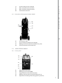
1
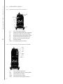
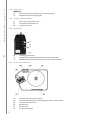
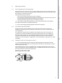
Kempoweld
3200, 3200W
Operating manual • English
Käyttöohje • Suomi
EN
FI
Bruksanvisning • Svenska
SV
Bruksanvisning • Norsk
NO
Brugsanvisning • Dansk
DA
Gebrauchsanweisung • Deutsch
DE
Gebruiksaanwijzing • Nederlands
NL
Manuel d’utilisation • Français
FR
Instrukcja obsługi • Polski
PL
Инструкции по эксплуатации • По-русски
RU
Operating manual
English
Kempoweld 3200, 3200W / © Kemppi Oy / 1117
Kempoweld 3200, 3200W / © Kemppi Oy / 1117
Contents
1.PREFACE. ........................................ . . . . . . . . . . . . . . . . . . . . . . . . . . . . . . . . . . . . . . . . . . . . . . . . . . . . . . . . . . . . . . . . . . . . . . . . . . . . . . . . . . . . . . . . 3
1.1General. ............................................... . . . . . . . . . . . . . . . . . . . . . . . . . . . . . . . . . . . . . . . . . . . . . . . . . . . . . . . . . . . . . . . . . . . . . . . . . . . . . . . . . . . . . . . . 3
1.2 Product introduction. .................... . . . . . . . . . . . . . . . . . . . . . . . . . . . . . . . . . . . . . . . . . . . . . . . . . . . . . . . . . . . . . . . . . . . . . . . . . . . . . . . . . . . . . . . . 3
1.3 Kempoweld panels. ........................ . . . . . . . . . . . . . . . . . . . . . . . . . . . . . . . . . . . . . . . . . . . . . . . . . . . . . . . . . . . . . . . . . . . . . . . . . . . . . . . . . . . . . . . . 4
1.3.1 Operation control and connectors. . . . . . . . . . . . . . . . . . . . . . . . . . . . . . . . . . . . . . . . . . . . . . . . . . . . . . . . . . . . . . . . . . . . . . . . . . . . . . . . . . 4
1.3.2 Parts of cooling unit Kempoweld 3200W. . . . . . . . . . . . . . . . . . . . . . . . . . . . . . . . . . . . . . . . . . . . . . . . . . . . . . . . . . . . . . . . . . . . . . . 4
1.3.3 Rear plate of Kempoweld 3200, 3200W. . . . . . . . . . . . . . . . . . . . . . . . . . . . . . . . . . . . . . . . . . . . . . . . . . . . . . . . . . . . . . . . . . . . . . . . . . 5
1.4 Wire feeder panels. ......................... . . . . . . . . . . . . . . . . . . . . . . . . . . . . . . . . . . . . . . . . . . . . . . . . . . . . . . . . . . . . . . . . . . . . . . . . . . . . . . . . . . . . . . . . 5
1.4.1 Front panel. ............................... . . . . . . . . . . . . . . . . . . . . . . . . . . . . . . . . . . . . . . . . . . . . . . . . . . . . . . . . . . . . . . . . . . . . . . . . . . . . . . . . . . . . . . . . 5
1.4.2Accessories. ............................... . . . . . . . . . . . . . . . . . . . . . . . . . . . . . . . . . . . . . . . . . . . . . . . . . . . . . . . . . . . . . . . . . . . . . . . . . . . . . . . . . . . . . . . . 6
1.4.3 Cooling unit connections......... . . . . . . . . . . . . . . . . . . . . . . . . . . . . . . . . . . . . . . . . . . . . . . . . . . . . . . . . . . . . . . . . . . . . . . . . . . . . . . . . . . . . . . . . 6
1.4.4 Rear panel. ................................ . . . . . . . . . . . . . . . . . . . . . . . . . . . . . . . . . . . . . . . . . . . . . . . . . . . . . . . . . . . . . . . . . . . . . . . . . . . . . . . . . . . . . . . . 6
1.4.5 Inside wire feeder unit.. ............ . . . . . . . . . . . . . . . . . . . . . . . . . . . . . . . . . . . . . . . . . . . . . . . . . . . . . . . . . . . . . . . . . . . . . . . . . . . . . . . . . . . . . . . . 6
2.Installation.......................... . . . . . . . . . . . . . . . . . . . . . . . . . . . . . . . . . . . . . . . . . . . . . . . . . . . . . . . . . . . . . . . . . . . . . . . . . . . . . . . . . . . . . . . . 7
2.1
2.2
2.3
2.4
2.5
Positioning of the machine. ........ . . . . . . . . . . . . . . . . . . . . . . . . . . . . . . . . . . . . . . . . . . . . . . . . . . . . . . . . . . . . . . . . . . . . . . . . . . . . . . . . . . . . . . . . 7
Distribution network...................... . . . . . . . . . . . . . . . . . . . . . . . . . . . . . . . . . . . . . . . . . . . . . . . . . . . . . . . . . . . . . . . . . . . . . . . . . . . . . . . . . . . . . . . . 7
Connection to the mains supply. . . . . . . . . . . . . . . . . . . . . . . . . . . . . . . . . . . . . . . . . . . . . . . . . . . . . . . . . . . . . . . . . . . . . . . . . . . . . . . . . . . . . . . 7
Welding and return current cables. . . . . . . . . . . . . . . . . . . . . . . . . . . . . . . . . . . . . . . . . . . . . . . . . . . . . . . . . . . . . . . . . . . . . . . . . . . . . . . . . . . 8
Operation and use of controls.... . . . . . . . . . . . . . . . . . . . . . . . . . . . . . . . . . . . . . . . . . . . . . . . . . . . . . . . . . . . . . . . . . . . . . . . . . . . . . . . . . . . . . . . . 9
2.5.1 Main switch (S1)........................ . . . . . . . . . . . . . . . . . . . . . . . . . . . . . . . . . . . . . . . . . . . . . . . . . . . . . . . . . . . . . . . . . . . . . . . . . . . . . . . . . . . . . . . . 9
2.5.2 Adjustment of welding voltage, . . . . . . . . . . . . . . . . . . . . . . . . . . . . . . . . . . . . . . . . . . . . . . . . . . . . . . . . . . . . . . . . . . . . . . . . . . . . . . . . . . . . . 9
2.5.3 Pilot lamps................................. . . . . . . . . . . . . . . . . . . . . . . . . . . . . . . . . . . . . . . . . . . . . . . . . . . . . . . . . . . . . . . . . . . . . . . . . . . . . . . . . . . . . . . . . 9
2.5.4 Control fuse (F1)........................ . . . . . . . . . . . . . . . . . . . . . . . . . . . . . . . . . . . . . . . . . . . . . . . . . . . . . . . . . . . . . . . . . . . . . . . . . . . . . . . . . . . . . . . . 9
2.5.5 Adjustment for arc roughness . . . . . . . . . . . . . . . . . . . . . . . . . . . . . . . . . . . . . . . . . . . . . . . . . . . . . . . . . . . . . . . . . . . . . . . . . . . . . . . . . . . . . . . . 9
2.5.6 Operation of cooling fan. ......... . . . . . . . . . . . . . . . . . . . . . . . . . . . . . . . . . . . . . . . . . . . . . . . . . . . . . . . . . . . . . . . . . . . . . . . . . . . . . . . . . . . . . . . . 9
2.5.7 Accessory drawer...................... . . . . . . . . . . . . . . . . . . . . . . . . . . . . . . . . . . . . . . . . . . . . . . . . . . . . . . . . . . . . . . . . . . . . . . . . . . . . . . . . . . . . . . 10
2.5.8 Adjustment for wire feed. ........ . . . . . . . . . . . . . . . . . . . . . . . . . . . . . . . . . . . . . . . . . . . . . . . . . . . . . . . . . . . . . . . . . . . . . . . . . . . . . . . . . . . . . . 10
2.6 Volt / ampere metering unit msd-1.. . . . . . . . . . . . . . . . . . . . . . . . . . . . . . . . . . . . . . . . . . . . . . . . . . . . . . . . . . . . . . . . . . . . . . . . . . . . . . . 10
2.7 Cooling unit. ...................................... . . . . . . . . . . . . . . . . . . . . . . . . . . . . . . . . . . . . . . . . . . . . . . . . . . . . . . . . . . . . . . . . . . . . . . . . . . . . . . . . . . . . . . 10
2.7.1 Installation of cooling............... . . . . . . . . . . . . . . . . . . . . . . . . . . . . . . . . . . . . . . . . . . . . . . . . . . . . . . . . . . . . . . . . . . . . . . . . . . . . . . . . . . . . . . 10
2.7.2 Operation switches................... . . . . . . . . . . . . . . . . . . . . . . . . . . . . . . . . . . . . . . . . . . . . . . . . . . . . . . . . . . . . . . . . . . . . . . . . . . . . . . . . . . . . . . 11
EN
3. Operation disturbances. . . . . . . . . . . . . . . . . . . . . . . . . . . . . . . . . . . . . . . . . . . . . . . . . . . . . . . . . . . . . . . . . . . . . . . . . . . . . 12
4.Maintenance......................... . . . . . . . . . . . . . . . . . . . . . . . . . . . . . . . . . . . . . . . . . . . . . . . . . . . . . . . . . . . . . . . . . . . . . . . . . . . . . . . . . . . . . . 13
4.1 Disposal of the machine............... . . . . . . . . . . . . . . . . . . . . . . . . . . . . . . . . . . . . . . . . . . . . . . . . . . . . . . . . . . . . . . . . . . . . . . . . . . . . . . . . . . . . . . 13
5.
6.
2
Ordering numbers. ....... . . . . . . . . . . . . . . . . . . . . . . . . . . . . . . . . . . . . . . . . . . . . . . . . . . . . . . . . . . . . . . . . . . . . . . . . . . . . . . . . . . . . . . 14
technical data................... . . . . . . . . . . . . . . . . . . . . . . . . . . . . . . . . . . . . . . . . . . . . . . . . . . . . . . . . . . . . . . . . . . . . . . . . . . . . . . . . . . . . . . 16
PREFACE
1.1
General
Congratulations on choosing the Kempoweld power source. Used correctly, Kemppi products
can significantly increase the productivity of your welding, and provide years of economical
service.
This operating manual contains important information on the use, maintenance and safety of
your Kemppi product. The technical specifications of the equipment can be found at the end
of the manual.
Please read the manual carefully before using the equipment for the first time. For your
own safety and that of your working environment, pay particular attention to the safety
instructions in the manual.
For more information on Kemppi products, contact Kemppi Oy, consult an authorised Kemppi
dealer, or visit the Kemppi web site at www.kemppi.com.
The specifications presented in this manual are subject to change without prior notice.
Important notes
Items in the manual that require particular attention in order to minimise damage and
personal harm are indicated with the ’NOTE!’ notation. Read these sections carefully and follow
their instructions.
Kempoweld 3200, 3200W / © Kemppi Oy / 1117
1.
Disclaimer
While every effort has been made to ensure that the information contained in this guide
is accurate and complete, no liability can be accepted for any errors or omissions. Kemppi
reserves the right to change the specification of the product described at any time without
prior notice. Do not copy, record, reproduce or transmit the contents of this guide without
prior permission from Kemppi.
1.2
EN
Product introduction
The power sources Kempoweld 3200 and 3200W with wire feeder unit WIRE 400 makes
together 320 A MIG welding equipment, which is suitable for heavy industrial use. To the
product range belong in addition also the power sources Kempoweld 4200, 4200W and
5500W. Kempoweld 3200W has inbuilt water cooling unit.
Power source: Supply voltage of the power source is 3~ 230 V / 400 V. Voltage of power
source is adjusted with turn type switches; together 40 steps. The Volt/Ampere metering unit
MSD-1 (accessory) which is included in the power source displays voltage or welding current.
Wire feeder unit: The wire feeder unit WIRE 400 is a 4-roll driven unit, which is suitable for airor liquid-cooled guns. The unit may be turnable above the power source or it may be locked at
its place. You can use the WIRE 400 wire feeder unit equipped also with interconnection cable
and push-pull gun. KMW timer controls continuous, spot and cycle-arc welding. Accessory
unit KMW sync is needed for connection and use of push-pull guns.
3
Kempoweld 3200, 3200W / © Kemppi Oy / 1117
1.3
Kempoweld panels
1.3.1 Operation control and connectors
05
S1, H1
H2
S2
S3
X2
X1
S1
S2
S3
H2
X1
X2
05
MSD-1
EN
Main switch (pilot lamp H1)
Voltage selecting switch (coarse grading)
Voltage selecting switch (fine grading)
Pilot lamp for overheating (power source)
Return current connector (coarser arc)
Return current connector (softer arc)
Accessory drawer
V/A metering unit (accessory)
1.3.2 Parts of cooling unit Kempoweld 3200W
Sw1
F2
S4
Sw2
Hw4
Hw3
MSD-1
S4
Sw1
Sw2
Hw4
Hw3
4
Main switch of cooling unit
Selecting switch for gun´s cooling mode
Water cooling test switch
Pilot lamp for overheating
Pilot lamp for lacking water pressure
Fuse for cooling unit (2 A delayed)
Water circulation return connector
Water circulation output connector
Filler hole for water tank
Kempoweld 3200, 3200W / © Kemppi Oy / 1117
F2
02
03
04
1.3.3 Rear plate of Kempoweld 3200, 3200W
02
03
F1
X4
01
X3
EN
01
F1
X3
X4
1.4
Inlet of mains cable
Fuse of auxiliary transformer (8 A delayed)
Welding current connector for wire feeder unit (+ pole)
Control connector for wire feeder unit
Wire feeder panels
1.4.1 Front panel
K1
K2
R1
R2
K3
X1
X1
01
02
R1
X1
K1
K2
R2
Adjustment for wire feed
Welding gun connector (EURO)
Trigger function mode (continuous/hold)
Welding mode selection (continuous/spot/cycle arc)
Adjustment for welding mode timing (spot or cycle time)
5
Kempoweld 3200, 3200W / © Kemppi Oy / 1117
1.4.2 Accessories
KMW sync
K3
X1
Wire feed adjustment selection (panel or push-pull gun)
Control connector for push-pull gun
1.4.3 Cooling unit connections
01
02
04
Return water connector for gun
Feed water connector for gun
Inlet of water hoses
1.4.4 Rear panel
X3
X2
03
04
EN
03
X2
X3
Shielding gas connector
Control cable connector (Kempoweld or interconnection cable)
Welding current connection (Kempoweld or interconnection cable)
1.4.5 Inside wire feeder unit
K4
R3
04
05
06
07
6
Wire inch switch (wire feed into gun)
Burn back time adjustment (according to filler material and wire feed)
Locking device for wire reel
Box door latch
Box door lock
Wire feed mechanism
Installation
2.1
Positioning of the machine
Place the machine on a firm, dry and level surface. Where possible, do not allow dust or other
impurities to enter the machines cooling air flow. Preferably site the machine above floor level;
for example on a suitable carriage unit.
Notes for positioning the machine
• The surface inclination should not exceed 15 degrees.
• Ensure the free circulation of the cooling air. There must be at least 20 cm of free space in
front of and behind the machine for cooling air to circulate.
• Protect the machine against heavy rain and direct sunshine.
Note! The machine should not be operated in the rain as the protection class of the machine,
IP23S, allows for outside preserving and storage only.
Note! Never aim metallic grinding spray/sparks towards the equipment.
2.2
Distribution network
All regular electrical devices without special circuits generate harmonic currents into
distribution network. High rates of harmonic current may cause losses and disturbance to
some equipment.
This equipment complies with IEC 61000-3-12 provided that the short-circuit power Ssc
is greater than or equal to 0.9 MVA at the interface point between the user’s supply and
the public supply network. It is the responsibility of the installer or user of the equipment
to ensure, by consultation with the distribution network operator if necessary, that the
equipment is connected only to a supply with a short-circuit power Ssc greater than or equal
to 0.9 MVA.
2.3
Kempoweld 3200, 3200W / © Kemppi Oy / 1117
2.
EN
Connection to the mains supply
Note! Connection and change of the mains cable and the plug must be carried out only by a
competent electrician. Remove for the mounting of the mains cable the left side plate, seen from
the front of the power source.
The Kempoweld power source is equipped with 5 m supply cable without plug. The mains
cable is according to the marking H07RN-F of the norm CENELEC HD22.The mains cable must
be changed if it does not meet local regulations.
Mounting of the mains cable
05
7
Kempoweld 3200, 3200W / © Kemppi Oy / 1117
The cable is entered into the machine through the inlet ring on the rear wall of the machine
and locked with a cable clamp (05).
The phase conductors of the cable are coupled to connectors L1, L2 and L3. The earth
protection coloured green-yellow is coupled to connector marked with earth protection
. If you are using 5-conductor cable, you must cut the zero conductor to the level of
symbol
the cable´s protective shield.
Sizes of mains cables and fuse ratings for the machine at 100% ED duty cycle are
specified in the table below:
Kempoweld 3200, 3200W
Connected voltage
230 V
400 V
Voltage range
Fuses, delayed
Connected cable
380 – 415 V
16 A
4 x 2.5 S mm²
220 – 240 V
20 A
4 x 2.5 S mm²
In cables of S type there is protective grounding conductor coloured green-yellow.
Note! This equipment’s electromagnetic compatibility (EMC) is designed for use in an industrial
environment. Class A equipment is not intended for use in residential location where the electrical
power is provided by the public low-voltage supply system.
Change of mains voltage
Connection 3~ 230 or 3~ 400 V of mains voltage
EN
By delivery from the factory the machine has been connected for mains voltage 3~ 400 V.
In order to change the mains voltage, remove the side plate of the machine. Change the
connections according to the enclosed diagram. You find the corresponding wiring diagram
on the instruction label, which is under terminal block.
2.4
Welding and return current cables
Use only copper cables with cross-sectional area of at least 50 mm². In enclosed table
are shown typical loading capacities of rubber insulated copper cables, when ambient
temperature is 25 °C and conductor temperature is 85 °C.
cable cross-section
duty cycle ED
voltage loss / 10 m
Cu
100 %
60 %
40 %
for 100 A
50 mm²
285 A
370 A
450 A
0.35 V
Fasten the earthing press of the return current cable carefully, preferably direct onto the piece
to be welded. The contact surface area of the press should always be as large and steady as
possible.
Do not overload welding cables over permissible values due to voltage losses and heating.
Clean the contact surface from paint and rust.
8
Operation and use of controls
See the page for Kempoweld PANELS and COOLING UNIT.
2.5.1 Main switch (S1)
In zero position all control and welding current circuits of the equipment are dead (without
voltage). In position I the control circuits of the machine become live (get voltage). The
primary and welding circuits are dead, if the welding mode has not been started with the gun
trigger.
Note! Always switch on and switch off the machine from the main switch. Never use the mains
plug for switching on or switching off the units and equipment!
2.5.2 Adjustment of welding voltage,
Table of adjustments, switch positions:
coarse control
fine control
open circuit voltage
1/4
1 / 10 – 10 / 10
15.5 – 18.2 V
2/4
1 / 10 – 10 / 10
18.6 – 22.5 V
3/4
1 / 10 – 10 / 10
23.1 – 29.3 V
4/4
1 / 10 – 10 / 10
30.4 – 41.6 V
Kempoweld 3200, 3200W / © Kemppi Oy / 1117
2.5
The welding voltage is adjusted with two turn switches. The S2 is the 4-step switch for coarse
control, where voltage value of each step can be fine-adjusted with the 10-step switch S3.
2.5.3 Pilot lamps
Pilot lamps of the machine report about electric function:
EN
The green pilot lamp H1 indicating that the machine is ready for operation is always lit, when
the machine is connected to mains voltage and the main switch is on position I.
The yellow pilot lamp H2 is lit, when thermal protection of the welding circuit has released
due to overheating. The protection releases if the power source is continuously loaded over
rated values or the cooling air circulation has been obstructed.
2.5.4 Control fuse (F1)
On the rear plate of the power source the fuse (F1) 8 A delayed is the short-circuit protection.
Use the fuse size and type according to markings. Damage caused by a wrong type fuse is not
covered by the guarantee. If the fuse is blowing again, send the unit to service.
2.5.5 Adjustment for arc roughness
Arc roughness is adjusted by connecting the return current cable to the applicable one of the
two dix-connectors on the front plate.
The connector marked with shorter symbol gives a rougher arc, which is used for welding
of thin sheets and ferrous metals by 0.6 – 1.0 mm wires and especially with CO² shielding
gas. The connector marked with longer symbol is suitable for thicker wires and especially for
aluminium and stainless materials. The most suitable roughness is, however, most dependent
on the welding case. You will find the best position by testing the different positions.
2.5.6 Operation of cooling fan
The cooling fan on the rear plate of the Kempoweld 3200 equipment is started and stopped
according to use. The cooling fan is controlled by the gun trigger and control circuits. The
cooling fan is started after ca. 15 s after weld start and stopped after ca. 10 min after weld end
or release of the overheat protection.
Note! Do not switch off the unit with the main switch before the cooling fan has automatically
stopped. By open circuit the cooling fan does not get started.
9
Kempoweld 3200, 3200W / © Kemppi Oy / 1117
2.5.7 Accessory drawer
In the accessory drawer in the cover part of the unit are by delivery the plastic guide tubes
needed for welding of aluminium and stainless steels. In the drawer are also the screw and the
insulation bushings needed for locking of rotation of the wire feeder Kempoweld WIRE 400.
2.5.8 Adjustment for wire feed
The wire feed is adjusted from the potentiometer on the control panel of the wire feeder unit
Kempoweld WIRE 400. The adjustment has been described in the operation instructions of the
wire feeder unit.
2.6
Volt / ampere metering unit msd-1
For the mounting of the MSD-1 remove the cover plate on the front panel of the unit.
The connector of flat cable fastened to the cover plate is connected to the corresponding
connector of the MSD-1. From the metering unit you can with lever switch select momentary
display for either voltage or current. By open circuit only voltage value is displayed, because
there is no welding current present.
The voltage value is the voltage between the unit´s welding connectors or terminal voltage.
The value of the open circuit voltage has not very much importance for the welding, so that
the display of the metering unit is adjusted according to the welding situation. The display
of the open circuit voltage differs 2 – 3 V from the true voltage. During welding the terminal
voltage is varying and the arc voltage differs from the terminal voltage due to cable etc. losses.
Accuracy of voltage true value in respect to real value is ±4,0 %, ±0,2 V by welding values
according to the norm.
Accuracy of current true value in respect to real value is ±2,5 %, ±2 A.
The metering unit does not show wire feed values.
The MSD-1 does not need any calibration in the Kempoweld power source.
The switch positions: V = voltage display, A = current display.
EN
2.7
Cooling unit
Kempoweld 3200W power source has inbuilt cooling unit.
2.7.1 Installation of cooling
The cooling unit is connected to the gun by means of water hoses, which are mounted to the
wire feeder unit. The interconnection cable contains also the water hoses, which are mounted
to the gun through the wire feeder unit without any extension parts. See operation instruction
for Kempoweld WIRE feeders.
Before connection check that in the hoses are no dirt, metal powder, rubber waste etc. The
connectors for hoses and cooling unit are marked with red or blue identification rings or
spots. Blue is colour for water supplied from cooling unit to gun and red is colour for water
returning back from gun to cooling unit.
The cooling unit´s tank is filled with 40 % antifreeze according to British Standard BS3151. If
the circumstances do not require frost resistance, you can use a more dilute mixture, or some
other mixture, of which you have good experriences.
Tank volume is ca. 3 litres, volume of gun and interconnection cable is 0.3 – 1.5 litres. Filling of
hoses takes 5 s – 3 min time. Check the return flow to the tank. Before filling check that tank,
cooling water, pouring tank etc. are clean, and that there is no metal powder, waste etc.
10
2.7.2 Operation switches
In zero (O) position of the power source´s main switch also all operations of the cooling unit
are stopped.
Cooling unit´s main switch O / I
The electric supply for the pump motor is switched on by main switch key O / I, where the
pilot lamp indicates the standby state I. In zero (O) position of the main switch the pump
motor cannot get started, but the switches and pilot lamps are operating.
Fuse (F2)
The fuse on the front wall of the cooling unit is short-circuit protection. Use the fuse size and
type according to markings. If the fuse is blowing again, send the unit to service.
Kempoweld 3200, 3200W / © Kemppi Oy / 1117
Note! If the water does not start circulating, see paragraph Operation disturbances: “The water does
not circulate ... etc.
Do not let any waste and dirt into the water circulation! Check filling volume before starting to weld!
Use the cooling liquid according to recommendations, or the one you know as good beforehand.
Watch over liquid material´s quality and possible sediments in hoses of the gun.
Do not swallow cooling liquid. If somebody has swallowed the liquid, take him immediately to
medical care. Avoid contact with skin and eyes, wash the liquid from your skin with clean water.
Selecting switch for gun’s cooling mode (Sw1)
The Kempoweld equipment are suitable to be used with both air- and water-cooled guns.
Select cooling mode and correct use and protection functions with switch on the cooling
unit´s panel.
If your choice is GAS, but you are using water-cooled gun, no protection is operating. The pilot
lamp is illuminated in position I of the cooling unit´s main switch. However, the control does
not start the pump.
The wrong choice will destroy the gun in short time!
If your choice is (water), but you are using air-cooled gun, the pump gets started by
pressing on the trigger, if the cooling unit´s main switch is in position I.
Test switch (Sw5)
By TEST switch on the panel of the cooling unit you can circulate water without starting
welding. It is used for filling the gun and interconnection cable with cooling water before
starting welding. By disturbance situations you can always test the water circulation. Always
check entry of return water into the tank before welding!
Pilot lamps
Pilot lamp for overheating (Hw4)
If the cooling water in the tank is overheating, the thermal protection will stop the power
source. Operation of the cooling unit is continued for ca. 5 – 7 min automatically. The pilot
lamp will switch off after the water in the tank has cooled down, after which the welding will
start from the gun triggering.
Pilot lamp for lacking liquid pressure (Hw3)
If the pump does not step up sufficient supply pressure, e.g. when the water is running out
or by disturbances in the pump, the whole equipment will stop after ca. 5 s and the red pilot
lamp illuminates. Check the equipment like by the installation. See paragraph for OPERATION
DISTURBANCES.
Operating control
The water circulation gets automatically started, when you are pressing on the gun trigger.
The post-circulation of water will continue for ca. 5 – 7 min. after the weld end. The time is
always counted from the latest trigger release.
11
EN
Kempoweld 3200, 3200W / © Kemppi Oy / 1117
3.
Operation disturbances
By the operation or functional disturbances take the measures according to the following list.
If the disturbance cannot be eliminated, check the equipment according to the paragraphs
Installation and Maintenance, and take contact with Authorized Kemppi repair workshop.
The pump does not get started by test switch:
•
•
•
•
check the fuse on the front plate of the cooling unit
check the fuse on the rear plate of the power source
check position for cooling mode selecting switch
check positions for main switches
The water does not circulate by lever switch:
• check the tank filling volume
• disconnect the connector for the return water hose of the gun from the rear wall of the
cooling unit and use thet test switch
If the water is pumped, close the connector and run again by the test switch
A good tip: Blow compressed air into the tank; closing the filling opening by hand is enough.
The water is pumping, but does not return back to the tank or the return flow is
weak:
• filling of interconnection cable can take several minutes
• if you have lifted the gun or interconnection cable for the filling time many meters
higher than the power source, the filling will happen considerably slower. Fill the hoses
on the floor position.
• check the whole flowing line connector by connector
The water is pumping, but during welding the red pilot lamp for the water
pressure is lit and the equipment is stopped:
EN
1.
2.
3.
4.
5.
• check the cooling water volume and return flow to the tank
• in the system are air bubbles or leakages, especially check the connections of the cooling
unit.
• the pressure switch set value (ca. 1 bar) is unsuitable for the gun you are using:
Open the side plate. In the middle at the upper end of the pressure guard connected to
the pump is the adjusting screw for limit value.
Use the pump during the adjustment by the test switch.
After ca. 5 s use twist the screw carefully until the pilot lamp is switched off.
Check the result by welding.
If the adjustment and checkings do not eliminate the disturbance, take contact with the
Authorized Kemppi repair workshop.
During welding the yellow pilot lamp for overheating is lit and the equipment is
stopped:
• release the trigger. When the lamp is switched off, the operation has been reset
automatically
• check if the gun is suitable for power you are using
• check condition of connectors and connections in the welding current circuit
12
Maintenance
The amount of use and the working environment should be taken into consideration
when planning the frequency of maintenance of the machine. Careful use and preventive
maintenance will help to ensure trouble-free operation.
Cables
Check the condition of welding and connection cables daily. Do not use faulty cables! Make
sure that the mains connection cables in use are safe and according to regulations! The
repair and mounting of mains connection cables should be carried out only by an authorized
electrician.
Power source
NOTE! Disconnect the plug of the power source from the mains socket before removing the cover
plate.
Check at least every 6 months (twice a year):
• Electric connections of the unit - clean the oxidized parts and tighten the loosened ones.
NOTE! You must know correct tension torques before starting the repair of the joints.
• Clean the inner parts of the machine from dust and dirt e.g. with soft brush and vacuum
cleaner.
Do not use compressed air, there is a risk that dirt is packed even more tightly into gaps of
components!
Do not use pressure washing device!
Only authorized electrician shall carry out repairs to the machines.
Kempoweld 3200, 3200W / © Kemppi Oy / 1117
4.
Regular maintenance
Kemppi service repair workshops make regular maintenance according to agreement.
The major points in the maintenance procedure are listed as follows:
• Cleaning of the machine
• Checking and maintenance of the welding tools
• Checking of connectors, switches and potentiometers
• Checking of electric connections
• Metering units checking
• Checking of mains cable and plug
• Damaged parts or parts in bad connection are replaced by new ones
• Maintenance testing. Operation and performance values of the equipment are checked,
and adjusted when necessary by means of test equipment.
4.1
Disposal of the machine
Do not dispose of electrical equipment with normal waste!
In observance of European Directive 2002/96/EC on waste electrical and electronic
equipment, and its implementation in accordance with national law, electrical equipment
that has reached the end of its life must be collected separately and taken to an appropriate
environmentally responsible recycling facility.
The owner of the equipment is obliged to deliver a decommissioned unit to a regional
collection centre, per the instructions of local authorities or a Kemppi representative. By
applying this European Directive you will improve the environment and human health.
13
EN
Kempoweld 3200, 3200W / © Kemppi Oy / 1117
5.
Ordering numbers
Units
Kempoweld 3200
230 V / 400 V
621532002
Kempoweld 3200W
230 V / 400 V
621632002
Wire feeder unit
Kempoweld WIRE 400
621740001
Accessories
KMW sync 2
6219150
MSD-1
6185666
P500 transport unit (feeder)
6185265
KV400 swing arm
6185247
KV400 50-1.5-GH
6260351
KV400 50-1.7-WH
6260353
Hub for wire reel
4289880
Branch cable KMP/Kempoweld
3151360
MIG guns
Air-cooled:
EN
KMG 32
3m
6253033
KMG 32
4,5 m
6253034
MMT 32
3m
6253213MMT
MMT 32
4.5 m
6253214MMT
MMT 35
3m
6253513MMT
MMT 35
4,5 m
6253514MMT
WS 35 (Al 1.2)
6m
6253516A12
WS 35 (SS 1.0)
6m
6253516S10
KMP 300
6m
6257306
KMP 300
10 m
6257310
MT 51W
3m
6255046
MT 51W
4.5 m
6255047
MMT 30W
3m
6253043MMT
MMT 30W
4.5 m
6253044MMT
KMP 400W
6m
6257406
KMP 400W
10 m
6257410
WS 30W (Al 1.2-1.6)
6m
6253046A12
WS 30W (SS 1.0)
6m
6253046S10
WS 30W (SS 1.2)
6m
6253046S12
WS 30W (Al 1.2-1.6)
8m
6253048A12
WS 30W (SS 1.0)
8m
6253048S10
WS 30W (SS 1.2)
8m
6253048S12
Liquid-cooled:
14
Kempoweld 3200, 3200W / © Kemppi Oy / 1117
Air-cooled interconnection cables
Mounting cables for short distance:
KW 50-1.3-GH
6260350
Interconnection cables for long distance:
Multimig 50-5-GH
626010401
Multimig 50-10-GH
626010601
Liquid-cooled interconnection cables
Mounting cables for short distance:
KW 50-1.5-WH
6260352
Interconnection cables for long distance:
KW 50-5-WH
626035401
KW 50-10-WH
626035601
Return current cable
5 m - 50 mm²
6184511
EN
15
Kempoweld 3200, 3200W / © Kemppi Oy / 1117
6.
technical data
Kempoweld
Connection voltage
3200
3200W
3 ~ 400 V 380 V -10 % ... 415 V +6 %
380 V -10 % ... 415 V +6 %
3 ~ 230 V 220 V -10 % ... 240 V +6 %
220 V -10 % ... 240 V +6 %
Connection capacity 230 V / 400 V
40 % ED 13,6 kVA
13,6 kVA
60 % ED 10,0 kVA
10,0 kVA
100 % ED 6,6 kVA
6,6 kVA
Main cable / fuses
Connection to wire feeder unit
- Fuse delayed
Loading capacity (nominal values)
Control range 40 steps
Open circuit voltage 40 steps
Open circuit power
Efficiency
Power factor
Temperature class
Operation temperature range
Storage temperature range
Degree of protection
EMC class
Minimun short circuit power Ssc of
supply network *
Cooling unit power
- Fuse delayed
External dimensions
EN
Weight
* See paragraph 2.2
16
220 - 240 V 4 x 2,5 mm² / 20 A delayed
4 x 2,5 mm² / 20 A delayed
380 - 415 V 4 x 2,5 mm² / 16 A delayed
4 x 2,5 mm² / 16 A delayed
30 V / 250 VA
30 V / 250 VA
8A
8A
40 % ED 320 A / 32 V
320 A / 32 V
60 % ED 265 A / 27 V
265 A / 27 V
100 % ED 205 A / 24 V
205 A / 24 V
40 – 320 A / 15 – 32 V
40 – 320 A / 15 – 32 V
15 – 40 V
15 – 40 V
< 50 W
< 50 W
320 A / 32 V 75 %
75 %
320 A / 32 V 0,95
0,95
H (180 °C)
H (180 °C)
-20 ... +60 °C
-20 ... +60 °C
-40 ... +60 °C
-40 ... +60 °C
IP23S
IP23S
A
A
0.9 MVA
0.9 MVA
---
230 V / 250 VA
---
2A
lenght 990 mm
990 mm
width 530 mm
530 mm
height 880 mm
1090 mm
106 kg
118 kg
EN
17
Kempoweld 3200, 3200W / © Kemppi Oy / 1117
KEMPPI OY
Hennalankatu 39
PL 13
FIN-15801 LAHTI
FINLAND
Tel +358 3 899 11
Telefax +358 3 899 428
[email protected]
www.kemppi.com
KEMPPI (UK) Ltd
Martti Kemppi Building
Fraser Road
Priory Business Park
BEDFORD, MK44 3WH
UNITED KINGDOM
Tel +44 (0)845 6444201
Telefax +44 (0)845 6444202
[email protected]
Kotimaan myynti:
Tel +358 3 899 11
Telefax +358 3 734 8398
[email protected]
KEMPPI FRANCE S.A.S.
65 Avenue de la Couronne des Prés
78681 EPONE CEDEX
FRANCE
Tel +33 1 30 90 04 40
Telefax +33 1 30 90 04 45
[email protected]
KEMPPI SVERIGE AB
Box 717
S-194 27 UPPLANDS VÄSBY
SVERIGE
Tel +46 8 590 783 00
Telefax +46 8 590 823 94
[email protected]
KEMPPI NORGE A/S
Postboks 2151, Postterminalen
N-3103 TØNSBERG
NORGE
Tel +47 33 346000
Telefax +47 33 346010
[email protected]
KEMPPI DANMARK A/S
Literbuen 11
DK-2740 SKOVLUNDE
DANMARK
Tel +45 4494 1677
Telefax +45 4494 1536
[email protected]
KEMPPI BENELUX B.V.
Postbus 5603
NL-4801 EA BREDA
NEDERLAND
Tel +31 765717750
Telefax +31 765716345
[email protected]
ООО КЕМППИ
ул. Полковая 1, строение 6
127018 Москва
Tel +7 495 739 4304
Telefax +7 495 739 4305
[email protected]
KEMPPI, TRADING (BEIJING) COMPANY,
LIMITED
Room 420, 3 Zone, Building B,
No.12 Hongda North Street,
Beijing Economic Development Zone,
100176 Beijing
CHINA
Tel +86-10-6787 6064
+86-10-6787 1282
Telefax +86-10-6787 5259
[email protected]
KEMPPI SPÓŁKA Z O.O.
Ul. Borzymowska 32
03-565 WARSZAWA
POLAND
Tel +48 22 7816162
Telefax +48 22 7816505
[email protected]
肯倍贸易(北京)有限公司
中国北京经济技术开发区宏达北路12号
创新大厦B座三区420室 (100176)
KEMPPI AUSTRALIA PTY LTD.
13 Cullen Place
P.O. Box 5256, Greystanes NSW 2145
SMITHFIELD NSW 2164
AUSTRALIA
Tel. +61 2 9605 9500
Telefax +61 2 9605 5999
[email protected]
KEMPPI INDIA PVT LTD
LAKSHMI TOWERS
New No. 2/770,
First Main Road,
KAZURA Gardens,
Neelangarai,
CHENNAI - 600 041
TAMIL NADU
Tel +91-44-4567 1200
Telefax +91-44-4567 1234
[email protected]
电话: +86-10-6787 6064
+86-10-6787 1282
传真: +86-10-6787 5259
[email protected]
1922010
1117
www.kemppi.com
KEMPPI GmbH
Otto-Hahn-Straße 14
D-35510 BUTZBACH
DEUTSCHLAND
Tel +49 6033 88 020
Telefax +49 6033 72 528
[email protected]
OOO KEMPPI
Polkovaya str. 1, Building 6
127018 MOSCOW
RUSSIA
Tel +7 495 739 4304
Telefax +7 495 739 4305
[email protected]