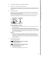
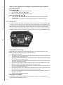
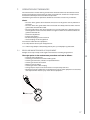
1
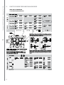
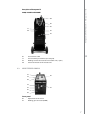
Kempoweld
WIRE 400, 550
Operating manual • English
Käyttöohje • Suomi
EN
FI
Bruksanvisning • Svenska
SV
Bruksanvisning • Norsk
NO
Brugsanvisning • Dansk
DA
Gebrauchsanweisung • Deutsch
DE
Gebruiksaanwijzing • Nederlands
NL
Manuel d’utilisation • Français
FR
Инструкции по эксплуатации • По-русски
RU
Operating manual
English
Kempoweld WIRE 400, 550 / © Kemppi Oy / 1128
Kempoweld WIRE 400, 550 / © Kemppi Oy / 1128
Contents
1.PREFACE. ........................................ . . . . . . . . . . . . . . . . . . . . . . . . . . . . . . . . . . . . . . . . . . . . . . . . . . . . . . . . . . . . . . . . . . . . . . . . . . . . . . . . . . . . . . . . 3
1.1General. ............................................... . . . . . . . . . . . . . . . . . . . . . . . . . . . . . . . . . . . . . . . . . . . . . . . . . . . . . . . . . . . . . . . . . . . . . . . . . . . . . . . . . . . . . . . . 3
1.2 Product introduction. .................... . . . . . . . . . . . . . . . . . . . . . . . . . . . . . . . . . . . . . . . . . . . . . . . . . . . . . . . . . . . . . . . . . . . . . . . . . . . . . . . . . . . . . . . . 3
2.Parts of wire feed mechanism WIRE.. . . . . . . . . . . . . . . . . . . . . . . . . . . . . . . . . . . . . . . . . . . . . . . . 4
3. Kempoweld panels. ....... . . . . . . . . . . . . . . . . . . . . . . . . . . . . . . . . . . . . . . . . . . . . . . . . . . . . . . . . . . . . . . . . . . . . . . . . . . . . . . . . . . . . . . . . 5
3.1
3.2
3.3
3.4
Operation control and connectors. . . . . . . . . . . . . . . . . . . . . . . . . . . . . . . . . . . . . . . . . . . . . . . . . . . . . . . . . . . . . . . . . . . . . . . . . . . . . . . . . . . 5
Parts of cooling unit Kempoweld 4200W and 5500W.. . . . . . . . . . . . . . . . . . . . . . . . . . . . . . . . . . . . . . . . . . . . . . 6
Wire feeder panels. ......................... . . . . . . . . . . . . . . . . . . . . . . . . . . . . . . . . . . . . . . . . . . . . . . . . . . . . . . . . . . . . . . . . . . . . . . . . . . . . . . . . . . . . . . . . 7
Inside wire feeder unit. . ................. . . . . . . . . . . . . . . . . . . . . . . . . . . . . . . . . . . . . . . . . . . . . . . . . . . . . . . . . . . . . . . . . . . . . . . . . . . . . . . . . . . . . . . . . 9
4.ASSEMBLY OF KEMPOWELD EQUIPMENT.. . . . . . . . . . . . . . . . . . . . . . . . . . . . . . . . . . . . . . . . . . . . . . 9
5.INSTALLATION.......................... . . . . . . . . . . . . . . . . . . . . . . . . . . . . . . . . . . . . . . . . . . . . . . . . . . . . . . . . . . . . . . . . . . . . . . . . . . . . . . . . . . . . . . 11
EN
5.1
5.2
5.3
5.4
5.5
5.6
5.7
5.8
5.9
5.10
Accessories corresponding to wire diameter. . . . . . . . . . . . . . . . . . . . . . . . . . . . . . . . . . . . . . . . . . . . . . . . . . . . . . . . . . . . . 11
Mounting of MIG welding gun... . . . . . . . . . . . . . . . . . . . . . . . . . . . . . . . . . . . . . . . . . . . . . . . . . . . . . . . . . . . . . . . . . . . . . . . . . . . . . . . . . . . . . . 11
Mounting and locking of wire reel. . . . . . . . . . . . . . . . . . . . . . . . . . . . . . . . . . . . . . . . . . . . . . . . . . . . . . . . . . . . . . . . . . . . . . . . . . . . . . . . . 12
Accessory drawer............................ . . . . . . . . . . . . . . . . . . . . . . . . . . . . . . . . . . . . . . . . . . . . . . . . . . . . . . . . . . . . . . . . . . . . . . . . . . . . . . . . . . . . . . 12
Automatic wire feed to gun........ . . . . . . . . . . . . . . . . . . . . . . . . . . . . . . . . . . . . . . . . . . . . . . . . . . . . . . . . . . . . . . . . . . . . . . . . . . . . . . . . . . . . . . 12
Adjustment of pressure................. . . . . . . . . . . . . . . . . . . . . . . . . . . . . . . . . . . . . . . . . . . . . . . . . . . . . . . . . . . . . . . . . . . . . . . . . . . . . . . . . . . . . . . 12
Adjustment of tightness of reel brake.. . . . . . . . . . . . . . . . . . . . . . . . . . . . . . . . . . . . . . . . . . . . . . . . . . . . . . . . . . . . . . . . . . . . . . . . . . 13
Return current cable...................... . . . . . . . . . . . . . . . . . . . . . . . . . . . . . . . . . . . . . . . . . . . . . . . . . . . . . . . . . . . . . . . . . . . . . . . . . . . . . . . . . . . . . . 13
Cooling unit . ..................................... . . . . . . . . . . . . . . . . . . . . . . . . . . . . . . . . . . . . . . . . . . . . . . . . . . . . . . . . . . . . . . . . . . . . . . . . . . . . . . . . . . . . . . 13
Shield gas. .......................................... . . . . . . . . . . . . . . . . . . . . . . . . . . . . . . . . . . . . . . . . . . . . . . . . . . . . . . . . . . . . . . . . . . . . . . . . . . . . . . . . . . . . . . 13
5.10.1 Installing gas bottle. ................. . . . . . . . . . . . . . . . . . . . . . . . . . . . . . . . . . . . . . . . . . . . . . . . . . . . . . . . . . . . . . . . . . . . . . . . . . . . . . . . . . . . . . . 14
6.
CONTROL PANELS AND ADJUSTMENTS. . . . . . . . . . . . . . . . . . . . . . . . . . . . . . . . . . . . . . . . . . . . . . . . . 15
6.1
6.2
6.3
6.4
Wire feed speed potentiometer (R1).. . . . . . . . . . . . . . . . . . . . . . . . . . . . . . . . . . . . . . . . . . . . . . . . . . . . . . . . . . . . . . . . . . . . . . . . . . . . . 15
Burn back time. ................................ . . . . . . . . . . . . . . . . . . . . . . . . . . . . . . . . . . . . . . . . . . . . . . . . . . . . . . . . . . . . . . . . . . . . . . . . . . . . . . . . . . . . . . 15
KMW timer FUNCTIONS................ . . . . . . . . . . . . . . . . . . . . . . . . . . . . . . . . . . . . . . . . . . . . . . . . . . . . . . . . . . . . . . . . . . . . . . . . . . . . . . . . . . . . . . 15
KMW sync. .......................................... . . . . . . . . . . . . . . . . . . . . . . . . . . . . . . . . . . . . . . . . . . . . . . . . . . . . . . . . . . . . . . . . . . . . . . . . . . . . . . . . . . . . . . 16
7. Operation disturbances. . . . . . . . . . . . . . . . . . . . . . . . . . . . . . . . . . . . . . . . . . . . . . . . . . . . . . . . . . . . . . . . . . . . . . . . . . . . . 17
7.1 Regular maintenance of equipment. . . . . . . . . . . . . . . . . . . . . . . . . . . . . . . . . . . . . . . . . . . . . . . . . . . . . . . . . . . . . . . . . . . . . . . . . . . . . . 17
7.1.1 Disposal of the machine........... . . . . . . . . . . . . . . . . . . . . . . . . . . . . . . . . . . . . . . . . . . . . . . . . . . . . . . . . . . . . . . . . . . . . . . . . . . . . . . . . . . . . . . 18
8. ORDERING NUMBERS. ....... . . . . . . . . . . . . . . . . . . . . . . . . . . . . . . . . . . . . . . . . . . . . . . . . . . . . . . . . . . . . . . . . . . . . . . . . . . . . . . . . . . . . . . 18
9.TECHNICAL DATA................... . . . . . . . . . . . . . . . . . . . . . . . . . . . . . . . . . . . . . . . . . . . . . . . . . . . . . . . . . . . . . . . . . . . . . . . . . . . . . . . . . . . . . . 20
2
PREFACE
1.1
General
Congratulations on choosing the Kempoweld WIRE equipment. Used correctly, Kemppi
products can significantly increase the productivity of your welding, and provide years of
economical service.
This operating manual contains important information on the use, maintenance and safety of
your Kemppi product. The technical specifications of the equipment can be found at the end
of the manual.
Please read the manual carefully before using the equipment for the first time. For your
own safety and that of your working environment, pay particular attention to the safety
instructions in the manual.
For more information on Kemppi products, contact Kemppi Oy, consult an authorised Kemppi
dealer, or visit the Kemppi web site at www.kemppi.com.
The specifications presented in this manual are subject to change without prior notice.
Important notes
Items in the manual that require particular attention in order to minimise damage and
personal harm are indicated with the ’NOTE!’ notation. Read these sections carefully and follow
their instructions.
Kempoweld WIRE 400, 550 / © Kemppi Oy / 1128
1.
Disclaimer
While every effort has been made to ensure that the information contained in this guide
is accurate and complete, no liability can be accepted for any errors or omissions. Kemppi
reserves the right to change the specification of the product described at any time without
prior notice. Do not copy, record, reproduce or transmit the contents of this guide without
prior permission from Kemppi.
1.2
EN
Product introduction
Kempoweld WIRE 400 and WIRE 550 wire feeders belong to the KEMPOWELD product range,
designed for demanding professional use, both with water-cooled or air cooled MIG guns.
Synchronization unit KMW sync for push-pull guns can be easily mounted to the wire feeder
unit. Units have 4-roll drive.
You can also equip the Kempoweld power source and the wire feeder unit with air- or watercooled interconnection cable. You can hang the wire feeder unit onto boom with a speciallydesigned lift hook.
3
Kempoweld WIRE 400, 550 / © Kemppi Oy / 1128
2.
Parts of wire feed mechanism WIRE
WIRE 400 and WIRE 550
4-roll wire feed mechanism
EN
4
Kempoweld panels
3.1
Operation control and connectors
Kempoweld WIRE 400, 550 / © Kemppi Oy / 1128
3.
05
S1
H1
H2
S2
S3
X1
S1
S2
S3
H1
H2
X1
X2
05
MSD-1
MSD-1
X2
Main switch (voltage range)
Voltage selecting switch (coarse grading)
Voltage selecting switch (fine grading)
Pilot lamp for main switch
Pilot lamp for overheating (power source)
Return current connector (coarser arc)
Return current connector (softer arc)
Accessory drawer
V/A metering unit (accessory for 4200 and 4200W)
V/A metering unit (included in delivery of 5500W)
EN
5
Kempoweld WIRE 400, 550 / © Kemppi Oy / 1128
3.2
Parts of cooling unit Kempoweld 4200W and 5500W
Sw1
F2
S4
Sw2
Hw4
Hw3
MSD-1
S4
Sw1
Sw2
Hw4
Hw3
F2
F2
02
03
04
EN
6
Main switch of cooling unit
Selecting switch for gun´s cooling mode
Water cooling test switch
Pilot lamp for overheating
Pilot lamp for lacking water pressure
Fuse for cooling unit (2 A delayed / 4200W)
Fuse for cooling unit (4 A delayed / 5500W)
Water circulation return connector
Water circulation output connector
Filler hole for water tank
Kempoweld WIRE 400, 550 / © Kemppi Oy / 1128
Rear plate of Kempoweld
4200, 4200W and 5500W
04
02
03
F1
X4
01
X3
01
F1
X3
X4
3.3
EN
Inlet of mains cable
Fuse of auxiliary transformer (8 A delayed)
Welding current connector for wire feeder unit (+ pole)
Control connector for wire feeder unit
Wire feeder panels
K1
K2
R1
R2
K3
X1
X1
01
02
Front panel
R1
X1
Adjustment for wire feed
Welding gun connector (EURO)
7
Kempoweld WIRE 400, 550 / © Kemppi Oy / 1128
Accessories
KMW timer
Accessory for Kempoweld WIRE 400
Included in delivery of Kempoweld WIRE 550
K1
Trigger function mode (continuous/hold)
K2
Welding mode selection (continuous/spot/cycle arc)
R2
Adjustment for welding mode timing (spot or cycle time)
KMW sync (Accessory)
K3
X1
Wire feed adjustment selection (panel or push-pull gun)
Control connector for push-pull gun (Binzel / Hulftegger)
Cooling unit connections
01
02
04
Return water connector for gun
Feed water connector for gun
Inlet of water hoses
X3
X2
03
EN
04
Rear panel
03
X2
X3
8
Shielding gas connector
Control cable connector (Kempoweld or interconnection cable)
Welding current connection (Kempoweld or interconnection cable)
Inside wire feeder unit
K4
R3
04
05
06
07
4.
Kempoweld WIRE 400, 550 / © Kemppi Oy / 1128
3.4
Wire inch switch (wire feed into gun)
Burn back time adjustment (according to filler material and wire feed)
Locking device for wire reel
Box door latch
Box door lock
Wire feed mechanism
EN
ASSEMBLY OF KEMPOWELD EQUIPMENT
Kempoweld power source: Read the paragraph INSTALLATION in the operation instructions for
the power source.
Wire feeder:
1.
2.
3.
4.
5.
Mount the wire feeder unit into pin on the power source´s cover. When necessary you
can lock the wire feeder to the support piece on the power source´s cover.
Mount the control cable and welding current cable to connectors on the rear walls and
the return current cable to the connector on Kempoweld´s front panel.
Welding current polarity: By the connection made according to markings, the gun has
positive voltage. In order to change the polarity interchange the welding and return
current cable ends connected to the power source with each other.
If the MIG gun is water-cooled, mount the water hoses to the wire feeder unit.
Mount the interconnection cable to the same connections.
NOTE! The hoses of the water-cooled interconnection cable go also through the wire feeder unit.
6.
7.
The wire feeder must be mounted to boom without galvanic contact to lift hook and
boom. See the paragraph ACCESSORIES.
The MIG gun is mounted to the EURO connector. Use guide tubes and contact tips
according to manufacturer´s operation instructions. Accessories which are too narrow
or otherwise unsuitable for the wire type used by you, will cause disturbances and
excessive wear for accessories.
9
Kempoweld WIRE 400, 550 / © Kemppi Oy / 1128
Lift hook
DIX connector
Amphenol connectors
Push-pull connectors
DIX connector
Push-pull
connectors
Locking
Bearing bushing
8. Max. wire feed speed
When the unit is delivered the max. wire feed speed is 18 m/min, which is enough for most
welding jobs. If you need a higher speed, you can increase the max. wire feed speed to 25 m/
min by replacing the gear wheel on motor shaft to a bigger one. The big gear wheel D40 is
delivered in accessory drawer of the power source.
EN
When necessary speed is changed according to following:
• Open tightening lever (20). Remove lower feed rolls (21). Release screw (23) and its
washer. Remove gear wheel D28 (24) from motor shaft.
• Loosen screws (25) (3 pc) 1 twist. Mount the D40 gear wheel onto motor shaft. Screw the
screw (23) with its washer back.
• Put feed rolls (21) back to their axles, however don’t fasten yet fastening screws of feed
rolls (22).
• Lift the motor so that the tooth gap between gear wheel and both lower feed rolls is
approx. 0,2 mm.
• Tighten screws (25). Check gear teeth gaps, when necessary put the motor into a better
position. Screw on the mounting screws of feed rolls (22)
Note! Too small gap between gear wheel and feed rolls will overload motor. Too big gap for its
part might cause too rapid wearing for teeth of feed rolls and gear wheel.
9. The shielding gas hose is mounted to the rear wall of the wire feeder. Mountings to the
gas bottle and the shielding gas flow adjustment, see the paragraph Shielding gas.
KMW sync, see the paragraph ACCESSORIES.
10
INSTALLATION
5.1
Accessories corresponding to wire diameter
The wire feed rolls are available with plain groove, knurled groove and with trapezoidal
groove for different purposes. All rolls and accessories in tables fits both WIRE 400 and WIRE
550 wire feeders.
Feed rolls
colour
filler wire ø mm (inch)
white
0.6 and 0.8 (0.030)
red
0.9/1.0 and 1.2 (0.035, 0.045 and 0.052)
orange
1.2 (0.052)
brown
1.4
yellow
1.4, 1.6 and 2.0 (1/16 and 5/64)
grey
2.0 (5/64)
black
2.4 (3/32)
Guide tubes
colour
filler wire ø mm (inch)
orange
0.6 – 1.6 (0.024-1/16)
blue
over 1.6 (over 1/16)
Kempoweld WIRE 400, 550 / © Kemppi Oy / 1128
5.
Feed rolls with plain groove:
1.
2.
Universal feed roll for welding of all kinds of wires.
Special feed rolls for heavy duty use
EN
Feed rolls with knurled groove:
Special feed roll for cored wires and steel wires.
Feed rolls with trapezoidal groove:
Special feed roll for aluminium wires.
The wire feed rolls have two grooves for different filler wire diameters. Correct wire groove is
selected by moving selecting washer (28) from one side to another in feed roll.
Feed rolls and wire guide tubes of wire feeder unit have colour codes in order to make
identification easier (see table on page 4).
In delivery the Kempoweld WIRE 400 is equipped with red feed rolls with plain groove and
with orange wire guide tubes for welding filler wires of 0.9 – 1.2 mm (0.035”, 0.045” and
0.052”). Kempoweld WIRE 550 is equipped with ball beared orange feed rolls with plain groove
and with orange wire guide tubes for welding filler wire of 1.2 mm (0.052”)
5.2
Mounting of MIG welding gun
In order to ensure trouble-free welding check in operation instructions of gun used by you
that wire guide tube and contact tip of gun are according to manufacturer’s recommendation
suitable to be used for wire feed diameter and type in question. Too tight a wire guide tube
might cause for wire feeder unit a bigger stress than normally as well as disturbances in wire
feed.
Screw snap connector of gun tight that there won’t come any voltage losses on connecting
surface. Loose connection will heat gun and wire feeder unit. When you are using liquidcooled gun, mount water hoses according to ASSEMBLY OF KEMPOWELD EQUIPMENT.
11
Kempoweld WIRE 400, 550 / © Kemppi Oy / 1128
5.3
Mounting and locking of wire reel
LOCKEDOPEN
• Release locking nails of wire reel hub by turning locking knob a quarter round.
• Mount the reel at its place. Note rotating direction of reel!
• Lock the reel with locking knob, locking nails of hub remain to outside position and will
lock the reel.
NOTE! Check that in filler wire reel are no parts sticking out, which could e.g. chafe against chassis
or door of wire feeder unit. Dragging parts might expose chassis of wire feeder unit under voltage.
5.4
Accessory drawer
In the accessory drawer in the cover part of the power source there are in delivery Teflon guide
tubes, needed for welding of aluminium and stainless wires. In the drawer are there also screw
and insulation bushings designed for locking of rotation of the wire feeder unit, as well as big
gear wheel D40.
5.5
Automatic wire feed to gun
Automatic wire feed in wire feeder unit makes change of wire reel more rapid. In reel change
the pressure of feed rolls need not released and filler wire goes automatically to correct wire
line.
EN
2828
• Make sure that groove of feed roll match the diameter of welding wire used. Feed roll
groove is selected by moving the groove selecting washer (28). Also the selector plate
for changing the feed roll groove has to be moved similarly. (see table on page 4).
• Release the wire end from reel and cut off the bent length. Be careful that the wire does
not spill from the reel to sides!
• Straighten about 20 cm of the wire and see that the end of it has no sharp edges (file
off if necessary). A sharp edge may damage the wire guide tube and contact tip of the
welding gun.
• Draw a bit of loose wire from wire reel. Feed wire through back liner to feed rolls. Don’t
release pressure of feed rolls!
• Press the gun switch and feed a bit wire until wire goes through feed rolls to gun. See
that wire is in grooves of both feed roll pairs!
• Press still the gun switch until wire has come through contact tip.
Automatic feed may sometimes fail with thin wires (Fe, Fc, Ss: 0,6 – 0,8 mm, Al: 0,8 – 1,0 mm).
Then it might be possible that you must open feed rolls and feed wire manually through feed
rolls.
12
Adjustment of pressure
Adjust the pressure of feed rolls with the control screw (20) so that the wire is fed into the wire
guide tube evenly and allows a little braking when coming out from the contact tip without
slipping at the feed rolls.
Note! Excessive pressure causes flattening of the filler wire and damage to the coating. It also
causes undue wear of the feed rolls as well as friction.
5.7
Adjustment of tightness of reel brake
41
Brake force is adjusted through hole in locking device of reel hub by screwing the control
screw (41) with screwdriver.
Kempoweld WIRE 400, 550 / © Kemppi Oy / 1128
5.6
Adjust brake force as so big that the wire is not allowed to become too loose on the reel so
that it would spill from the reel when the rotation of the reel stops. Need for brake force is
increased with increase of wire feed speed. Since the brake loads for its part the motor, you
shouldn’t keep it unnecessarily tight.
5.8
Return current cable
EN
Fasten earthing press of return current cable carefully, preferably direct to welding piece.
Contact surface of press always should be as large as possible.
Clean the fastening surface from paint and rust!
Use in your Kempoweld equipment copper cables. Too small cross-sectional area might
cause overheating of connectors and insulations. Make sure that the welding gun in your use is
designed for max. welding current needed by you! Never use a damaged welding gun!
5.9
Cooling unit
The cooling unit is built in the power source. All settings and operations needed for cooling
are incorporated in the power source. Read in the operation instructions the paragraph
COOLING UNIT.
5.10 Shield gas
Note! Handle gas bottle with care. There is a risk for injury if gas bottle or bottle valve is damaged!
For welding stainless steels, mixed gases are normally used. Check that the gas bottle valve
is suitable for the gas. The flow rate is set according to the welding power used in the job. A
suitable flow rate is normally 8 – 10 l/min. If the gas flow is not suitable, the welded joint will
be sporous. Contact your local Kemppi-dealer for choosing gas and equipment.
13
Kempoweld WIRE 400, 550 / © Kemppi Oy / 1128
5.10.1 Installing gas bottle
Note! Always fasten gas bottle properly in vertical position in a special holder on the wall or on a
carriage. Remember to close gas bottle valve after having finished welding.
A C
F
G
B
E
D
Parts of gas flow regulator
A.
B.
C.
D.
E.
F.
G.
EN
Gas bottle valve
Press regulation screw
Connecting nut
Hose spindle
Jacket nut
Gas bottle pressure meter
Gas hose pressure meter
The following installing instructions are valid for most of the gas flow regulator types:
1. Step aside and open the bottle valve (A) for a while to blow out possible impurities from
the bottle valve.
2. Turn the press regulation screw (B) of the regulator until no spring pressure can be felt.
3. Close needle valve, if there is one in the regulator.
4. Install the regulator on bottle valve and tighten connecting nut (C) with a wrench.
5. Install hose spindle (D) and jacket nut (E) into gas hose and tighten with hose clamp.
6. Connect the hose with the regulator and the other end with the wire feed unit. Tighten
the jacket nut.
7. Open bottle valve slowly. Gas bottle pressure meter (F) shows the bottle pressure.
Note! Do not use the whole contents of the bottle. The bottle should be filled when the bottle
pressure is 2 bar.
8. Open needle valve if there is one in the regulator.
9. Turn regulation screw (B) until hose pressure meter (G) shows the required flow (or
pressure). When regulating flow amount, the power source should be in switched on and
the gun switch pressed simultaniously.
Close bottle valve after having finished welding. If the machine will be out of use for a long
time, unscrew the pressure regulation screw.
14
CONTROL PANELS AND ADJUSTMENTS
6.1
Wire feed speed potentiometer (R1)
The wire feed speed is adjusted steplessly with the potentiometer on the front panel, see the
paragraph PANELS. The potentiometer has the memory scale for max. speeds of 18 m/min and
25 m/min.
6.2
Burn back time
Different filler materials and shielding gases behave in different ways in the welding end, so
that you should switch off the welding current with a delay, which is suitable for wire feed
stopping according to the welding case.
If you try to end welding with an unsuitable burn back time, the wire will burn in the contact
tip, there will be too big drop at the wire end, or the wire will stick at the ending point.
1
3
4
2
Kempoweld WIRE 400, 550 / © Kemppi Oy / 1128
6.
5
Factors influencing on the delay:
1.
2.
3.
4.
Melting of aluminium is much quicker than by the other material, so that the burn back
time is clearly shorter.
Steel and especially filler wires require longer time than the stainless materials.
Thicker filler wires require longer time. Also by increase of wire feed speed the required
time should be longer. In the instructions label are given points for starting with different
materials. The fine-adjustment should be carried out according to each case in question.
Memory scale for potentiometer.
Wire inch
5.
6.3
The wire inch starts the wire feed motor and mechanism, but not the power source.
The filler wire can be driven to the feeder unit, gun and interconnection cable also with
the welding gun´s switch, but then also the power source will get started and the wire
becomes live (gets voltage), and this can cause a danger situation by accidental contact
to dangerous objects!
KMW timer FUNCTIONS
2 / 4-sequence procedure
The welding with the 2-sequence procedure.
1.
2.
Switch pressed: welding starts
Switch open: welding stops
1.
2.
3.
4.
Switch pressed: shielding gas is flowing
Switch open: welding starts
Switch pressed: welding stops
Switch open: gas flow stops after the burn back time
The welding with the 4-sequence procedure.
15
EN
Kempoweld WIRE 400, 550 / © Kemppi Oy / 1128
Spot, cycle arc and continuous welding (is operating only in the 2-sequence
procedure position)
Spot welding
1.
2.
3.
Set the spot time with the potentiometer R2.
The gun switch pressed: welding starts
Welding ends automatically after the set time
Cycle arc welding
1.
2.
6.4
Set the welding cycle time with the potentiometer R2. The pause time is adjusted
automatically.
The gun switch: cycle welding is continued for so long as the switch is pressed.
KMW sync
The push-pull gun is most often used for feed of thin aluminium wires, when over 5 m reach
is required. You can connect the gun equipped with the EURO adaptor to the KMW sync unit.
The push-pull gun´s potentiometer is connected to amphenol connector, mounted onto front
wall of the wire feeder. You can connect to this connector also some other potentiometer,
which has suitable values for it. With the unit´s switch you can select the normal operation or
the push-pull gun operation. For right connections in the gun, contact your KEMPPI dealer.
EN
Installation and mounting
In the KMW sync accessories are included the electronics card, switch, protective cap of
switch, insulation bushings, fastening screws and cable set.
1. Remove the side plate.
2. Fasten the electronics card with screws and insulation bushings to fastening holes of the
wire feeder unit´s intermediate wall.
3. Remove protection knob from cover plate by side of gun adapter on front wall of feeder
and its underside cover plate totally.
4. Mount the amphenol connector to lower fastening place and the switch to hole, which
has left on the upper cover plate.
5. Connect the connector for wiring from the card to the control card A001 to connector
KMW sync, from which you have first removed the jumper piece.
6. Mount the push-pull gun to the feeder adaptor. In order to verify the operation, you can
use even an ordinary welding gun.
7. Connect the push-pull gun´s connector or a potentiometer, which has been connected
on a corresponding way, to the amphenol mounted to the feeder.
8. Test with the switch that the enclosed control is changed according to the enclosed
operation description.
9. Fasten the side plate back at its place.
Hanging onto the boom
The lift hook is fastened to the handle on the cover of the feeder. The wire feeder unit´s
position depends on the hole position.
16
Operation disturbances
The amount of use and the working environment should be taken into consideration when
planning the frequency of maintenance of the wire feeder unit. Careful use and preventive
maintenance will help to ensure trouble-free operation.
The following maintenance operations should be carried out at least every six months:
Check:
• The wear of the grooves of the feed rolls. Excessive wear of grooves causes problems in
wire feed.
• The wear of the wire guide tubes of the wire feeder unit. Badly worn feed rolls and wire
guide tubes should be discarded.
• The wire guide tube in the gun should be set as near the feed rolls as possible, but not
touching them and the wire must follow a straight line from the end of the tube to the
groove of the feed roll.
• Reel brake adjustment.
• Electric connections
• Oxidezed couplings must be cleaned
• Loose couplings must be tightened
Clean dust and dirt from the equipment.
In case of problems contact your Kemppi dealer.
Kempoweld WIRE 400, 550 / © Kemppi Oy / 1128
7.
Note! When using compressed air, always protect your eyes with proper eye protection.
7.1
Regular maintenance of equipment
Kemppi service repair shops make regular maintenance according to agreement.
The major points in the maintenance procedure are listed as follows:
•
•
•
•
•
•
•
•
Cleaning of the equipment
Checking and maintenance of the welding tools
Checking of connectors, switches and potentiometers
Checking of electric connections
Metering units checking
Checking of mains cable and plug
Damaged parts or parts in bad connection are replaced by new ones
Maintenance testing. Operation and performance values of the equipment are checked,
and adjusted when necessary by means of test equipment.
twice a year
17
EN
Kempoweld WIRE 400, 550 / © Kemppi Oy / 1128
7.1.1 Disposal of the machine
Do not dispose of electrical equipment with normal waste!
In observance of European Directive 2002/96/EC on waste electrical and electronic
equipment, and its implementation in accordance with national law, electrical equipment
that has reached the end of its life must be collected separately and taken to an appropriate
environmentally responsible recycling facility.
The owner of the equipment is obliged to deliver a decommissioned unit to a regional
collection centre, per the instructions of local authorities or a Kemppi representative. By
applying this European Directive you will improve the environment and human health.
8.
ORDERING NUMBERS
Wire feeder units
Kempoweld WIRE 400
621740001
Kempoweld WIRE 550
621755001
Units
EN
Kempoweld 3200
230/400 V
621532002
Kempoweld 3200W
230/400 V
621632002
Kempoweld 4200
230 V
6215422
Kempoweld 4200
400 V
6215424
Kempoweld 4200W
230 V
6216422
Kempoweld 4200W
400 V
6216424
Kempoweld 5500W
400 V
6216554
Accessories:
KMW timer
6219200
KMW sync 2
6219150
MSD-1
6185666
Hub for wheel reel
4289880
Branche cable KMP/Kempoweld
3151360
MIG guns
Air-cooled:
18
MMT 32
3m
6253213MMT
MMT 32
4.5 m
6253214MMT
MMT 35
3m
6253513MMT
MMT 35
4,5 m
6253514MMT
WS 35 (Al 1.2)
6m
6253516A12
WS 35 (SS 1.0)
6m
6253516S10
MMT 42
3m
6254213MMT
MMT 42
4,5 m
6254214MMT
KMP 300
6m
6257306
KMP 300
10 m
6257310
Kempoweld WIRE 400, 550 / © Kemppi Oy / 1128
Liquid-cooled:
MMT 30W
3m
6253043MMT
MMT 30W
4,5 m
6253044MMT
MMT 42W
3m
6254203MMT
MMT 42W
4,5 m
6254204MMT
MMT 52W
3m
6255203MMT
MMT 52W
4,5 m
6255204MMT
MT 51W
3m
6255046
MT 51W
4,5 m
6255047
KMP 400W
6m
6257406
KMP 400W
10 m
6257410
WS 30W (Al 1.2-1.6)
6m
6253046A12
WS 30W (SS 1.0)
6m
6253046S10
WS 30W (SS 1.2)
6m
6253046S12
WS 30W (Al 1.2-1.6)
8m
6253048A12
WS 30W (SS 1.0)
8m
6253048S10
WS 30W (SS 1.2)
8m
6253048S12
WS 42W (Al 1.2-1.6)
6m
6254206A12
WS 42W (SS 1.0)
6m
6254206S10
WS 42W (SS 1.2)
6m
6254206S12
WS 42W (Al 1.2-1.6)
8m
6254208A12
WS 42W (SS 1.0)
8m
6254208S10
WS 42W (SS 1.2)
8m
6254208S12
EN
Air-cooled interconnection cables
Mounting cables for short distance:
KW 50-1.3-K
6260350
Interconnection cables for long distance:
Multimig 50-5-K
6260104
Multimig 50-10-K
6260106
Multimig 50-5-KH
626010401
Multimig 50-10-KH
626010601
Liquid-cooled interconnection cables
Mounting cables for short distance:
KW 50-1.5-W
6260352
KW 95-1.5-W
6260391
Interconnection cables for long distance:
KW 50-5-W
6260354
KW 50-10-W
6260356
KW 50-5-WH
626035401
KW 50-10-WH
626035601
KW 95-5-WH
6260393
KW 95-10-WH
6260394
Return current cable
5 m – 50 mm² (part 7)
6184511
5 m – 95 mm² (part 7)
6184921
19
Kempoweld WIRE 400, 550 / © Kemppi Oy / 1128
9.
TECHNICAL DATA
Working voltage (safety voltage)
Connection power
Loading capacity (nominal values)
Operation principle
Diameter of feed roll
Wire feed speed
Filler wires
Wire reel
Gun connector
Operation temperature range
Storage temperature range
Degree of protection
Dimensions
EN
Weight
20
WIRE 400
WIRE 550
30 VAC
30 VAC
150 VA
150 VA
40 % ED
400 A
---
60 % ED
---
550 A
100 % ED
260 A
430 A
4-roll drive
4-roll drive
32 mm
32 mm
I
0 – 18 m / min
0 – 18 m / min
II
0 – 25 m / min
0 – 25 m /min
ø Fe, Ss
0,6 – 1,2 mm
0,6 – 2,4 mm
ø Filler wire
0,8 – 1,6 mm
1,0 – 1,6 mm
ø Al
1,0 – 1,6 mm
1,0 – 1,6 mm
max. weight
20 kg
20 kg
max. size
ø 300 mm
ø 300 mm
Euro
Euro
-20 ... +40 °C
-20 ... +40 °C
-40 ... +60 °C
-40 ... +60 °C
IP 23C
IP 23C
lenght
570 mm
570 mm
width
210 mm
210 mm
height
440 mm
440 mm
12 kg
13 kg
EN
21
Kempoweld WIRE 400, 550 / © Kemppi Oy / 1128
KEMPPI OY
Hennalankatu 39
PL 13
FIN-15801 LAHTI
FINLAND
Tel +358 3 899 11
Telefax +358 3 899 428
[email protected]
www.kemppi.com
KEMPPI (UK) Ltd
Martti Kemppi Building
Fraser Road
Priory Business Park
BEDFORD, MK44 3WH
UNITED KINGDOM
Tel +44 (0)845 6444201
Telefax +44 (0)845 6444202
[email protected]
Kotimaan myynti:
Tel +358 3 899 11
Telefax +358 3 734 8398
[email protected]
KEMPPI FRANCE S.A.S.
65 Avenue de la Couronne des Prés
78681 EPONE CEDEX
FRANCE
Tel +33 1 30 90 04 40
Telefax +33 1 30 90 04 45
[email protected]
KEMPPI SVERIGE AB
Box 717
S-194 27 UPPLANDS VÄSBY
SVERIGE
Tel +46 8 590 783 00
Telefax +46 8 590 823 94
[email protected]
KEMPPI NORGE A/S
Postboks 2151, Postterminalen
N-3103 TØNSBERG
NORGE
Tel +47 33 346000
Telefax +47 33 346010
[email protected]
KEMPPI DANMARK A/S
Literbuen 11
DK-2740 SKOVLUNDE
DANMARK
Tel +45 4494 1677
Telefax +45 4494 1536
[email protected]
KEMPPI BENELUX B.V.
Postbus 5603
NL-4801 EA BREDA
NEDERLAND
Tel +31 765717750
Telefax +31 765716345
[email protected]
ООО КЕМППИ
ул. Полковая 1, строение 6
127018 Москва
Tel +7 495 739 4304
Telefax +7 495 739 4305
[email protected]
KEMPPI, TRADING (BEIJING) COMPANY,
LIMITED
Room 420, 3 Zone, Building B,
No.12 Hongda North Street,
Beijing Economic Development Zone,
100176 Beijing
CHINA
Tel +86-10-6787 6064
+86-10-6787 1282
Telefax +86-10-6787 5259
[email protected]
KEMPPI SPÓŁKA Z O.O.
Ul. Borzymowska 32
03-565 WARSZAWA
POLAND
Tel +48 22 7816162
Telefax +48 22 7816505
[email protected]
肯倍贸易(北京)有限公司
中国北京经济技术开发区宏达北路12号
创新大厦B座三区420室 (100176)
KEMPPI AUSTRALIA PTY LTD.
13 Cullen Place
P.O. Box 5256, Greystanes NSW 2145
SMITHFIELD NSW 2164
AUSTRALIA
Tel. +61 2 9605 9500
Telefax +61 2 9605 5999
[email protected]
KEMPPI INDIA PVT LTD
LAKSHMI TOWERS
New No. 2/770,
First Main Road,
KAZURA Gardens,
Neelangarai,
CHENNAI - 600 041
TAMIL NADU
Tel +91-44-4567 1200
Telefax +91-44-4567 1234
[email protected]
电话: +86-10-6787 6064
+86-10-6787 1282
传真: +86-10-6787 5259
[email protected]
1922040
1128
www.kemppi.com
KEMPPI GmbH
Otto-Hahn-Straße 14
D-35510 BUTZBACH
DEUTSCHLAND
Tel +49 6033 88 020
Telefax +49 6033 72 528
[email protected]
OOO KEMPPI
Polkovaya str. 1, Building 6
127018 MOSCOW
RUSSIA
Tel +7 495 739 4304
Telefax +7 495 739 4305
[email protected]