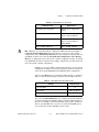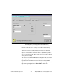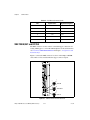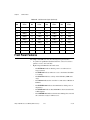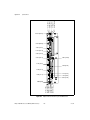
1
VXI
VXIpc 770/870B Series
User Manual (Online Version)
TM
VXIpc 770/870B Series User Manual (Online Version)
March 2002 Edition
Part Number 370381A-01
Support
Worldwide Technical Support and Product Information
ni.com
National Instruments Corporate Headquarters
11500 North Mopac Expressway
Austin, Texas 78759-3504
USA Tel: 512 683 0100
Worldwide Offices
Australia 03 9879 5166, Austria 0662 45 79 90 0, Belgium 02 757 00 20, Brazil 011 3262 3599,
Canada (Calgary) 403 274 9391, Canada (Montreal) 514 288 5722, Canada (Ottawa) 613 233 5949,
Canada (Québec) 514 694 8521, Canada (Toronto) 905 785 0085, China (Shanghai) 021 6555 7838,
China (ShenZhen) 0755 3904939, Czech Republic 02 2423 5774, Denmark 45 76 26 00, Finland 09 725 725 11,
France 01 48 14 24 24, Germany 089 741 31 30, Greece 30 1 42 96 427, Hong Kong 2645 3186,
India 91 80 535 5406, Israel 03 6393737, Italy 02 413091, Japan 03 5472 2970, Korea 02 3451 3400,
Malaysia 603 9596711, Mexico 001 800 010 0793, Netherlands 0348 433466, New Zealand 09 914 0488,
Norway 32 27 73 00, Poland 0 22 3390 150, Portugal 351 210 311 210, Russia 095 238 7139,
Singapore 2265886, Slovenia 386 3 425 4200, South Africa 11 805 8197, Spain 91 640 0085,
Sweden 08 587 895 00, Switzerland 056 200 51 51, Taiwan 02 2528 7227, United Kingdom 01635 523545
For further support information, see the Technical Support and Professional Services appendix. To comment on
the documentation, send email to [email protected].
© 2002 National Instruments Corporation. All rights reserved.
Important Information
Warranty
The VXIpc-770 and VXIpc 870B Series embedded VXI computers are warranted against defects in materials and workmanship for a period of
one year from the date of shipment, as evidenced by receipts or other documentation. National Instruments will, at its option, repair or replace
equipment that proves to be defective during the warranty period. This warranty includes parts and labor.
The media on which you receive National Instruments software are warranted not to fail to execute programming instructions, due to defects
in materials and workmanship, for a period of 90 days from date of shipment, as evidenced by receipts or other documentation. National
Instruments will, at its option, repair or replace software media that do not execute programming instructions if National Instruments receives
notice of such defects during the warranty period. National Instruments does not warrant that the operation of the software shall be
uninterrupted or error free.
A Return Material Authorization (RMA) number must be obtained from the factory and clearly marked on the outside of the package before
any equipment will be accepted for warranty work. National Instruments will pay the shipping costs of returning to the owner parts which are
covered by warranty.
National Instruments believes that the information in this document is accurate. The document has been carefully reviewed for technical
accuracy. In the event that technical or typographical errors exist, National Instruments reserves the right to make changes to subsequent
editions of this document without prior notice to holders of this edition. The reader should consult National Instruments if errors are suspected.
In no event shall National Instruments be liable for any damages arising out of or related to this document or the information contained in it.
EXCEPT AS SPECIFIED HEREIN, NATIONAL INSTRUMENTS MAKES NO WARRANTIES, EXPRESS OR IMPLIED, AND SPECIFICALLY DISCLAIMS ANY WARRANTY OF
MERCHANTABILITY OR FITNESS FOR A PARTICULAR PURPOSE. CUSTOMER’S RIGHT TO RECOVER DAMAGES CAUSED BY FAULT OR NEGLIGENCE ON THE PART OF
NATIONAL INSTRUMENTS SHALL BE LIMITED TO THE AMOUNT THERETOFORE PAID BY THE CUSTOMER. NATIONAL INSTRUMENTS WILL NOT BE LIABLE FOR
DAMAGES RESULTING FROM LOSS OF DATA, PROFITS, USE OF PRODUCTS, OR INCIDENTAL OR CONSEQUENTIAL DAMAGES, EVEN IF ADVISED OF THE POSSIBILITY
THEREOF. This limitation of the liability of National Instruments will apply regardless of the form of action, whether in contract or tort, including
negligence. Any action against National Instruments must be brought within one year after the cause of action accrues. National Instruments
shall not be liable for any delay in performance due to causes beyond its reasonable control. The warranty provided herein does not cover
damages, defects, malfunctions, or service failures caused by owner’s failure to follow the National Instruments installation, operation, or
maintenance instructions; owner’s modification of the product; owner’s abuse, misuse, or negligent acts; and power failure or surges, fire,
flood, accident, actions of third parties, or other events outside reasonable control.
Copyright
Under the copyright laws, this publication may not be reproduced or transmitted in any form, electronic or mechanical, including photocopying,
recording, storing in an information retrieval system, or translating, in whole or in part, without the prior written consent of National
Instruments Corporation.
Trademarks
CVI™, LabVIEW™, MITE™, National Instruments™, NI™, NI-488.2™, NI-488.2M™, ni.com™, NI-DAQ™, NI-VISA™, NI-VXI™ , and VXIpc™
are trademarks of National Instruments Corporation.
Product and company names mentioned herein are trademarks or trade names of their respective companies.
Patents
For patents covering National Instruments products, refer to the appropriate location: Help»Patents in your software, the patents.txt file
on your CD, or ni.com/patents.
WARNING REGARDING USE OF NATIONAL INSTRUMENTS PRODUCTS
(1) NATIONAL INSTRUMENTS PRODUCTS ARE NOT DESIGNED WITH COMPONENTS AND TESTING FOR A LEVEL OF
RELIABILITY SUITABLE FOR USE IN OR IN CONNECTION WITH SURGICAL IMPLANTS OR AS CRITICAL COMPONENTS IN
ANY LIFE SUPPORT SYSTEMS WHOSE FAILURE TO PERFORM CAN REASONABLY BE EXPECTED TO CAUSE SIGNIFICANT
INJURY TO A HUMAN.
(2) IN ANY APPLICATION, INCLUDING THE ABOVE, RELIABILITY OF OPERATION OF THE SOFTWARE PRODUCTS CAN BE
IMPAIRED BY ADVERSE FACTORS, INCLUDING BUT NOT LIMITED TO FLUCTUATIONS IN ELECTRICAL POWER SUPPLY,
COMPUTER HARDWARE MALFUNCTIONS, COMPUTER OPERATING SYSTEM SOFTWARE FITNESS, FITNESS OF COMPILERS
AND DEVELOPMENT SOFTWARE USED TO DEVELOP AN APPLICATION, INSTALLATION ERRORS, SOFTWARE AND
HARDWARE COMPATIBILITY PROBLEMS, MALFUNCTIONS OR FAILURES OF ELECTRONIC MONITORING OR CONTROL
DEVICES, TRANSIENT FAILURES OF ELECTRONIC SYSTEMS (HARDWARE AND/OR SOFTWARE), UNANTICIPATED USES OR
MISUSES, OR ERRORS ON THE PART OF THE USER OR APPLICATIONS DESIGNER (ADVERSE FACTORS SUCH AS THESE ARE
HEREAFTER COLLECTIVELY TERMED “SYSTEM FAILURES”). ANY APPLICATION WHERE A SYSTEM FAILURE WOULD
CREATE A RISK OF HARM TO PROPERTY OR PERSONS (INCLUDING THE RISK OF BODILY INJURY AND DEATH) SHOULD
NOT BE RELIANT SOLELY UPON ONE FORM OF ELECTRONIC SYSTEM DUE TO THE RISK OF SYSTEM FAILURE. TO AVOID
DAMAGE, INJURY, OR DEATH, THE USER OR APPLICATION DESIGNER MUST TAKE REASONABLY PRUDENT STEPS TO
PROTECT AGAINST SYSTEM FAILURES, INCLUDING BUT NOT LIMITED TO BACK-UP OR SHUT DOWN MECHANISMS.
BECAUSE EACH END-USER SYSTEM IS CUSTOMIZED AND DIFFERS FROM NATIONAL INSTRUMENTS' TESTING
PLATFORMS AND BECAUSE A USER OR APPLICATION DESIGNER MAY USE NATIONAL INSTRUMENTS PRODUCTS IN
COMBINATION WITH OTHER PRODUCTS IN A MANNER NOT EVALUATED OR CONTEMPLATED BY NATIONAL
INSTRUMENTS, THE USER OR APPLICATION DESIGNER IS ULTIMATELY RESPONSIBLE FOR VERIFYING AND VALIDATING
THE SUITABILITY OF NATIONAL INSTRUMENTS PRODUCTS WHENEVER NATIONAL INSTRUMENTS PRODUCTS ARE
INCORPORATED IN A SYSTEM OR APPLICATION, INCLUDING, WITHOUT LIMITATION, THE APPROPRIATE DESIGN,
PROCESS AND SAFETY LEVEL OF SUCH SYSTEM OR APPLICATION.
Compliance
FCC/Canada Radio Frequency Interference Compliance*
Determining FCC Class
The Federal Communications Commission (FCC) has rules to protect wireless communications from interference. The FCC
places digital electronics into two classes. These classes are known as Class A (for use in industrial-commercial locations only)
or Class B (for use in residential or commercial locations). Depending on where it is operated, this product could be subject to
restrictions in the FCC rules. (In Canada, the Department of Communications (DOC), of Industry Canada, regulates wireless
interference in much the same way.)
Digital electronics emit weak signals during normal operation that can affect radio, television, or other wireless products. By
examining the product you purchased, you can determine the FCC Class and therefore which of the two FCC/DOC Warnings
apply in the following sections. (Some products may not be labeled at all for FCC; if so, the reader should then assume these are
Class A devices.)
FCC Class A products only display a simple warning statement of one paragraph in length regarding interference and undesired
operation. Most of our products are FCC Class A. The FCC rules have restrictions regarding the locations where FCC Class A
products can be operated.
FCC Class B products display either a FCC ID code, starting with the letters EXN,
or the FCC Class B compliance mark that appears as shown here on the right.
Consult the FCC Web site at http://www.fcc.gov for more information.
FCC/DOC Warnings
This equipment generates and uses radio frequency energy and, if not installed and used in strict accordance with the instructions
in this manual and the CE Mark Declaration of Conformity**, may cause interference to radio and television reception.
Classification requirements are the same for the Federal Communications Commission (FCC) and the Canadian Department
of Communications (DOC).
Changes or modifications not expressly approved by National Instruments could void the user’s authority to operate the
equipment under the FCC Rules.
Class A
Federal Communications Commission
This equipment has been tested and found to comply with the limits for a Class A digital device, pursuant to part 15 of the FCC
Rules. These limits are designed to provide reasonable protection against harmful interference when the equipment is operated
in a commercial environment. This equipment generates, uses, and can radiate radio frequency energy and, if not installed and
used in accordance with the instruction manual, may cause harmful interference to radio communications. Operation of this
equipment in a residential area is likely to cause harmful interference in which case the user will be required to correct
the interference at his own expense.
Canadian Department of Communications
This Class A digital apparatus meets all requirements of the Canadian Interference-Causing Equipment Regulations.
Cet appareil numérique de la classe A respecte toutes les exigences du Règlement sur le matériel brouilleur du Canada.
Class B
Federal Communications Commission
This equipment has been tested and found to comply with the limits for a Class B digital device, pursuant to part 15 of the
FCC Rules. These limits are designed to provide reasonable protection against harmful interference in a residential installation.
This equipment generates, uses, and can radiate radio frequency energy and, if not installed and used in accordance with the
instructions, may cause harmful interference to radio communications. However, there is no guarantee that interference will not
occur in a particular installation. If this equipment does cause harmful interference to radio or television reception, which can
be determined by turning the equipment off and on, the user is encouraged to try to correct the interference by one or more of
the following measures:
• Reorient or relocate the receiving antenna.
• Increase the separation between the equipment and receiver.
• Connect the equipment into an outlet on a circuit different from that to which the receiver is connected.
• Consult the dealer or an experienced radio/TV technician for help.
Canadian Department of Communications
This Class B digital apparatus meets all requirements of the Canadian Interference-Causing Equipment Regulations.
Cet appareil numérique de la classe B respecte toutes les exigences du Règlement sur le matériel brouilleur du Canada.
Compliance to EU Directives
Readers in the European Union (EU) must refer to the Manufacturer’s Declaration of Conformity (DoC) for information**
pertaining to the CE Mark compliance scheme. The Manufacturer includes a DoC for most every hardware product except for
those bought for OEMs, if also available from an original manufacturer that also markets in the EU, or where compliance is not
required as for electrically benign apparatus or cables.
To obtain the DoC for this product, click Declaration of Conformity at ni.com/hardref.nsf/. This Web site lists the DoCs
by product family. Select the appropriate product family, followed by your product, and a link to the DoC appears in Adobe
Acrobat format. Click the Acrobat icon to download or read the DoC.
* Certain exemptions may apply in the USA, see FCC Rules §15.103 Exempted devices, and §15.105(c). Also available in
sections of CFR 47.
** The CE Mark Declaration of Conformity will contain important supplementary information and instructions for the user or
installer.
Contents
About This Manual
How to Use the Documentation Set...............................................................................xi
Conventions ...................................................................................................................xi
Related Documentation..................................................................................................xii
Chapter 1
Introduction
VXIpc 770/870B Series Overview ................................................................................1-1
Description ......................................................................................................1-1
Modules ...........................................................................................................1-1
VXIpc 770/870B Series Functional Block Diagram .......................................1-2
VXIpc 770/870B Series Functional Description.............................................1-3
National Instruments Software ......................................................................................1-4
Chapter 2
Installation
Installing the VXIpc 770/870B Series ...........................................................................2-1
How to Remove the Controller from the VXI Chassis....................................2-3
Removing the VXIpc 770/870B Series Component Side Cover ...................................2-4
Installing and Upgrading RAM .....................................................................................2-4
Installing a PCI Card (VXIpc-872B Only) ....................................................................2-5
Installing and Removing the Internal Hard Drive .........................................................2-5
Chapter 3
Configuration and Default Settings
Hardware Default Settings.............................................................................................3-1
System CMOS .................................................................................................3-2
SCSI Termination............................................................................................3-3
Hard Drive Jumper ..........................................................................................3-3
Slot 0 Detection/System Controller.................................................................3-4
MITE EEPROM ..............................................................................................3-5
Power-On Self Configuration ...........................................................3-5
User/Factory Configuration ..............................................................3-5
How to Fix an Invalid EEPROM Configuration...............................3-6
CLK10 Source Routing and Termination........................................................3-7
© National Instruments Corporation
vii
VXIpc 770/870B Series User Manual (Online Version)
Contents
BIOS Configuration....................................................................................................... 3-8
Entering BIOS Setup....................................................................................... 3-8
Main Setup Menu............................................................................................ 3-9
DMI Event Logging Submenu ......................................................... 3-9
Advanced Setup Menu .................................................................................... 3-10
Integrated Peripherals Submenu ....................................................... 3-11
Security Setup Menu ....................................................................................... 3-12
Boot Setup Menu ............................................................................................ 3-13
Exiting BIOS Setup......................................................................................... 3-13
Software Configuration ................................................................................................. 3-14
Measurement and Automation Explorer (MAX) ............................................ 3-14
Default MAX Settings ...................................................................... 3-14
VXI-MXI-2 Default Settings............................................................ 3-17
PCI-MXI-2 Default Settings............................................................. 3-19
Front Panel SMB ExtClk Setup ...................................................................... 3-20
Front Panel SMB TRGIN/TRGOUT .............................................................. 3-21
Watchdog Timer ............................................................................................. 3-21
Chapter 4
Developing Your Application
NI-VXI, NI-VISA, and Related Terms ......................................................................... 4-1
Configuration................................................................................................................. 4-2
Device Interaction ......................................................................................................... 4-3
Programming for VXI ................................................................................................... 4-6
Optimizing Large VXIbus Transfers .............................................................. 4-7
Shared Memory............................................................................................... 4-8
NI-VXI API Notes .......................................................................................... 4-8
Compiler Symbols ............................................................................ 4-8
Compatibility Layer Options ............................................................ 4-8
Debugging ..................................................................................................................... 4-9
Chapter 5
I/O Information
Front Panel Connectors ................................................................................................. 5-1
VGA ................................................................................................................ 5-3
COM1 and COM2........................................................................................... 5-5
Ethernet ........................................................................................................... 5-6
Parallel Port..................................................................................................... 5-8
Universal Serial Bus........................................................................................ 5-10
PS/2 ................................................................................................................. 5-11
SMB TRGIN/OUT and EXTCLK .................................................................. 5-12
VXIpc 770/870B Series User Manual (Online Version)
viii
ni.com
Contents
GPIB (IEEE 488.2)..........................................................................................5-13
SCSI.................................................................................................................5-15
Front Panel Features ......................................................................................................5-16
Data Storage...................................................................................................................5-17
Chapter 6
Common Questions and Troubleshooting
General Questions..........................................................................................................6-1
Operating System, Drivers, and Software .....................................................................6-1
Boot Options ..................................................................................................................6-4
Hard Drive Recovery .....................................................................................................6-4
Installing an OS .............................................................................................................6-7
Installing from a CD-ROM .............................................................................6-7
Installing from a Network ...............................................................................6-8
Cables, Optional Hardware, and Main Power Fuse.......................................................6-8
Troubleshooting .............................................................................................................6-10
Appendix A
Specifications
Appendix B
Modifying and Installing I/O Expansion Boards
Appendix C
Technical Support and Professional Services
Glossary
Index
© National Instruments Corporation
ix
VXIpc 770/870B Series User Manual (Online Version)
About This Manual
This manual contains detailed instructions for installing and
configuring your National Instruments VXIpc-770 or VXIpc 870B Series
embedded computer kit.
How to Use the Documentation Set
Begin by reading VXIpc 770/870B Series Installation and Troubleshooting,
a brief quick-start guide that describes how to install and get started with
your controller.
This manual, the VXIpc 770/870B Series User Manual (Online Version),
contains more details about changing the installation or configuration from
the defaults and using the hardware.
Conventions
The following conventions appear in this manual:
This icon denotes a note, which alerts you to important information.
This icon denotes a caution, which advises you of precautions to take to
avoid injury, data loss, or a system crash.
bold
Bold text denotes items that you must select or click on in the software,
such as menu items and dialog box options. Bold text also denotes
parameter names.
italic
Italic text denotes variables, emphasis, a cross reference, or an introduction
to a key concept. This font also denotes text that is a placeholder for a word
or value that you must supply.
monospace
Text in this font denotes text or characters that you should enter from the
keyboard, sections of code, programming examples, and syntax examples.
This font is also used for the proper names of disk drives, paths, directories,
programs, subprograms, subroutines, device names, functions, operations,
variables, filenames and extensions, and code excerpts.
© National Instruments Corporation
xi
VXIpc 770/870B Series User Manual (Online Version)
About This Manual
monospace bold
Bold text in this font denotes the messages and responses that the computer
automatically prints to the screen. This font also emphasizes lines of code
that are different from the other examples.
VXIpc 770/870B series
The terms VXIpc 770/870B Series refers to the VXIpc-770, VXIpc-871B,
and VXIpc-872B controllers, where the information applies to all
controllers.
Related Documentation
The following documents contain information you may find helpful as you
read this manual:
•
ANSI/IEEE Standard 1014-1987, IEEE Standard for a Versatile
Backplane Bus: VMEbus
•
ANSI/IEEE Standard 1155-1998, IEEE VMEbus Extensions for
Instrumentation: VXIbus
•
ANSI/VITA 1-1994, VME64
•
VXI-6, VXIbus Mainframe Extender Specification, Rev. 2.0,
VXIbus Consortium
•
NI-VISA User Manual
•
NI-VISA Programmer Reference Manual
VXIpc 770/870B Series User Manual (Online Version)
xii
ni.com
1
Introduction
VXIpc 770/870B Series Overview
Description
The VXIpc 770/870B Series embedded computers are high-performance
C-size VXIbus system controllers. Both series controllers use off-the-shelf
Intel PC technologies to bring you powerful VXI system control in a
familiar PC environment. Using state-of-the-art packaging, the VXIpc-770
provides flexible single-slot control for your instrumentation needs, while
the VXIpc 870B Series provides powerful control in a two-slot
configuration.
Install either of these VXIpc controllers in your VXI mainframe, and you
can take full advantage of the high-performance VXI backplane and have
direct control of VXI registers, memory, interrupts, and triggers.
The VXIpc 770/870B Series computers are fully VXIplug&play compliant
and compatible with PC-compatible software tools, the National
Instruments LabVIEW and LabWindows/CVI application software, and
the NI-VISA, NI-VXI, and NI-488.2 bus interface software.
Modules
The VXIpc 770/870B Series controllers are available in three different
configurations: the VXIpc-770, VXIpc-871B, and VXIpc-872B. All
module configurations share a standard I/O set that includes integrated
video, two PS/2 ports for keyboard and mouse, two USB ports, two RS-232
serial ports, one parallel port, 10/100 Ethernet, GPIB, three SMB
connectors for trigger and clock I/O, and a system reset button. The
controllers also include the Intel 815E chipset, which provides an interface
for a 2.5 in. ATA100 hard drive and support for up to 512 MB RAM.
The VXIpc-770 features an Intel Celeron processor.
The VXIpc 870 Series controllers include an Intel Pentium III processor,
a Wide Ultra2 SCSI port, two PC Card slots, and a computer speaker out
© National Instruments Corporation
1-1
VXIpc 770/870B Series User Manual (Online Version)
Chapter 1
Introduction
jack. The VXIpc-871B includes an integrated CD-ROM drive; the
VXIpc-872B includes a PCI expansion slot.
VXIpc 770/870B Series Functional Block Diagram
Figure 1-1 is a functional block diagram of the VXIpc 770/870B Series
controllers.
Socket
370
CPU
SO-DIMM
SDRAM
PC 133
PCI
Slot
Chip Set
Graphics
Memory
Controller
Hub
VGA
Connector
CardBus
Hub Interface
ATA 100
IDE Interface
Wide Ultra2
SCSI
Chip Set
I/O
Controller
Hub
(ICH2)
2 USB
Connectors
10/100BaseT
Ethernet
PCI Bus
PCI
GPIB
Firmware
Hub
LPC Bus
VXI
Interface
LPT
COM 1,
COM 2
XBus
Watchdog
Super I/O
Internal
Floppy
External
Clock SMB
PS/2
VXI Trigger
OUT SMB
VXI Trigger
IN SMB
Keyboard/
Mouse
VXIpc-870B Only
VXIpc-872B Only
Figure 1-1. VXIpc 770/870B Series Block Diagram
VXIpc 770/870B Series User Manual (Online Version)
1-2
ni.com
Chapter 1
Introduction
VXIpc 770/870B Series Functional Description
This section contains brief functional descriptions of the major
VXIpc 770/870B logic blocks shown in Figure 1-1.
•
Socket 370 CPU is the socket definition for the Intel Pentium III and
Celeron processors used in the VXIpc 770/870B Series controllers.
•
The Chipset GMCH connects the CPU to the memory, I/O controller
hub, and video.
•
The SO-DIMM block consists of two 64-bit SDRAM sockets that can
hold up to 512 MB.
•
The Chipset ICH2 connects to the GMCH, PCI bus, LPC bus, IDE
interface, USB, and Ethernet.
•
The ATA100 IDE Interface block is a dedicated PCI-IDE interface
providing fast ATA100 transfers to an internal hard drive. The IDE
interface is integrated in the chipset.
For the VXIpc-871B only, a CD-ROM drive is connected to the
secondary IDE channel.
•
USB is also integrated in the chipset and provides two connections to
the Universal Serial Bus.
•
The 10/100 Ethernet autonegotiates its connection to either a 10 Mbit
or 100 Mbit Ethernet connection.
•
The Firmware Hub is a 4 Mbit Flash device for storing the system
BIOS.
•
The Super I/O block represents the other peripherals included with the
VXIpc 770/870B Series controllers, including:
–
Two serial ports
–
One parallel port
–
Two PS/2 ports
–
A Watchdog timer
You can program the Watchdog timer1 to reset the controller or
generate a trigger.
–
•
1
An internal 1.44 MB 3.5 in. floppy drive (VXIpc 870B Series
only)
The PCI GPIB block provides an interface to the NI-488.2 General
Purpose Interface Bus.
Currently, there is no software support for the Watchdog timer. If your application requires the watchdog timer, contact
National Instruments for detailed instructions on how to program this device.
© National Instruments Corporation
1-3
VXIpc 770/870B Series User Manual (Online Version)
Chapter 1
Introduction
•
The VXI Interface connects the VXIpc 770/870B Series controllers to
the VXI backplane through the National Instruments MITE ASIC.
•
The External Clock SMB provides an input for an external source to
generate CLK10 to the VXI backplane or allow you to output CLK10
to an external device.
•
The VXI Trigger In/Out SMBs provide a routable connection of the
VXI triggers to and from the VXI backplane.
The following blocks apply to the VXIpc 870B Series only.
•
The Wide Ultra2 SCSI provides a PCI-SCSI interface using the
LSI53C895A SCSI controller.
•
The CardBus block represents a PCI-CardBus interface using the
TIPCI-1450 CardBus host bus adapter.
•
The PCI Slot represents the PCI expansion slot available on the
VXIpc-872B.
National Instruments Software
National Instruments has developed several software kits you can use with
the VXIpc 770/870B Series. NI-VISA and NI-VXI are already installed on
your hard drive; LabVIEW is optional.
NI-VISA is the National Instruments implementation of the VISA
specification. VISA is a uniform API for communicating and controlling
Serial, GPIB, VXI, and VME instruments. This API aids in the creation of
more portable applications and instrument drivers.
NI-VXI is the name of the National Instruments VXI bus control library.
You can create applications using NI-VXI to control both VXI and VME
devices. NI-VXI gives you complete VXI/VME functionality, including
an API for performing basic VXI/VME data transfers and handling
VXI/VME interrupts as well as VXI-specific functionality, such as
doing message-based communication and handling VXIbus triggers.
The NI-VISA/NI-VXI software includes an interactive configuration and
troubleshooting program, libraries of software routines for test and
measurement (T&M) programming, interactive control programs for both
NI-VISA and NI-VXI, a logging utility you can use for debugging your
applications, and a VXI Resource Manager. You can use this software to
seamlessly program multiple-mainframe configurations and have software
compatibility across a variety of controller platforms.
VXIpc 770/870B Series User Manual (Online Version)
1-4
ni.com
Chapter 1
Introduction
You can also use the National Instruments LabVIEW application program
and instrument drivers to ease your programming task. This standardized
program matches the modular virtual instrument capability of VXI and can
reduce your VXI software development time. This program features
extensive libraries of GPIB, Serial, and VXI instrument drivers written to
take full advantage of direct VXI control. LabVIEW includes all the tools
needed for instrument control, data acquisition, analysis, and presentation.
LabVIEW is an easy-to-use, graphical programming environment you can
use to acquire data from thousands of different instruments, including
IEEE 488.2 devices, VXI devices, serial devices, PLCs, and plug-in data
acquisition boards. After you have acquired raw data, you can convert it
into meaningful results using the powerful data analysis routines in
LabVIEW. LabVIEW also comes with hundreds of instrument drivers,
which dramatically reduce software development time, because you do not
need to spend time programming the low-level control of each instrument.
© National Instruments Corporation
1-5
VXIpc 770/870B Series User Manual (Online Version)
2
Installation
This chapter contains information about installing your VXIpc 770/870B
Series controller and components.
Electrostatic discharge can damage your controller. To avoid such damage,
handle the controller only in a proper ESD-controlled environment.
Caution
Installing the VXIpc 770/870B Series
This section contains general installation instructions for the
VXIpc 770/870B Series controller. Consult your VXIbus chassis user
manual or technical reference manual for specific instructions and
warnings.
1.
Plug in your chassis before installing the controller. The power cord
grounds the chassis and protects it from electrical damage while you
are installing the controller.
To protect both yourself and the chassis from electrical hazards, the chassis
should remain off until you finish installing the controller.
Caution
2.
Remove or open any doors or covers blocking access to the chassis
slots.
If the controller is not configured for automatic System Controller detection, be
certain that the slot you select in your VXIbus chassis matches the controller configuration
as either a System Controller device or a Non-System Controller device. Installing the
controller into a slot that does not correspond with the jumper setting can damage the
controller, the VXIbus backplane, or both. See the Slot 0 Detection/System Controller
section in Chapter 3, Configuration and Default Settings, for jumper configuration
information.
Caution
3.
© National Instruments Corporation
Insert the controller in the desired slot by aligning the top and bottom
of the controller with the card-edge guides inside the chassis. Slowly
push the controller straight into the slot until its plug connectors are
resting on the backplane receptacle connectors. Using slow, evenly
distributed pressure, press the module straight in until it seats in the
2-1
VXIpc 770/870B Series User Manual (Online Version)
Chapter 2
Installation
expansion slot. The front panel of the controller should be even with
the front panel of the chassis.
4.
Tighten the retaining screws on the top and bottom edges of the front
panel.
5.
Check the installation.
6.
Connect the keyboard and mouse to the appropriate PS/2 connectors.
7.
Connect the VGA monitor video cable to the VGA connector.
8.
Connect devices to ports as required by your system configuration.
9.
Replace or close any doors or covers on the chassis.
10. Turn on the chassis.
11. The controller should now boot. If the controller does not boot, see
the What if the VXIpc 770/870B Series does not boot? section in
Chapter 6, Common Questions and Troubleshooting.
12. On the first boot of the controller, a setup program automatically runs.
13. Follow the prompts in the setup program to fully configure your
controller.
14. When prompted for the Windows serial number, enter the serial
number of the operating system from the included certificate.
15. Your controller is now ready for development.
Figure 2-1 shows a VXIpc-872B installed in the system controller slot of a
National Instruments VXI chassis. You can place VXI devices in any other
slot.
VXIpc 770/870B Series User Manual (Online Version)
2-2
ni.com
Chapter 2
Installation
2
1
1
VXIpc-872B Controller
2
VXI Chassis
Figure 2-1. VXIpc-872B Controller Installed in a VXI Chassis
How to Remove the Controller from the VXI Chassis
The VXIpc 770/870B Series controllers are designed for easy handling.
To remove the controller from the VXI chassis:
1.
Shut down all applications and the operating system.
2.
Turn off power.
3.
Disconnect devices from the front panel ports as your system
configuration requires.
4.
Remove the retaining screws in the controller front panel.
5.
Push the upper ejector handle up and the lower ejector handle down
until the controller pops out of the backplane connectors.
6.
Slide the controller out of the chassis.
© National Instruments Corporation
2-3
VXIpc 770/870B Series User Manual (Online Version)
Chapter 2
Installation
Removing the VXIpc 770/870B Series Component
Side Cover
The VXIpc 770/870B Series is housed in a metal enclosure comprised of
a top and bottom cover to improve EMC performance and provide easy
handling. To access the jumper settings or install modules such as RAM or
PCI cards, you must remove the component side cover.
Remove the top cover by removing the screws that attach it to the module.
Installing and Upgrading RAM
The VXIpc 770/870B Series uses 144-pin 133 MHz SDRAM and supports
64, 128, 256, and 512 MB SO-DIMMs, for a maximum of 512 MB. There
are two RAM sockets in the VXIpc 770/870B Series, and you can change
the amount of installed RAM by upgrading the SO-DIMMs.
National Instruments recommends the following size SO-DIMMs for use
with the VXIpc 770/870B Series controller (SDRAM):
64 MB
128 MB
256 MB
4 MB × 64 SO-DIMMs—10 ns, 1.05 in. max.
8 MB × 64 SO-DIMMs—10 ns, 1.05 in. max.
16 MB × 64 SO-DIMMs—10 ns, 1.05 in. max.
National Instruments has tested and verified that the SO-DIMMs we sell work with
the VXIpc 770/870B Series. We recommend you purchase your SO-DIMM modules from
National Instruments. Other off-the-shelf SO-DIMM modules are not guaranteed to work
properly.
Note
To add or replace RAM for the VXIpc 770/870B Series, follow these steps:
1.
Remove the VXIpc 770/870B Series from the chassis. See the removal
instructions in the How to Remove the Controller from the VXI Chassis
section.
2.
Remove the component side cover. See the removal instructions in the
Removing the VXIpc 770/870B Series Component Side Cover section.
3.
Add the SO-DIMM modules to the empty SO-DIMM sockets.
See Figure 2-2.
To ensure proper memory operation with a single-SO-DIMM configuration, always
populate slot XA2. For a two-SO-DIMM configuration, populate slot XA2 with the higher
capacity SO-DIMM.
Note
VXIpc 770/870B Series User Manual (Online Version)
2-4
ni.com
Chapter 2
Installation
3
2
1
1
SO-DIMM Socket XA1
2
SO-DIMM Module
3
SO-DIMM Socket XA2
Figure 2-2. Installing a SO-DIMM in an VXIpc 770/870B Series Controller
Installing a PCI Card (VXIpc-872B Only)
The VXIpc-872B has a single PCI expansion slot. See Appendix B,
Modifying and Installing I/O Expansion Boards, for PCI board installation
instructions.
Installing and Removing the Internal Hard Drive
Follow these steps to remove the internal hard drive from your
VXIpc 770/870B Series controller:
1.
Remove the controller from the chassis. See the removal instructions
in the How to Remove the Controller from the VXI Chassis section.
2.
Remove the component side cover. See the removal instructions in the
Removing the VXIpc 770/870B Series Component Side Cover section.
3.
Remove the four screws under the solder side cover that hold the hard
drive in place.
4.
Carefully and slowly slide the hard drive toward the rear of the
controller to free the pins from the IDE connector.
© National Instruments Corporation
2-5
VXIpc 770/870B Series User Manual (Online Version)
Chapter 2
Installation
Be careful when sliding the hard drive toward the rear of the controller. The hard
drive could contact components on the motherboard, causing severe damage to both the
components and motherboard.
Caution
5.
When the pins are free of the connector, lift the hard drive off the
motherboard.
Always handle the hard drive in accordance with the handling instructions outlined
by the hard drive manufacturer.
Note
Follow these steps to install the internal hard drive in your VXIpc 770/870B
Series controller:
1.
Be sure the insulating pad is properly placed on the motherboard over
the hard drive ground plane.
2.
Set the hard drive on the motherboard and carefully slide the drive
forward until it seats firmly in the IDE connector. The insulating pad
should be between the hard drive and the motherboard.
Use care when installing the hard drive. The rear of the hard drive could contact
components on the motherboard, causing severe damage to both the components and
motherboard.
Caution
3.
Reinstall the four screws that hold the hard drive in place.
4.
Reinstall the component side cover.
The controller is now ready to be reinstalled in the VXI mainframe.
VXIpc 770/870B Series User Manual (Online Version)
2-6
ni.com
Configuration and Default Settings
3
Hardware Default Settings
This chapter summarizes the hardware default settings for the
VXIpc 770/870B Series for easy reference. The module is set at the
factory for the most commonly used configuration.
Figure 3-1 shows the location of the user-configurable jumpers and
switches on the VXIpc 770/870B Series. The diagram also shows the
location of the serial number and assembly numbers.
7
6
5
1
1
2
3
CMOS (W5)
SCSI Termination Enable (W6)
Hard Drive Master/Slave (J20)
2
4
5
4
3
Automatic Slot Detection (J17)
6
MITE Configuration Enable (W2) 7
MITE User Configuration (W1)
CLK10 Source Switch (S1)
Figure 3-1. VXIpc 770/870B Series Parts Locator Diagram
© National Instruments Corporation
3-1
VXIpc 770/870B Series User Manual (Online Version)
Chapter 3
Configuration and Default Settings
Table 3-1 lists the factory-default settings and options for the onboard
jumpers and switches.
Table 3-1. VXIpc 770/870B Series Hardware Default Settings
Jumper
Default Setting
Optional Setting
W5
1-2 Normal CMOS
operation
2-3 Clear CMOS
W6
2-3 16-bit SCSI
termination enabled
1-2 SCSI termination
disabled
J20
No jumper
Master/Slave/CSEL*
J17
3-4 Automatic slot zero
detection
1-2 Non-slot zero
W2
2-3 Enable MITE self
configuration
1-2 Disable MITE self
configuration
W1
2-3 MITE user
configuration
1-2 MITE factory
configuration
S1
1-2 Internal oscillator
2-3 External oscillator
5-6 Force slot zero
*These pins are generally defined in a figure on the hard drive cover.
Note Do not adjust any jumpers or switches not listed in Table 3-1 or that are not
documented in this manual unless directed by National Instruments. Other configuration
jumpers are shown in the event National Instruments technical support needs to make
adjustments to your settings.
System CMOS
The VXIpc 770/870B Series contains a battery backed-up memory used
to store BIOS configuration information. The battery is a hermetically
sealed lithium battery. Contact National Instruments technical support at
ni.com/support for more information about the battery.
To clear the CMOS contents:
1.
Follow the instructions in the How to Remove the Controller from the
VXI Chassis section of Chapter 2, Installation, to remove the controller
from the VXI chassis.
2.
Follow the instructions in the Removing the VXIpc 770/870B Series
Component Side Cover section of Chapter 2, Installation, to remove
the controller’s component side cover.
VXIpc 770/870B Series User Manual (Online Version)
3-2
www.ni.com
Chapter 3
Caution
Configuration and Default Settings
3.
Move the jumper on W5 from pins 1–2 to pins 2–3 as shown in
Figure 3-2.
4.
Wait 1 second. Move the jumper back to pins 1–2.
5.
Reinstall the controller in the chassis.
Do not leave the jumper on pins 2–3. Doing so decreases battery life.
W5
W5
a. Normal Operation
(Default)
b. Clear CMOS
Contents
Figure 3-2. System CMOS
SCSI Termination
The VXIpc 870B Series uses active termination on the Wide Ultra2 SCSI
bus. Because the VXIpc 870B Series is normally an end device, you should
not need to disable the termination; however, for informational purposes
Figure 3-3 shows the jumper settings for both enabled and disabled
termination.
W6
W6
a. Terminate SCSI
Signals (Default)
b. Do Not Terminate
SCSI Signals
Figure 3-3. SCSI Termination
Hard Drive Jumper
J20 provides easy access to the 2.5 in. IDE hard drive configuration pins.
Because most hard drives are device 0 by default, there should be no need
to install any jumpers on J20. However, some third-party drives require a
jumper to set the drive as device 0; therefore, you have access to the pins.
The jumper settings can be specific to the hard drive, and a diagram
showing the proper configurations is normally included with or on the hard
drive.
© National Instruments Corporation
3-3
VXIpc 770/870B Series User Manual (Online Version)
Chapter 3
Configuration and Default Settings
C
A
D
B
J20
Figure 3-4. Primary IDE Channel Configuration Jumper
Slot 0 Detection/System Controller
The VXIpc 770/870B Series is configured at the factory to automatically
detect if it is installed in Slot 0 of a VXIbus mainframe. With automatic
System Controller slot detection, you can install the module into any
VXIbus slot.
You can manually configure the VXIpc 770/870B Series for either System
Controller or Non-System Controller operation by defeating the
automatic-detection circuitry. Use the three-position jumper J17 to select
automatic detection, System Controller, or Non-System Controller
operation. Figure 3-5 shows these three settings.
Caution Do not install a device configured for System Controller into another slot
without first reconfiguring it to either Non-System Controller or automatic-detection
configuration. Neglecting to do this could result in damage to the device, the VXIbus
backplane, or both.
J17
J17
a. Manual Slot 0
Configuration
b. Automatic Slot 0
Detection (Default)
J17
c. Manual Non-Slot 0
Configuration
Figure 3-5. System Controller Slot Configuration
When the VXIpc 770/870B Series is installed in Slot 0 of a VXI system, it
becomes the VXIbus System Controller. In this role, it has VXIbus Data
Transfer Bus Arbiter circuitry that accepts bus requests on all four VXIbus
request levels, prioritizes the requests, and grants the bus to the highest
priority requester. As VXIbus System Controller, the VXIpc 770/870B
VXIpc 770/870B Series User Manual (Online Version)
3-4
www.ni.com
Chapter 3
Configuration and Default Settings
Series also drives the 16 MHz VXIbus system clock by an onboard 16 MHz
oscillator.
As required by the VXIbus specification, the VXIpc 770/870B Series
drives the 10 MHz signal CLK10 on a differential ECL output when
installed in Slot 0. When not installed in Slot 0, the VXIpc 770/870B Series
only receives the CLK10 signal.
MITE EEPROM
Power-On Self Configuration
The VXIpc 770/870B Series has an onboard EEPROM, which stores
default register values for the VXI circuitry. These values are loaded when
you power up the computer. The values read from the EEPROM program
the PCI interface and the VXIbus registers so that the VXI interface is ready
to respond to Resource Manager accesses within the required 5 s of
SYSRST# deasserting.
You can disable this power-on self-configuration (POSC) circuit by
changing switch W2. Although this makes the VXI circuitry unusable,
it is sometimes helpful in debugging address and interrupt conflicts with
add-in boards. In general, however, you should leave switch S2 in its
factory-default setting. Figure 3-6 shows the possible configurations
for W2.
W2
W2
a. VXI Circuitry Loads Power-on
Defaults from EEPROM (Default)
b. Power-on Self Configuration
Circuit is Disabled
Figure 3-6. Power-on Self Configuration Status
User/Factory Configuration
The EEPROM is divided into two halves—one half is factory configured
and one half is user configurable. Use jumper W1 to control the operation
of the EEPROM. The setting of this jumper determines whether the
VXIpc 770/870B Series boots off the factory-configured half or the
user-modified settings. In its default setting, the VXIpc 770/870B Series
boots off the user-configurable half.
© National Instruments Corporation
3-5
VXIpc 770/870B Series User Manual (Online Version)
Chapter 3
Configuration and Default Settings
This jumper is useful in the event that the user-configured half of the
EEPROM becomes corrupted in such a way that the VXIpc 770/870B
Series boots to an unusable state. By altering this jumper setting, you can
return to the factory configuration and get up and running again. Use the
procedure as described in the following section, How to Fix an Invalid
EEPROM Configuration.
Figure 3-7 shows the configuration settings for EEPROM operation.
W1
W1
a. Boot from User
Configuration (Default)
b. Boot from Protected
Configuration
Figure 3-7. EEPROM Configuration
How to Fix an Invalid EEPROM Configuration
Use MAX under Windows to edit the VXIpc 770/870B Series
configuration. Some of these settings are stored in files that the NI-VXI
software reads, while other settings are stored directly in the
VXIpc 770/870B Series EEPROM.
Certain EEPROM configurations, including invalid configurations, can
lock up your computer while it is booting. Generally, only the size and
location of the memory windows can cause your VXIpc 770/870B Series
to lock up your system. For example, many PCI-based computers will not
boot if a board in its system requests more memory space than the computer
can allocate. If you encounter this situation, you should reduce the size of
the VXIpc 770/870B Series user window. The EEPROM can become
corrupted if the VXIpc 770/870B Series is shut down while it is updating
the EEPROM.
If one of these situations occurs after you change the configuration, follow
these steps to reconfigure the VXIpc 770/870B Series:
1.
Turn off your computer.
To protect both yourself and the mainframe from electrical hazards,
the mainframe should remain off until you finish changing the settings on
the VXIpc 770/870B Series.
Caution
VXIpc 770/870B Series User Manual (Online Version)
3-6
www.ni.com
Chapter 3
Configuration and Default Settings
2.
Change jumper W1 to the position shown in Figure 3-7b to restore the
factory configuration.
3.
Turn on the computer. The computer should boot this time because the
factory-default configuration is being used to initialize the
VXIpc 770/870B Series.
4.
Run your software configuration utility to re-adjust the
VXIpc 770/870B Series configuration.
5.
After saving the configuration, exit Windows and turn off the
computer.
6.
Change jumper W1 to the default position, as shown in Figure 3-7a.
7.
Turn on the computer. If the computer does not boot with this
configuration, you will need to repeat these steps, modifying your
configuration until a final configuration is reached.
CLK10 Source Routing and Termination
When the VXIpc 770/870B Series is installed in Slot 0 of your mainframe,
it supplies the VXIbus CLK10 signal. The VXIpc 770/870B Series can use
two different sources to generate this signal—an onboard oscillator or an
external oscillator connected through the CLK SMB connector. You can
select the internal or external clock source by setting switch S1 as shown in
Table 3-1. The VXIpc 770/870B Series can also be configured to drive the
external CLK10 SMB with the VXIbus CLK10 signal. Use the hardware
configuration in MAX to route the CLK10 signal to the SMB connector.
A 50 Ω termination option is available in MAX to terminate an external
CLK10 source. The 50 Ω termination option has no effect when the internal
oscillator is selected as the CLK10 source.
1 2 3
1 2 3
S1
S1
a. CLK10 Source =
Internal Oscillator
b. CLK10 Source =
External Oscillator
Figure 3-8. SCSI Termination
Table 3-1 and Figure 3-8 are in agreement. Figure 3-8a shows the switch position for
shorting pins 1 and 2. Figure 3-8b shows the switch position for shorting pins 2 and 3.
Note
© National Instruments Corporation
3-7
VXIpc 770/870B Series User Manual (Online Version)
Chapter 3
Configuration and Default Settings
BIOS Configuration
You can change the VXIpc 770/870B Series configuration settings in the
BIOS setup. The BIOS is the low-level interface between the hardware and
PC software that configures and tests your hardware when you boot the
system. The BIOS setup program includes menus for configuring settings
and enabling controller features.
Most users do not need to use the BIOS setup program, as the
VXIpc 770/870B Series controller ships with default settings that
work well for most configurations.
Changing BIOS settings may lead to incorrect controller behavior and possibly
an unbootable controller. If this happens, follow the instructions for restoring default
settings in the System CMOS section. In general, do not change a setting unless you are
absolutely certain what it does.
Caution
Entering BIOS Setup
To start the BIOS setup utility:
1.
Turn on or reboot your VXIpc 770/870B Series controller.
2.
When the message Press <DEL> to enter SETUP appears, press
<Delete> or <Del> on the numeric keypad. The message Entering
Setup appears, and the setup program is loaded after a short delay.
3.
When you first enter the BIOS setup program, it displays the Main
menu.
Use the following keys to navigate through the BIOS setup:
•
Left Arrow, Right Arrow—Use these keys to move between the
different setup menus. If you are in a submenu, these keys have no
effect, and you need to press <Esc> to leave the submenu first. (To use
the arrows on the numeric keypad, you must turn off Num Lock.)
•
Up Arrow, Down Arrow—Use these keys to move between the
options within a setup menu. (To use the arrows on the numeric
keypad, you must turn off Num Lock.)
•
<Enter>—Use this key to either enter a submenu or display all
available settings for a highlighted configuration option.
•
<Esc>—Use this key to return the parent menu of a submenu. At the
top-level menus, this key serves as a shortcut to the Exit menu.
•
<+> and <–>—Use these keys to cycle between all available settings
for a selected configuration option.
VXIpc 770/870B Series User Manual (Online Version)
3-8
www.ni.com
Chapter 3
Configuration and Default Settings
Main Setup Menu
The most commonly accessed and modified BIOS settings are in the Main
setup menu. The Main setup menu includes the following settings:
•
System Time & Date—This setting controls the time of day, which is
stored in a battery-backed real-time clock. Most operating systems
also include a way to change this setting. Use <+> and <–> in
conjunction with <Enter> to change these values.
•
DMI Event Logging—This setting brings up the DMI Event
Logging submenu (see the DMI Event Logging Submenu section).
•
Keyboard Required to Boot—When Yes, a missing or
malfunctioning keyboard causes the BIOS to halt with an error. When
No, the BIOS allows booting without a keyboard, and you can attach a
keyboard at any time during the powered up state. To use this controller
in a “headless” mode, you must set this option to No. The default value
is Yes.
•
Num Lock—This setting indicates whether you turn on Num Lock at
boot time. The default value is On.
•
Primary/Secondary Master/Slave—These items display the
IDE/ATA devices detected in the system. Normally, you do not need to
modify these items. However, if an IDE/ATA device is not
autodetected properly, you can specify it manually by pressing
<Enter> on an item.
•
System Information—This setting displays a screen containing
important system information about the controller.
DMI Event Logging Submenu
Major errors that occur during the BIOS booting process are stored in
battery-backed memory on the controller and remain there until you view
and clear them using this submenu. This logging capability allows a system
administrator to detect the historical occurrence of faults on a controller.
This submenu includes the following items:
•
View DMI Event Log—This setting displays a window containing all
logged system errors and the time at which they occurred.
•
Mark Events as Read—This setting prevents any current logged
entries from being displayed again. However, all entries remain in
battery-backed memory, and you can retrieve them using other DMI
software that is beyond the scope of this document.
•
Clear All Events—When set to Yes, this setting clears all entries from
the DMI event log on reboot.
© National Instruments Corporation
3-9
VXIpc 770/870B Series User Manual (Online Version)
Chapter 3
Configuration and Default Settings
•
Event Logging—This setting controls whether events are logged.
Disabling logging has no impact on system performance. The default
is Enabled.
Advanced Setup Menu
This menu contains BIOS settings that normally do not require
modification. If you have specific problems such as unbootable disks or
resource conflicts, you may need to examine these settings.
Changing settings in this menu may result in an unstable or unbootable controller.
If this happens, follow the procedures outlined in the System CMOS section to restore
BIOS settings to their factory defaults.
Caution
The Advanced setup menu includes the following settings:
•
Reset Configuration Data—A portion of the EEPROM on the
controller is designated as the Extended System Configuration Data
region (ESCD). The BIOS and Plug-and-Play operating systems use
this table to store the Last Known Good configuration of system
peripherals. If you experience resource conflicts or peripheral
malfunction, set this setting to Yes to force the BIOS to recreate the
ESCD on the next reboot. This is rarely necessary.
•
Integrated Peripherals—Use this setting to bring up the Integrated
Peripherals submenu (see the Integrated Peripherals Submenu
section).
•
Local Bus IDE Adapter—The VXIpc 770/870B Series controller has
two integrated IDE/ATA channels (Primary and Secondary), each
capable of supporting two ATA devices (Master and Slave). Use this
setting to disable one or more of these integrated channels. You should
modify this setting only if specified in other sections of this manual.
The default is Both.
•
Write Protect Boot Sector—When set to Yes, this setting prevents
modification of a hard disk boot sector via INT 13h services, which
may help prevent certain computer viruses from infecting the
controller. This setting does not prevent boot sector modification by
32-bit operating system drivers that access the hard disk directly.
The default is No.
•
Quick Boot Mode—When you enable this option, certain lengthy
BIOS tests that rarely fail are skipped to shorten controller boot time.
The default is Enabled.
VXIpc 770/870B Series User Manual (Online Version)
3-10
www.ni.com
Chapter 3
Configuration and Default Settings
•
Summary Screen—This setting controls the display of the summary
screen shown after BIOS completes its initialization, but before
booting takes place. You can disable this screen in the interest of
shortening controller boot time. The default is Disabled.
•
PXE Network Boot—Setting this option to Enabled executes an
option ROM that allows booting a controller from the integrated
network connection via the PXE (Preboot eXecution Environment)
protocol. After setting this option, you may need to reboot, re-enter
BIOS Setup, and rearrange the items under the Boot menu for network
booting to take precedence over floppy drives and hard drives. The
default is Disabled.
•
SCSI Option ROM (VXIpc 870B only)—To boot from an SCSI
device attached to the integrated SCSI bus, set this option to
Enabled. This results in the BIOS running the SCSI Option ROM.
Unnecessarily enabling this option results in increased boot time. You
do not need to enable this option unless you want to boot from an SCSI
device. The default is Disabled.
Because of limited available memory for Option ROM mapping, you must enable
either PXE Network Boot or the SCSI Option ROM. Enabling both results in an
Expansion ROM error on the next boot.
Note
Integrated Peripherals Submenu
Use this submenu to apply nondefault configurations to the front panel
peripherals of an VXIpc 770/870B Series controller. Normally, you do not
need to modify these settings, as the factory default settings provide the
most compatible and optimal configuration possible.
•
Serial Port A & B—This setting enables or disables COM1 and
COM2, respectively. You can also change this setting to Enabled and
modify the base address and Interrupt Request Level (IRQ) of a port.
The default is Auto, which places COM1 at 0x3F8 IRQ 4 and COM2
at 0x2F8 IRQ 3.
•
Parallel Port—Use this setting to enable or disable LPT1. You can
also change this setting to Enabled and modify the base address, IRQ
level, and ISA Direct Memory Access (DMA) channel of the port. The
default is Auto, which places LPT1 at 0x378, IRQ 7, using ISA DMA
Channel 3 if necessary.
•
Parallel Port Mode—The PC industry has created several different
modes of operation for this port over the years. Usually, the default
setting works for all applications. However, if a parallel port device
specifically requires a nondefault setting, you can change it here.
The default is Bidirectional, for full IEEE 1284 capabilities.
© National Instruments Corporation
3-11
VXIpc 770/870B Series User Manual (Online Version)
Chapter 3
Configuration and Default Settings
•
Floppy Drive—You can route the internal signals used for the 3.5 in.
floppy drive operation through the pins on the parallel port connector.
Use this setting to operate the VXIpc 770/870B Series controller with
a specialized external floppy drive. Normally, using a Universal Serial
Bus (USB) floppy drive is preferable to this option, which requires a
specially designed drive and cable. (See the Parallel Port section in
Chapter 5, I/O Information, for pinout information.) Setting this option
to Parallel Port disables normal LPT1 functionality. For the
VXIpc 870B Series, the Default is Enabled, which routes the signals
to the standard internal floppy drive. For the VXIpc-770, the default is
Disabled.
•
Legacy USB Support—Use this setting to use a USB keyboard and
mouse as if they were standard PS/2-style peripherals. You must enable
this setting when using a USB keyboard and/or mouse in operating
systems with no USB support. You may want to disable this in certain
real-time environments. The default is Enabled.
Security Setup Menu
Use this menu to apply system-level passwords to the VXIpc 770/870B
Series controller. With these passwords, you can restrict access to the BIOS
setup program, floppy drives, and operating systems installed on bootable
devices. If you forget any password, you can restore the CMOS contents to
the factory default as described in the System CMOS section of this manual.
In most chassis configurations, an unauthorized user has easy access to the jumper
that resets the CMOS contents to the factory default. For a secure setup of this controller,
National Instruments recommends further provisions that are beyond the scope of this
document.
Note
The Security setup menu includes the following settings:
•
Set Supervisor Password—This setting sets the password that
governs supervisor-level access to the BIOS setup screen and booting.
The default is no password.
•
Set User Password—This setting sets the password that governs
user-level access to the BIOS setup screen and booting. If you enter
BIOS setup using the user password, the only BIOS setting you can
modify is the user password. The default is no password.
•
Password on Boot—This setting controls whether the controller
requires a supervisor or user password to boot an operating system. If
you enter the supervisor password on boot, you have supervisor-level
VXIpc 770/870B Series User Manual (Online Version)
3-12
www.ni.com
Chapter 3
Configuration and Default Settings
diskette access. If you enter the user password on boot, you have
user-level diskette access.
•
Diskette Access—This setting controls which level of access is
required to access the floppy drive via INT 13h services. This setting
has no effect on 32-bit operating systems drivers that access the floppy
disk directly. The default is Supervisor.
To disable a current password, leave the new password field blank by simply
pressing <Enter> on the field.
Note
Boot Setup Menu
This screen displays the boot order of devices associated with the
controller. The BIOS proceeds down this list in search of a bootable device.
If the BIOS fails to find any bootable device, the message Operating
System Not Found is displayed, and the system halts.
•
Removable Devices—The boot list includes all classes of floppy and
ZIP drives, both internal and USB-based devices.
•
Hard Drive—The boot list includes all IDE/ATA and SCSI hard disks
detected on the system. Press <Enter> on this entry to expand it to
select the boot priority of individual hard drives.
•
CD-ROM Drive—The boot list includes all classes of CD-ROM
drive, including USB drives and integrated IDE/ATA drives.
•
Network Boot—If the PXE Network Boot option is enabled (see the
Advanced Setup Menu section), there will be another option listed on
the Boot Menu that represents booting from the network. The option is
listed as Intel Boot Agent (IBA) and includes a version number.
Exiting BIOS Setup
The Exit setup menu includes all available options for exiting, saving, and
loading the BIOS default configuration. As an alternative to this screen, use
<F9> to load BIOS default settings and <F10> to save changes and exit
setup.
The Exit setup menu includes the following settings:
•
© National Instruments Corporation
Exit Saving Changes—Any changes made to BIOS settings are stored
in the battery-backed System CMOS. The setup program then exits
and reboots the controller.
3-13
VXIpc 770/870B Series User Manual (Online Version)
Chapter 3
Configuration and Default Settings
•
Exit Discarding Changes—Any changes made to BIOS settings
during this session of the BIOS setup program are discarded. The setup
program then exits and boots the controller without rebooting first.
•
Load Setup Defaults—This setting restores all BIOS settings to the
factory default. This is useful if the controller exhibits unpredictable
behavior due to an incorrect or inappropriate BIOS setting. Note
that any nondefault settings such as boot order, passwords, and
keyboardless operation are restored to their factory defaults. This may
produce undesirable behavior, and in heavily customized cases, may
cause the controller to malfunction or fail to boot.
•
Discard Changes—Any changes made to BIOS settings during this
session of the BIOS setup program are discarded. Unlike Exit
Discarding Changes, however, the BIOS setup continues to be active.
•
Save Changes—Changes made to BIOS settings during this session
are committed to battery-backed System CMOS. The setup program
remains active, allowing further changes.
Software Configuration
Measurement and Automation Explorer (MAX)
Measurement and Automation Explorer (MAX) is the utility for
configuring most National Instruments hardware and software. You can
use this utility to configure your VXIpc 770/870B Series controller’s
various software and hardware features.
The following sections describe hardware configuration settings available
with NI-VXI 3.2.1. If you are using a later version of NI-VXI, you may find
some differences between your settings and those described in this section.
Default MAX Settings
The General tab for the VXIpc MAX hardware configuration contains two
options for quickly configuring you VXIpc controller. You can use the
Quick Configuration table to select from a few commonly used
configurations. The default setting lists Current Board Configuration,
which means the current hardware configuration is set according to the last
user modifications made. The following table lists the configurations you
can select.
VXIpc 770/870B Series User Manual (Online Version)
3-14
www.ni.com
Chapter 3
Configuration and Default Settings
Table 3-2. VXIpc MAX General Tab Settings
Menu Selection
Explanation
Current Board Configuration
(Default) Last configuration
loaded
LA 5 Message Based
Sets controller to message-based
device at logical address 5
LA 5 Register Based, Shared RAM
Sets controller to register based
device at logical address 5,
sharing RAM
Share 128 KB of Memory
Shares 128 KB of RAM
Whenever you open the hardware configuration, MAX reports that the VXIpc is
in Current Board Configuration. This means that if you select one of the common
configurations such as LA 5 Message Based and save the configuration, the next time you
open MAX, it will not report that the Current Board Configuration is LA 5 Message
Based as you might expect. If you have used a common configuration setting, closed and
reopened MAX, and want to verify the current VXIpc configuration, you must check each
tab for the current controller configuration.
Note
In MAX, you can load a VXIpc configuration from a file or save the current
configuration for future use. You may execute this option by selecting one
of the options in the General tab in the MAX hardware configuration.
You can use the Device tab to set some basic VXI properties of your device.
Table 3-3 lists the default settings for this tab on your VXIpc controller.
Table 3-3. VXIpc MAX Device Tab Default Settings
Setting
Default Value
Logical Address
0
Device Class
Message Based
Interrupt Configuration: Number of Handlers
1
You can use the Shared Memory tab to configure the amount of memory
you make available to the VXI bus. Table 3-4 lists the default settings for
this tab on your VXIpc controller. The default setting on the controller is to
share no system RAM. After you select one of the shared RAM options,
you can select the amount of RAM you want to share.
© National Instruments Corporation
3-15
VXIpc 770/870B Series User Manual (Online Version)
Chapter 3
Configuration and Default Settings
Table 3-4. VXIpc MAX Shared Memory Tab Default Settings
Setting
Shared Memory
Default Value
Do Not Share Memory
You can use the VXI bus tab to set various configurations related to VXI
bus control. Table 3-5 lists the default settings for this tab on your VXIpc
controller.
Table 3-5. VXIpc MAX VXI Bus Tab Default Settings
Setting
Bus Settings: Bus Timeout
Bus Requester: Release on Request
Default Value
500 µs
Checked
Bus Requester: Request Level
3
Bus Requester: Operate as Fair Requester
Checked
Bus Arbitration: Prioritized
Checked
You can use the PCI tab to set various configurations associated with the
PCI resources your VXI interface uses. Table 3-6 lists the default settings
for this tab on your VXIpc controller.
Table 3-6. VXIpc MAX PCI Tab Default Settings
Setting
Default Value
User Window: Enable Low-Level
Register Access API Support
Checked
User Window Size
128 MB
DMA Setting: Enable DMA on
this Controller
Enabled
VXIpc 770/870B Series User Manual (Online Version)
3-16
www.ni.com
Chapter 3
Configuration and Default Settings
You can use the SMB tab to configure the options associated with the SMB
connectors on the front panel of your VXIpc controller. Table 3-7 lists the
default settings for this tab on your VXIpc controller.
Table 3-7. VXIpc MAX SMB Tab Default Settings
Setting
Default Value
Clock 10 Settings: Enable 50 Ohm
Termination
Checked
VXI-MXI-2 Default Settings
This section summarizes the software default settings for the VXI-MXI-2.
This information is included for your convenience in case you have any of
these modules in your system.
Table 3-8. VXI-MXI-2 General Tab Default Settings
Setting
Default Value
Common Board Configurations
Current Board Configuration
Table 3-9. VXI-MXI-2 Device Tab Default Settings
Setting
Default Value
Logical Address Selection
Use DIP Switch to Set the
Logical Address
Shared Memory: Address Space
© National Instruments Corporation
A24
Shared Memory: Requested
Memory
16 KB
Operate in Interlocked Mode
Checked
3-17
VXIpc 770/870B Series User Manual (Online Version)
Chapter 3
Configuration and Default Settings
Table 3-10. VXI-MXI-2 MXI-2 Bus Tab Default Settings
Setting
Bus Settings: Bus Timeout
System Controller
Default Value
1 ms
Auto Detect
Advanced: Bus Protocols: MXI
Transfer Limit
Unlimited
Advanced: Bus Protocols:
Perform Parity Checking
Checked
Advanced: MXI-2 CLK 10 Signal
Receive
Table 3-11. VXI-MXI-2 VXI Bus Tab Default Settings
Setting
Default Value
Bus Settings: Bus Timeout
125 µs
Bus Requester: Release on
Request
Checked
Slot 0 Configuration: Auto-Detect
(Recommended)
Checked
Advanced: Bus Protocols:
Transfer Limit
256
Advanced: Bus Arbitration:
Arbiter Type: Priority
Checked
Advanced: Bus Arbitration:
Operate as Fair Requester
Checked
Advanced: Bus Arbitration:
Enable Arbiter Timeout
Checked
Advanced: Bus Arbitration:
Request Level
3
VXIpc 770/870B Series User Manual (Online Version)
3-18
www.ni.com
Chapter 3
Configuration and Default Settings
PCI-MXI-2 Default Settings
This section summarizes the software default settings for the PCI-MXI-2.
This information is included for your convenience in case you have any of
these modules in your system.
Table 3-12. PCI-MXI-2 General Tab Default Settings
Setting
Default Value
Common Board Configurations
Current Board Configuration
Table 3-13. PCI-MXI-2 Device Tab Default Settings
Setting
Default Value
Logical Address
0
Device Class
Message Based
Interrupt Configuration: Number of Handlers
1
Table 3-14. PCI-MXI-2 Shared Memory Tab Default Settings
Setting
Default Value
Share Memory in A32 Space
© National Instruments Corporation
Selected
Shared Memory: Shared RAM Size
2 GB
Shared Memory: Reserve Physical
Memory (KB)
0
Advanced: Lower Half Window: Map
Lower Half To
System Memory
Advance: Upper Half Window: Map
Upper Half To
System Memory
3-19
VXIpc 770/870B Series User Manual (Online Version)
Chapter 3
Configuration and Default Settings
Table 3-15. PCI-MXI-2 MXI-2 Bus Tab Default Settings
Setting
Bus Settings: Bus Timeout
System Controller
Default Value
1 ms
Auto Detect
Advanced: Bus Protocols: Enable
MXI-2 Auto Retry
Checked
Advanced: Bus Protocols:
Enabled A24/A32 Write Posting
Checked
Advanced: Bus Protocols: MXI
Transfer Limit
256
Advanced: MXI-2 CLK 10 Signal
Receive
Table 3-16. PCI-MXI-2 PCI Tab Default Settings
Setting
Default Value
User Window: Enable Low-Level
Register Access API Support
Checked
User Window: User Window Size
64 KB
Enable PCI Expansion ROM
DMA Setting
Checked
Enable DMA on this Controller
Front Panel SMB ExtClk Setup
The VXIpc 870B Series computers have an SMB connector on the front
panel for an external clock. Onboard programmable logic can configure the
VXIpc 870B Series to drive its 10 MHz VXI CLK10 signal to this
connector as an output or to use this connector as an input for the 10 MHz
VXI CLK10 signal. In this fashion, you can configure multiple mainframes
to operate off a single 10 MHz system clock. See the CLK10 Source
Routing and Termination section for information on properly configuring
the hardware to use the CLK10 routing feature of the VXIpc 770/870B
Series.
VXIpc 770/870B Series User Manual (Online Version)
3-20
www.ni.com
Chapter 3
Configuration and Default Settings
Front Panel SMB TRGIN/TRGOUT
The VXIpc 870B Series gives programmers full hardware and software
control over the VXI trigger lines. The VXIpc 870B Series has two SMB
trigger I/O connectors on its front panel for routing any of the TTL trigger
lines between the backplane and external devices. The VXI trigger
interface is based on the advanced MANTIS ASIC developed by National
Instruments. The MANTIS provides the complete VXIpc 870B Series VXI
interface to the outer rows of the P2 backplane connector in a single chip.
The VXIpc 870B Series can respond to all VXI-defined protocols on all
P2 TTL and ECL trigger lines at the same time. The MANTIS features an
internal cross-matrix switching system for routing between lines as well
as to and from the front panel and onboard clocks. An internal counter
gives sophisticated counting of events and interrupting on trigger edges and
pulses, as well as generating pulse trains, variable length pulses, and pulse
stretching.
You have the option to terminate the external trigger input SMB with 50 Ω
to ground to match the driving source, if necessary. Use MAX to set this
option.
Watchdog Timer
The Watchdog Timer is an onboard counter/timer. You can use it to
monitor running applications and reset the embedded controller or assert
a signal should the system lock up.
Currently, there is no software support for the Watchdog Timer. If your
application requires the watchdog timer, contact National Instruments
support at ni.com for detailed instructions on how to program this device.
© National Instruments Corporation
3-21
VXIpc 770/870B Series User Manual (Online Version)
Developing Your Application
4
This chapter discusses the software utilities you can use to start developing
applications that use NI-VXI.
After installing the NI-VXI software, you can begin developing your
VXI/VME application. Be sure to check the release notes for the latest
application development notes and changes.
NI-VXI, NI-VISA, and Related Terms
Before you develop your application, it is important to understand the
difference between NI-VXI, NI-VISA, and similar terms:
•
NI-VXI is the software package that ships with National Instruments
VXI and VME controllers. NI-VXI includes Measurement &
Automation Explorer (MAX), NI-VISA, NI Spy, Resource Manager
(Resman), VXI device drivers, and other utilities for configuring and
controlling your VXI or VME system.
•
NI-VISA is the native API for communicating with VXI/VME devices.
NI-VISA is the National Instruments implementation of the VISA I/O
standard, which is a common interface to many types of instruments
(such as VXI, GPIB, PXI, Serial, TCP/IP, etc.). NI-VXI is optimized
for use through NI-VISA, and we recommend using NI-VISA to
develop all new VXI/VME applications.
•
The NI-VXI API is an optional development environment that is not
part of the default NI-VXI installation. The NI-VXI API was
developed before NI-VISA; while NI-VXI still supports the NI-VXI
API, we recommend using NI-VISA for all new VXI/VME
applications. If you must develop an application using the older
NI-VXI API, run the NI-VXI installer and select the appropriate option
in the custom installation screen. Be sure to review the NI-VXI API
Notes section later in this chapter.
•
The NI-VXI compatibility layer allows older programs that use the
NI-VXI API to communicate with VXI devices through VISA. Using
this compatibility layer, older programs can run in NI-VXI 3.0 or later
without being rewritten to use the VISA interface. This layer installs
with NI-VXI by default. It should be completely transparent and
© National Instruments Corporation
4-1
VXIpc 770/870B Series User Manual (Online Version)
Chapter 4
Developing Your Application
provide a high level of performance; however, there may be some
slight changes in behavior for certain applications.
Your software features several system development utilities including
MAX, Resman, NI Spy, VISA Interactive Control (VISAIC), and VXI
Interactive Control (VIC, optional). You can also access online help and
a variety of examples to learn how to use NI-VXI for certain tasks.
Each component assists you with one of four development steps:
configuration, device interaction, programming, and debugging.
You can access the utilities, help files, and release notes through the
Windows Start menu by opening the National Instruments»VXI or
National Instruments»VISA program groups.
Configuration
The configuration utilities in your software kit are Resman and MAX.
Resman performs VXI Resource Manager functions as described in the
VXIbus specification. Resman configures all devices on the VXI backplane
for operation and allocates memory for devices that request it. Resman does
not require you to specify any settings; it automatically performs the VXI
resource management whenever you run it.
Power cycling resets all devices, so you must run Resman to reconfigure your
system every time you cycle the power on the chassis.
Note
MAX presents a graphical display of your entire test and measurement
system to help you configure various components. When you launch MAX,
you see all your devices (including VXI) on the screen. You can view the
properties (such as logical address, address space, and so on) of each device
by clicking on the device in the configuration tree. To see additional
configuration options for a given device, right-click on the device in the
configuration tree. When you access the properties of most National
Instruments devices by right-clicking, you can configure the hardware
settings by selecting Hardware Configuration.
MAX and Resman are designed to work together. You can run Resman
through MAX by either clicking on the Run VXI Resource Manager
button in the toolbar or right-clicking on a specific VXI system on which
to run Resman (see Figure 4-1). You can also select Tools»NI-VXI»VXI
Resource Manager to run Resman on all VXI systems. From the VXI
Options dialog in the Tools»NI-VXI menu, you can also use MAX to
VXIpc 770/870B Series User Manual (Online Version)
4-2
ni.com
Chapter 4
Developing Your Application
configure Resman to run on all VXI systems automatically when the
computer boots. Resman reports to MAX all errors it finds in your system;
when you view your VXI system in MAX, you can easily spot any errors
that Resman found while configuring the system.
Figure 4-1. Right-Click on a VXI System in MAX to Run Resman on that System
After Resman detects and configures all your VXI/VME devices, you can
use MAX to view specific information about each device in your system.
The default MAX view of a VXI system shows the General tab window,
which contains a summary of key information about each device, including
its device name, logical address, model name, and other data.
For more information about MAX, refer to its online help by selecting the
Help»Help Topics menu.
Device Interaction
You can interact with your VXI/VME devices using the VISA Interactive
Control (VISAIC) utility. VISAIC allows you to control your VXI/VME
devices without using a conventional programming language, LabVIEW,
or Measurement Studio. You can also control your devices in MAX by
right-clicking on a device name and selecting Open VISA Session.
© National Instruments Corporation
4-3
VXIpc 770/870B Series User Manual (Online Version)
Chapter 4
Developing Your Application
You can also use VXI Interactive Control Program (VIC) to control your VXI/VME
devices and develop and debug VXI application programs. VIC is not included in the
default NI-VXI installation; to install it, select NI-VXI API Development from the
custom installation screen in the installer.
Note
You can launch VISAIC (or VIC) from the Tools menu in MAX or from
the VISA or VXI subgroups in Start»Programs»National Instruments.
Try the following in VISAIC: In the tree view, navigate using your mouse
to the VISA resource for your controller—probably VXI0::0::INSTR,
representing the VXI system 0, logical address 0 instrument resource (see
Figure 4-2).
Figure 4-2. Select Your Controller in VISAIC
Open the selected resource and navigate to the Register I/O tab. In this tab,
you can read registers on your device, such as the VXI device configuration
registers. Execute the viIn operation (called In in LabVIEW compatibility
mode) with the default parameters. The Data Value field shows the I/O
operation result, such as 0x9ff6. The Return Value field shows the
function status, such as 0 for VI_SUCCESS (see Figure 4-3).
VXIpc 770/870B Series User Manual (Online Version)
4-4
ni.com
Chapter 4
Developing Your Application
Figure 4-3. Successful viIn Access in the VISAIC Register I/O Tab
(This Dialog Box May Look Slightly Different for LabVIEW Users)
If the data value ends in ff6, you have successfully read the National
Instruments manufacturer ID from your VXI/VME controller’s ID register.
You may now want to read the configuration registers from other VXI
devices in your system by opening the devices in VISAIC. Try reading a
register from each device listed in the MAX view of your VXI system. This
way, you can verify that your VXI controller can access each device in your
VXI system successfully.
You can also access VXI and VME devices configured in A16, A24, or A32
space by opening the VXI MEMACC resource, which is VISA’s
representation of VXI memory. For more information about VISAIC
operations and commands, refer to the online help in the Help menu and
the context-sensitive help (such as What’s This?) available by
right-clicking in any panel.
© National Instruments Corporation
4-5
VXIpc 770/870B Series User Manual (Online Version)
Chapter 4
Developing Your Application
Programming for VXI
NI-VISA and the NI-VXI API are the two National Instruments
programming interfaces for accessing your VXI/VME instruments. With
NI-VXI 3.0 or later, NI-VISA is the native API for communicating with a
VXI or VME system, and we recommend using it for all new applications.
Older programs that use the NI-VXI API now use the NI-VXI-to-NI-VISA
compatibility layer to communicate with the VXI devices. Using this layer,
older programs can run in NI-VXI 3.0 or later without being rewritten to
use the VISA interface. For more information about programming with
NI-VISA, see the NI-VISA User Manual and the NI-VISA Programmer
Reference Manual, which you can find at ni.com/support.
The NI-VXI API development environment is not installed by default as part of the
NI-VXI installation. If you must develop an application using the older NI-VXI API, run
the NI-VXI installer and select the appropriate option in the custom installation screen.
Be sure to review the NI-VXI API Notes section later in this chapter.
Note
NI-VISA is the National Instruments implementation of the VISA API as
the VXIplug&play standard defines. It provides a common interface to
many types of instruments (such as VXI, GPIB, PXI, Serial, TCP/IP, etc.)
and therefore is especially useful in situations where you are using multiple
types of instruments.
Both NI-VISA and the NI-VXI API include functions for register-level
access to VXI instruments and messaging capability to message-based
devices. You can also use either interface to service asynchronous events
such as triggers, signals, and interrupts, and also assert them. Compatibility
with the NI-VXI API is included for legacy applications only—we
recommend that you write all new VXI/VME applications in VISA.
The best way to learn NI-VISA programming is by reviewing the example
programs your software includes. The examples directory contains working
VISA programs that illustrate many different types of applications. You can
find these examples in the VXIpnp\WinNT\NIvisa\Examples directory.
If you are just getting started, you should learn how to access registers with
high-level calls and send messages with word-serial functions. The
NI-VISA examples for these tasks are HighReg.c and RdWrt.c. Refer
to the other examples as you try more advanced techniques. Consult the
NI-VISA User Manual or online help for additional information on these
topics.
VXIpc 770/870B Series User Manual (Online Version)
4-6
ni.com
Chapter 4
Developing Your Application
Table 4-1 summarizes the topics the example programs address. (All files
are in the VXIpnp\WinNT\NIvisa\Examples directory, in the
subdirectories listed below.)
Table 4-1. NI-VISA/NI-VXI Examples
Coverage
NI-VISA Example
NI-VXI Example
(Optional)
Message-Based
Access
General\RdWrt.c
VXIws.c
High-Level
Register Access
VXI-VME\HighReg.c
VXIhigh.c
Low-Level
Register Access
VXI-VME\LowReg.c
VXIlow.c
Sharing Memory
VXI-VME\ShareSys.c
VXImem.c
Interrupt Handling
VXI-VME\AsyncIntr.c
and WaitIntr.c
VXIint.c
Trigger Handling
VXI-VME\WaitTrig.c
VXItrig.c
MAX includes configuration options that affect low-level functions and shared
memory, as well as trigger mappings and other attributes of your VXI system. Refer to the
MAX online help for information regarding these options.
Note
Optimizing Large VXIbus Transfers
For best performance, keep the following in mind when using viMove()
or VXImove():
•
Make sure your buffers are 32-bit aligned.
•
Transfer 32-bit data whenever possible.
•
Use VXI block access privileges to significantly improve performance
to devices that are capable of accepting block transfers.
•
To optimize move performance on virtual memory systems, lock the
user buffer in memory yourself so the move operation does not need to
lock the buffer.
•
To optimize move performance on paged memory systems, use a
contiguous buffer so the move operation does not need to build a
scatter-gather list for the user buffer.
© National Instruments Corporation
4-7
VXIpc 770/870B Series User Manual (Online Version)
Chapter 4
Developing Your Application
viMemAlloc() or VXImemAlloc() returns 32-bit aligned, page-locked,
contiguous buffers which work efficiently with the move operations.
Note
Shared Memory
In the Hardware Configuration settings for your controller in MAX,
you can share memory from your embedded controller on the VXI/VME
bus. Right-click on any setting or consult the MAX online help for more
information. You can access shared memory on your computer using
viMemAlloc() in VISA (or VXImemAlloc() in the NI-VXI API).
NI-VXI API Notes
The following notes apply only if you are using the NI-VXI API. We
recommend that all new VXI/VME applications use the NI-VISA API, but
you can still develop with the older NI-VXI API for compatibility with
legacy code.
Compiler Symbols
You may need to define certain compiler symbols so that the NI-VXI
library can work properly with your program. The required symbol
indicates your operating system platform; for example, VXINT designates
the application as a Windows 2000/NT/Me/98 application.
LabWindows/CVI automatically defines the correct symbol. You do not need to
define VXINT when using LabWindows/CVI.
Note
The additional symbol BINARY_COMPATIBLE is optional. It ensures that
the resulting application is binary compatible with other National
Instruments VXI controllers using the same operating system. This symbol
may cause a slight performance degradation when you use low-level
VXIbus access functions.
You can define these symbols using #define statements in your source
code or using the appropriate option in your compiler (typically either -D
or /D). If you use #define statements, they must appear in your code
before the line that includes the NI-VXI API header nivxi.h.
Compatibility Layer Options
Although NI-VXI supports multiple VXI controllers through NI-VISA, the
NI-VXI API supports only a single controller. To specify which controller
the emulation layer should use, run MAX. Select Tools»NI-VXI»VXI
Options. Select the VXI system that will support the emulation layer.
VXIpc 770/870B Series User Manual (Online Version)
4-8
ni.com
Chapter 4
Developing Your Application
In NI-VXI 3.0 or later, when you enable for triggers or interrupts, only the
local controller is enabled. In the NI-VXI API functions for enabling
triggers and interrupts, the controller parameter is ignored. If you need to
enable a remote controller for triggers, use the MAX frame resource to map
the trigger back to the local controller.
The interrupt and trigger routing in the NI-VXI 3.0 or later low-level
drivers is somewhat different from the default routing in previous versions
of NI-VXI. Therefore, the compatibility layer may behave differently than
the original NI-VXI API with regard to these settings. In particular, if you
are receiving triggers on an external controller, you may need to modify the
trigger configuration on your extender module using MAX. In general,
interrupts are routed automatically based on the interrupt configuration the
resource manager detects. Whether the changed routing behavior affects
your program is application dependent.
Because VISA is an instrument-centric API, certain functions from the
more controller-centric NI-VXI API do not match perfectly with a VISA
counterpart. When an application enables an event with the NI-VXI API
compatibility layer, each logical address is enabled for that event
separately. For example, if the application enables an interrupt level, VISA
will enable the interrupt on each logical address, one at a time, until all the
devices are enabled. This means that some interrupts could be lost from
devices with higher numbered logical addresses. MAX provides an
option for users to pick which logical address is enabled first. Select
Tools»NI-VXI»VXI Options. Set Prioritized Signal LA to the logical
address of the device that generates the events. This prevents possible loss
of events from that device.
Debugging
NI Spy and VISAIC are useful utilities for identifying the causes of
problems in your application.
NI Spy tracks the calls your application makes to National Instruments
programming interfaces, including NI-VISA, NI-VXI, and NI-488. NI Spy
highlights functions that return errors, so during development you can
quickly spot which functions failed during a program’s execution. NI Spy
can log the calls your program makes to these drivers so you can check
them for errors at your convenience, or use the NI Spy log as a reference
when discussing the problem with National Instruments technical support.
Figure 4-4 shows an example of a normal error returned from a call to
viMemAlloc when no memory has been shared.
© National Instruments Corporation
4-9
VXIpc 770/870B Series User Manual (Online Version)
Chapter 4
Developing Your Application
Figure 4-4. NI-Spy
VISAIC, discussed above in the Device Interaction section of this chapter,
is an excellent platform for quickly testing instruments and learning how to
communicate with them. See the NI-VISA User Manual for more
information about using VISAIC.
Figure 4-5. VISAIC
VXIpc 770/870B Series User Manual (Online Version)
4-10
ni.com
5
I/O Information
Front Panel Connectors
Table 5-1 lists various peripherals and their corresponding
VXIpc 770/870B series external connectors, bus interfaces, and functions.
Table 5-1. VXIpc 770/870B Series Peripherals Overview
External
Connector
Peripheral
Function
VXIpc 770/870B
Series Models
Video
15-pin DSUB
(standard VGA)
Integrated with
Dynamic Video
Memory
All
Serial
COM1 and COM 2
RS-232 serial ports
(9-pin DSUB)
16550 serial port
All
10/100 Ethernet
Ethernet
Ethernet network
connection
All
Parallel
Parallel Port
(IEEE 1284)
Extended capabilities
All
USB
4-pin Series A
receptacle (two ports)
Universal Serial Bus
All
Keyboard
PS/2
PS/2-style keyboard
All
Mouse
PS/2
PS/2-style mouse
All
VXI
TRIG IN, TRIG OUT,
EXT CLK (three SMB
connectors)
Routing VXI triggers to
or from the backplane
trigger bus; routing
CLK10 to or from the
VXI backplane
All
GPIB device
GPIB (IEEE 488.2)
General-Purpose
Interface Bus
All
© National Instruments Corporation
5-1
VXIpc 770/870B Series User Manual (Online Version)
Chapter 5
I/O Information
Table 5-1. VXIpc 770/870B Series Peripherals Overview (Continued)
Peripheral
External
Connector
Function
VXIpc 770/870B
Series Models
SCSI device
68-contact alternative
three-shielded SCSI
device connector
PCI-to-Ultra2 SCSI
VXIpc 870B Series
only
PC Card device
Two PC Card slots
Interface for 16-bit PC
Cards and 32-bit
CardBus PC Cards
VXIpc 870B Series
only
—
VXIpc 870B Series
only
Floppy drive
—
In this chapter, the VXIpc-871B is shown in all illustrations. The connectors are in
similar locations on all VXIpc 770/870B series modules.
Note
VXIpc 770/870B Series User Manual (Online Version)
5-2
ni.com
Chapter 5
I/O Information
VGA
Figure 5-1 shows the location and pinouts for the VGA connector on the
VXIpc 770/870B series. Table 5-2 lists and describes the VGA connector
signals.
AMP manufactures a mating connector with part numbers 748364-1
(housing) and 748333-2 (pin contact).
5
10 15
1
6 11
VGA
Figure 5-1. VGA Connector Location and Pinout
Table 5-2. VGA Connector Signals
© National Instruments Corporation
Pin
Signal Name
1
R
Red
2
G
Green
3
B
Blue
4
NC
5
GND
Ground
6
GND
Ground
5-3
Signal Description
Not Connected
VXIpc 770/870B Series User Manual (Online Version)
Chapter 5
I/O Information
Table 5-2. VGA Connector Signals (Continued)
Pin
Signal Name
7
GND
Ground
8
GND
Ground
9
+5V
5V
10
GND
Ground
11
NC
Not Connected
12
SD
Serial Data
13
HSync
Horizontal Sync
14
VSync
Vertical Sync
15
SC
Serial Clock
VXIpc 770/870B Series User Manual (Online Version)
5-4
Signal Description
ni.com
Chapter 5
I/O Information
COM1 and COM2
Figure 5-2 shows the location and pinouts for the COM1 and COM2
connectors on the VXIpc 770/870B series. Table 5-3 lists and describes the
COM1 and COM2 connector signal.
AMP manufactures a serial port mating connector, part number 745491-5.
6
6
1
COM2
1
9
5
COM1
9
5
Figure 5-2. COM1 and COM2 Connector Location and Pinout
Table 5-3. COM1 and COM2 Connector Signals
© National Instruments Corporation
Pin
Signal Name
1
DCD*
Data Carrier Detect
2
RXD*
Receive Data
3
TXD*
Transmit Data
4
DTR*
Data Terminal Ready
5
GND
Ground
6
DSR*
Data Set Ready
7
RTS*
Ready to Send
5-5
Signal Description
VXIpc 770/870B Series User Manual (Online Version)
Chapter 5
I/O Information
Table 5-3. COM1 and COM2 Connector Signals (Continued)
Pin
Signal Name
Signal Description
8
CTS*
Clear to Send
9
RI*
Ring Indicator
Ethernet
Figure 5-3 shows the location and pinouts for the Ethernet connector on the
VXIpc 770/870B series. Table 5-4 lists and describes the Ethernet
connector signals.
AMP manufactures a mating connector, part number 554739-1.
8
Ethernet
1
Figure 5-3. Ethernet Connector Location and Pinout
VXIpc 770/870B Series User Manual (Online Version)
5-6
ni.com
Chapter 5
I/O Information
Table 5-4. Ethernet Connector Signals
Pin
© National Instruments Corporation
Signal Description
1
Differential Transmit
2
Differential Transmit
3
Differential Receive
4
NC
5
NC
6
Differential Receive
7
NC
8
NC
5-7
VXIpc 770/870B Series User Manual (Online Version)
Chapter 5
I/O Information
Parallel Port
Figure 5-4 shows the location and pinouts for the IEEE 1284 (parallel)
connector on the VXIpc 770/870B series. Table 5-5 lists and describes the
IEEE 1284 connector signals.
AMP manufactures a parallel port compatible connector, part
number 747052-2.
36
18
Parallel Port
19
1
Figure 5-4. Parallel Port Connector Location and Pinout
VXIpc 770/870B Series User Manual (Online Version)
5-8
ni.com
Chapter 5
I/O Information
Table 5-5. Parallel Port Connector Signals
Floppy Configuration
(See BIOS Configuration in Chapter 3,
Configuration and Default Settings)
Default Configuration (LPT)
Pin
Signal Name
Signal Description
Signal Name
Signal Description
1
BUSY
Device Busy
MTR1*
Motor on Disk 1
2
SLCT
Select
WGATE*
Write Gate
3
ACK*
Acknowledge
DS1*
Drive Select 1
4
FAULT*(ERROR*)
Fault
HDSEL*
Head Select
5
PAPEREND
Paper End
WDATA*
Write Disk Data
6
PD0
Data Bit 0
Index*
Index Pulse Input
7
PD1
Data Bit 1
TRK0*
Track 0
8
PD 2
Data Bit 2
WRTPRT*
Write Protected
9
PD3
Data Bit 3
RDATA*
Read Disk Data
10
PD4
Data Bit 4
DSKCHG*
Disk Change
11
PD5
Data Bit 5
Not Used
12
PD6
Data Bit 6
MTR0*
13
PD7
Data Bit 7
Not Used
14
INIT*
Initialize Printer
DIR*
Step Direction
15
STROBE*
Strobe
DS0*
Drive Select 0
16
SLCTIN*
Select Input
STEP*
Step Pulse
17
AUTOFD*
Auto Line Feed
DRVDEN0*
Density Select
18
+5V
+5 V
+5V
+5 V
19-35
GND
Ground
GND
Ground
NC
Not Connected
NC
Not Connected
36
© National Instruments Corporation
5-9
—
Motor on Disk 0
—
VXIpc 770/870B Series User Manual (Online Version)
Chapter 5
I/O Information
Universal Serial Bus
Figure 5-5 shows the location and pinouts for the Universal Serial Bus
(USB) connectors on the VXIpc 770/870B series. Table 5-6 lists and
describes the USB connector signals.
AMP manufactures a USB mating connector, part number 787633.
1
USB
4
Figure 5-5. USB Connector Location and Pinout
Table 5-6. USB Connector Signals
Pin
Signal Name
1
VCC
Cable Power (+5 V)
2
–Data
USB Data–
3
+Data
USB Data+
4
GND
Ground
VXIpc 770/870B Series User Manual (Online Version)
5-10
Signal Description
ni.com
Chapter 5
I/O Information
PS/2
Figure 5-6 shows the location and pinouts for the PS/2 connectors on the
VXIpc 770/870B series. Tables 5-7 and 5-8 list and describe the PS/2
connector signals.
4
6
2
PS/2
1
3
5
Figure 5-6. PS/2 Connector Location and Pinout
Table 5-7. PS/2 Keyboard Connector Signals
© National Instruments Corporation
Pin
Signal Name
1
DATA
2
NC
3
GND
Ground
4
+5V
+5 V
5
CLK
Keyboard Clock
6
NC
5-11
Signal Description
Keyboard Data
NC
NC
VXIpc 770/870B Series User Manual (Online Version)
Chapter 5
I/O Information
Table 5-8. PS/2 Mouse Connector Signals
Pin
Signal Name
Signal Description
1
DATA
2
NC
3
GND
Ground
4
+5V
+5 V
5
CLK
Mouse Clock
6
NC
Mouse Data
NC
NC
SMB TRGIN/OUT and EXTCLK
The TRG connectors are the software-controlled trigger connections for
routing VXI triggers to or from the VXI backplane. For more information,
see Front Panel SMB TRGIN/TRGOUT in Chapter 3, Configuration and
Default Settings.
Figure 5-7 shows the TRG connector locations on the VXIpc 770/870B
series. Table 5-9 lists and describes the trigger connector signals.
2
1
TRIG IN
2
1
TRIG OUT
2
1
CLK 10
Figure 5-7. SMB Connector Location and Pinout
VXIpc 770/870B Series User Manual (Online Version)
5-12
ni.com
Chapter 5
I/O Information
Table 5-9. TRIG/CLK Connector Signals
Pin
Signal Name
1
SIGNALCONDUCTOR
Trigger/CLK
GND
Ground
2 (Shield)
Signal Description
GPIB (IEEE 488.2)
Figure 5-8 shows the location and pinouts for the GPIB connector on the
VXIpc 770/870B series. Table 5-10 lists and describes the GPIB connector
signals.
AMP manufactures a GPIB mating connector, part number 554349-01.
24
12
13
1
GPIB
Figure 5-8. GPIB Connector Location and Pinout
© National Instruments Corporation
5-13
VXIpc 770/870B Series User Manual (Online Version)
Chapter 5
I/O Information
Table 5-10. GPIB Connector Signals
Pin
Signal Name
1
DIO1*
Data Bit 1
2
DIO2*
Data Bit 2
3
DIO3*
Data Bit 3
4
DIO4*
Data Bit 4
5
EOI*
End or Identify
6
DAV*
Data Valid
7
NRFD*
Not Ready for Data
8
NDAC*
Not Data Accepted
9
IFC*
Interface Clear
10
SRQ*
Service Request
11
ATN*
Attention
12
SHIELD
13
DIO5*
Data Bit 5
14
DIO6*
Data Bit 6
15
DIO7*
Data Bit 7
16
DIO8*
Data Bit 8
17
REN*
Remote Enable
18-25
GND
Logic Ground
VXIpc 770/870B Series User Manual (Online Version)
5-14
Signal Description
Chassis ground
ni.com
Chapter 5
I/O Information
SCSI
Figure 5-9 shows the location and pinouts for the SCSI connector on the
VXIpc 770/870B series. Table 5-11 lists and describes the SCSI connector
signals.
34
68
Ultra-wide
SCSI
35
1
Figure 5-9. SCSI Connector Location and Pinout
Table 5-11. SCSI Connector Signals
Pin
Signal
Name
Pin
Signal
Name
Pin
Signal
Name
Pin
Signal
Name
1
+DB(12)
18
TERMPWR
35
–DB(12)
52
TERMPWR
2
+DB(13)
19
RESERVED
36
–DB(13)
53
RESERVED
3
+DB(14)
20
GROUND
37
–DB(14)
54
GROUND
4
+DB(15)
21
+ATN
38
–DB(15)
55
–ATN
5
+DB(P1)
22
GROUND
39
–DB(P1)
56
GROUND
6
+DB(0)
23
+BSY
40
–DB(0)
57
–BSY
7
+DB(1)
24
+ACK
41
–DB(1)
58
–ACK
8
+DB(2)
25
+RST
42
–DB(2)
59
–RST
© National Instruments Corporation
5-15
VXIpc 770/870B Series User Manual (Online Version)
Chapter 5
I/O Information
Table 5-11. SCSI Connector Signals (Continued)
Pin
Signal
Name
Pin
Signal
Name
Pin
Signal
Name
Pin
Signal
Name
9
+DB(3)
26
+MSG
43
–DB(3)
60
–MSG
10
+DB(4)
27
+SEL
44
–DB(4)
61
–SEL
11
+DB(5)
28
+C/D
45
–DB(5)
62
–C/D
12
+DB(6)
29
+REQ
46
–DB(6)
63
–REQ
13
+DB(7)
30
+I/O
47
–DB(7)
64
–I/O
14
+P_CRCA
31
+DB(8)
48
–P_CRCA
65
–DB(8)
15
GROUND
32
+DB(9)
49
GROUND
66
–DB(9)
16
DIFFSENS
33
+DB(10)
50
GROUND
67
–DB(10)
17
TERMPWR
34
+DB(11)
51
TERMPWR
68
–DB(11)
Front Panel Features
The VXIpc 770/870B series has the following front-panel features:
•
A system reset pushbutton (hold the button for at least 2 seconds to
generate a reset to the controller)
•
Eight front-panel LEDs that show PC status:
–
The PWR LED indicates that the power is on and reset is no
longer asserted.
–
The IDE LED indicates when an access to the internal hard disk
is occurring.
–
The SCSI LED indicates activity on the SCSI bus (870B series
only).
–
The 100 LED indicates the controller is connected to a 100 base T
Ethernet.
–
The FAILED LED indicates the VXI interface failed power on
diagnostics.
–
The SYSF LED indicates that SYSFAIL has been asserted on the
VXI backplane.
–
The ONLINE LED indicates the Resource Manager has run and
the controller is ready for VXI accesses.
VXIpc 770/870B Series User Manual (Online Version)
5-16
ni.com
Chapter 5
I/O Information
–
The ACC LED indicates VXI bus activity to or from the VXIpc
770/870B Series controller.
–
The RSVD LED (VXIpc-770 only) is reserved for future use.
Data Storage
The VXIpc 770/870B series has the following data storage features:
•
Internal IDE hard drive
–
•
2.5 in. notebook hard drive
1.44 MB floppy disk (VXIpc 870B series only)
You can add additional data storage capacity with a USB CD-ROM drive
(VXIpc-770/872B) or USB floppy drive (VXIpc-770). Contact National
Instruments to purchase these devices.
You also can install an ATA flash storage PC Card in the PC Card slots for
additional storage capacity (VXIpc 870B Series only).
© National Instruments Corporation
5-17
VXIpc 770/870B Series User Manual (Online Version)
6
Common Questions and
Troubleshooting
This chapter addresses many common questions about the
VXIpc 770/870B Series controllers and includes information for
troubleshooting common problems you may encounter. If you cannot find
the answer to the specific question or problem you have, see the VXI
support page at ni.com/support.
General Questions
How do I check the configuration of the memory, floppy drive, hard
drive, time/date, and so on?
You can view these parameters in the BIOS setup. To enter the BIOS setup,
reboot the VXIpc 770/870B Series and press <Delete> during the memory
tests. See the BIOS Configuration section in Chapter 3, Configuration and
Default Settings, for more information.
Can I use the internal IDE drive and an external SCSI hard drive at
the same time?
Yes.
Does Windows NT4 support USB and plug and play?
Windows NT4 does not natively support USB. When using Windows NT4,
National Instruments does not recommend USB CD-ROMs or other USB
devices. (USB keyboards and USB mice will work with Windows NT4
when legacy USB is enabled in the BIOS.)
Operating System, Drivers, and Software
What important files and directories are preinstalled on my hard
drive?
Your hard drive includes a directory called images in its root that
contains software and soft copies of manuals for your controller
© National Instruments Corporation
6-1
VXIpc 770/870B Series User Manual (Online Version)
Chapter 6
Common Questions and Troubleshooting
peripherals. The directory structure under the images directory is logically
organized into several levels.
In the images directory itself, you will find a manuals directory,
an os directory, and directories for each computer peripheral or installed
driver.
The manuals directory contains quick reference guides, technical
reference manuals, and National Instruments software manuals, all in
Adobe Acrobat format. To access any manual, change your directory to
c:\images\manuals and list the contents of that directory. For copies of
other National Instruments product manuals, see ni.com/manuals.
The os directory contains a copy of the installation files for the OS installed
on your controller. You can use these files to recover the OS on your
computer. The best way to recover the OS is to use the recovery CD-ROM
included with your controller. See the Hard Drive Recovery section for
detailed instructions on how to use the CD-ROM. If this is not an option,
see ni.com/support for more information about reinstalling your OS
from the images directory.
The rest of the directories correspond to each peripheral in your system.
Within each of these directories are the drivers for the peripherals. These
files and directories are copied exactly from the manufacturer distribution
disks, so the naming conventions vary from peripheral to peripheral. You
can find copies of these peripheral drivers on the VXI support page at
ni.com.
Because the naming conventions may not be completely straightforward,
National Instruments provides a text file named drivers.txt in the
c:\images directory. The drivers.txt file explains how to install
support for each peripheral. You may want to print this file for reference
when you install your peripheral device drivers.
How do I install or reinstall the video driver?
See the Drivers.txt file on the hard drive or recovery CD-ROM.
How do I install or reinstall the Ethernet driver?
See the Drivers.txt file on the hard drive or recovery CD-ROM.
VXIpc 770/870B Series User Manual (Online Version)
6-2
ni.com
Chapter 6
Common Questions and Troubleshooting
How do I install or reinstall the GPIB driver?
1.
The best way to set up GPIB is to set up networking on your controller
so you can access ni.com to download the latest drivers. You can
access both drivers by going to the current Drivers and Updates page.
2.
Once these drivers are installed, go into the Device Manager in the
System Properties window, delete the PCI Bridge and PCI
Communication Device entries under Other Devices, and reboot the
controller.
3.
When the controller reboots, it correctly finds and installs the proper
drivers for the GPIB adapter.
How do I install or reinstall the VXI and VISA drivers?
The best way to install NI-VXI and NI-VISA is to set up networking on
your controller so you can access ni.com to download the latest drivers
that support your controller. If you cannot access the network, copies of
these drivers should be available in the Images directory on your hard
drive.
Once you obtain these drivers, uninstall any old versions of NI-VXI or
NI-VISA and follow the installation instructions downloaded or included
with the driver you want to install.
How do I install software from a CD?
If your controller does not have an integrated CD-ROM drive, you have the
following options:
•
USB CD-ROM—Windows 2000 supports USB mass storage devices.
With most USB CD-ROM drives, once you plug the drive into the USB
port, you should be able to access the drive through a drive letter.
•
SCSI, LPT, or PC card-based CD-ROM—Other types of CD-ROM
drives are available. Check with the vendor to make sure
Windows 2000 supports the drive.
•
Mapped network drive—You can use the Ethernet to connect to
another computer. If you share the CD-ROM drive on the other
computer, you can map the shared CD-ROM drive to a drive letter
on the VXIpc 770/870B Series.
How do I flash a new BIOS?
You need to download the new BIOS from ni.com/support/
vxisupp.htm. To download the new BIOS, follow the instructions on the
Web site.
© National Instruments Corporation
6-3
VXIpc 770/870B Series User Manual (Online Version)
Chapter 6
Common Questions and Troubleshooting
Where do I get the latest software and peripheral drivers?
You can download the latest drivers from ni.com/support/
vxisupp.htm.
Boot Options
What devices can I boot from?
The VXIpc 770/870B Series can boot from the following devices:
•
The internal IDE hard drive.
•
The internal 1.44 MB floppy drive (VXIpc 870 Series only).
•
The internal CD-ROM drive (VXIpc-871B only).
•
An external SCSI hard drive or CD-ROM if an SCSI adapter is used.
•
An external USB mass storage device such as a USB hard drive or
CD-ROM.
•
An external USB floppy drive.
Note There are some limitations when booting from a USB device. Windows does not
support booting from USB devices. The VXIpc 770/870B Series BIOS configures the USB
devices so they will work in a DOS environment. Due to the Windows limitation, you also
cannot install the OS from a USB CD-ROM.
How do I configure the controller to boot from these devices?
There are two methods:
•
Enter Setup and select the Boot menu. You will see a list of all bootable
devices, ordered by device type. You can set the boot order using <+>
and <–>. Set the order by device type and set the order for the devices
listed within the device type.
•
To boot from a different device without permanently changing the boot
order, press <Esc> during POST. After the BIOS completes the POST
and just before the controller boots the OS, the Boot menu is displayed.
You can select the device type you want to boot from.
Hard Drive Recovery
How do I restore the hard drive image?
The VXIpc 770/870B Series controllers include a recovery CD. There are
two methods for recovering the hard disk to its original state.
VXIpc 770/870B Series User Manual (Online Version)
6-4
ni.com
Chapter 6
Common Questions and Troubleshooting
Recovery from a CD-ROM Drive
These steps apply to a USB CD-ROM, internal IDE CD-ROM, or SCSI
CD-ROM drive (when a SCSI adapter is installed).
To recover the hard disk from a CD-ROM:
1.
Load the recovery CD into the CD-ROM drive.
2.
Press <Esc> during the BIOS POST. After POST, a boot menu is
displayed. Select the CD-ROM drive.
3.
The BIOS boots from CD-ROM drive. Follow the prompts to recover
the hard drive.
Not all CD-ROMs are bootable with the VXIpc 770/870B Series controllers. For a
complete list of USB CD-ROM drives that National Instruments has verified as bootable,
see ni.com.
Note
Recovery from a Network
You can perform a network installation of Windows from the recovery
CD-ROM included with your VXIpc 770/870B Series controller.
The recovery CD-ROM for the VXIpc 770/870B Series controller is
configured to allow an installation over a network. This is useful if you do
not have access to an external CD-ROM for your controller.
This procedure makes extensive use of an existing computer network. If
you are unfamiliar with the setup and use of your corporate network, we
recommend having your network administrator assist with this procedure.
1.
Create a Windows boot floppy. To create the boot floppy, use an
existing Windows system and go to the command prompt through
Start»Programs»MS-DOS Prompt. Place a blank floppy disk in the
a: drive and enter the command format a: /s from the MS-DOS
command prompt to create a bootable floppy disk.
2.
Close the MS-DOS prompt window. From Windows, delete all files
from the boot floppy except command.com, io.sys, and msdos.sys.
(Some of these files may be hidden. To view hidden files, select View»
Folder Options»View and select Show All Files.)
3.
Place the recovery CD-ROM in the CD-ROM of the existing Windows
system on your network. Copy the entire contents of the netboot
folder from the recovery CD-ROM to the floppy disk.
4.
From your existing Windows system, open the \net folder on the boot
floppy. Select all files, right-click, and get properties. Uncheck the
Read Only attribute and click OK. (Because these files were copied
© National Instruments Corporation
6-5
VXIpc 770/870B Series User Manual (Online Version)
Chapter 6
Common Questions and Troubleshooting
from a CD-ROM, and CD-ROMs are read-only, Windows
automatically sets the read-only attribute. You must uncheck this
attribute to modify these files in future steps.)
5.
In the a:\net folder, open the protocol.ini file. Set the Speed,
which defaults to 100, to either 10 or 100, depending on whether you
have a 10baseT or 100baseT Ethernet connection.
6.
In the a:\net folder, open the system.ini file and enter the
COMPUTERNAME, LOGONDOMAIN, and WORKGROUP. For
COMPUTERNAME, create a new name that is not in use on your
network (for example, computername = vxirecover). The
WORKGROUP setting must match the workgroup name on your
network. If you do not know your LOGONDOMAIN or
WORKGROUP, contact your system administrator for this
information. Save and close the system.ini file. Below is a
completed example of the [network] section of the system.ini file
for the network configuration.
[network]
filesharing=no
printsharing=no
autologon=yes
computername=[vxirecover]
lanroot=A:\NET
username=at92
workgroup=[YOURWORKGROUP]
reconnect=yes
dospophotkey=N
lmlogon=0
logondomain=[YOURLOGONDOMAIN]
preferredredir=full
autostart=full
maxconnections=8
7.
Share the CD-ROM drive with the recovery CD-ROM on the
network. To do this, right-click on the CD-ROM drive in Windows
Explorer and select Sharing. Share the drive and give the shared
drive a name. You should now be able to access the recovery
CD-ROM from any computer on the network by connecting to
\\your_computers_name\your_shared_drive_name.
For example, if your computer name is my_desktop_computer and
you named the shared CD-ROM drive cd_drive, the network path to
this CD-ROM drive is \\my_desktop_computer\cd_drive. If you
do not know the computer name, contact your system administrator.
VXIpc 770/870B Series User Manual (Online Version)
6-6
ni.com
Chapter 6
Common Questions and Troubleshooting
8.
Place the boot floppy that you created in the VXIpc 770/870B Series
controller floppy drive and connect the controller to your network
using the Ethernet port. Power-on the controller to boot into the floppy.
9.
As you boot from the boot floppy, you will be asked the following
questions:
The WORKSTATION service is not started.
Is it OK to start it? (Y/N) [Y]:_
Select Y for Yes.
Type your user name, or press enter if it is AT02:_
Enter your network account username.
Type your password:_
Type your network account password.
There is no password-list for (user name).
Do you want to create one? (Y/N) [N]:_
Enter N for No.
10. At the a:\ prompt, enter net\net, which runs the net.exe program
from the \net directory on the floppy.
11. A Disk Connections window appears. Change the Drive to K and
enter the correct path to your shared drive determined in step 7. Choose
Connect. The path then is listed under Current Connections.
12. Exit the Net utility, which returns you to the a:\ prompt.
13. Switch to the k: directory by typing k:<ENTER at the prompt. Run
recover by typing recover at the k: prompt. The Windows recovery
installation should begin. Follow all onscreen instructions to complete
the installation of Windows from the recovery CD-ROM.
Installing an OS
How do I reinstall my OS or install a different OS?
VXIpc 770/870B Series controllers include a preinstalled OS. In some
cases, you may want to reinstall the OS or install a different OS. When
doing so, considering the following guidelines.
Installing from a CD-ROM
Although the VXIpc 770/870B Series can boot from a USB CD-ROM, you
cannot install most operating systems from a USB CD-ROM drive. For
example, Windows 2000 aborts during the install process because it does
not have drivers for the CD-ROM device.
© National Instruments Corporation
6-7
VXIpc 770/870B Series User Manual (Online Version)
Chapter 6
Common Questions and Troubleshooting
National Instruments does not recommend using a USB CD-ROM drive for
CD-ROM OS installations. However, you can use the integrated CD-ROM
drive on the VXIpc-871B or an external SCSI CD-ROM with an adapter.
Installing from a Network
To install an OS by mapping a CD-ROM drive over a network, see
ni.com/support for instructions.
Cables, Optional Hardware, and Main Power Fuse
How do I connect a standard 25-pin LPT cable to the VXIpc 770/870B
Series?
The VXIpc 770/870B Series uses a type C LPT connector. Most parallel
port devices use a type A connector. To use a device with a standard type A
LPT connector, you need to use a type C-to-type A LPT adapter. To order
the adapter, see the online catalog at ni.com.
My VXIpc-770 does not have an internal floppy drive. Is there a way to
use an external drive?
Yes. The VXIpc 770/870B Series controllers support and can boot from
USB floppy drives. A USB floppy drive will not work with Windows NT4,
but will work with Windows 2000. See the Does Windows NT4 support
USB and plug and play? section for more information.
The LPT port on the VXIpc 770/870B Series can also be configured
through the BIOS setup for floppy signals instead of LPT signals. See
Chapter 5, I/O Information, for the floppy drive pinout.
I did not purchase a bootable USB CD-ROM or USB floppy with my
VXIpc 770/870B Series controller. How can I obtain one?
Contact National Instruments to purchase these devices.
How do I upgrade system memory?
You can change the amount of installed RAM on the VXIpc 770/870B
Series by upgrading the SO-DIMM. See the Installing and Upgrading
RAM section in Chapter 2, Installation, or ni.com/support for more
information about supported SO-DIMMs and installation instructions.
VXIpc 770/870B Series User Manual (Online Version)
6-8
ni.com
Chapter 6
Common Questions and Troubleshooting
How do I change the main power fuse?
The VXIpc 770/870B Series is equipped with a user-replaceable fuse on
the main power, +5 V from the VXIbus. All other voltages are fused with a
resettable-style circuit breaker. The resettable-style circuit breakers do not
require user intervention. When a short circuit condition is removed, they
automatically reset themselves.
The main power, +5 V, is too high of a current for resettable fuse
technology, so your kit includes a replaceable fuse of type 3AG, 15A,
Slowblow.
You can replace this fuse without having to remove the cover. The fuse is
accessible through the rear of the unit as shown in Figure 6-1.
Fuse Holder
Figure 6-1. Main Power Fuse Replacement
To replace a fuse, do the following:
1.
Turn off the VXI mainframe and remove the VXIpc 770/870B Series
module.
2.
Using a small flathead screwdriver, turn the fuse holder
counter-clockwise until the fuse and holder start to come out of
the unit.
3.
Replace the fuse with the same type fuse.
Caution Do not replace with a higher-rated fuse. This could cause damage to the
VXIpc 770/870B, the VXI mainframe, or both.
Note
4.
Insert the fuse and hold back into the fuse housing, pushing it all the
way in.
5.
Screw the fuse holder clockwise until the fuse holder is flush with the
fuse housing.
6.
Re-install the VXIpc 770/870B and apply power.
If the fuse continues to blow, contact National Instruments for assistance.
© National Instruments Corporation
6-9
VXIpc 770/870B Series User Manual (Online Version)
Chapter 6
Common Questions and Troubleshooting
Troubleshooting
What if the VXIpc 770/870B Series does not boot?
Several problems can cause a controller not to boot. Here are some things
to look for and possible solutions.
Things to Notice
•
Which LEDs come on? The PWR LED should stay lit. The IDE LED
should blink during boot as the disk is accessed.
•
What appears on the display? Does it hang at some particular point
(BIOS, Operating System, etc.)? If nothing appears on the screen, try
a different monitor. Does your monitor work with a different PC? If it
hangs, note the last screen output that you saw for reference when
consulting National Instruments technical support.
•
What has changed about the system? Did you recently move the
system? Was there electrical storm activity? Did you recently add
a new module, memory chip, or piece of software?
Things to Try
•
Make sure the chassis is plugged in to a working power source.
•
Check any fuses or circuit breakers in the chassis or other power
supply (possibly a UPS).
•
Make sure the controller module is firmly seated in the chassis.
•
Remove all other modules from the chassis.
•
Remove any nonessential cables or devices.
•
Try the controller in a different chassis.
•
Try a similar controller in this same chassis.
•
Recover the hard drive on the controller. (See the Hard Drive Recovery
section.)
•
Clear the CMOS. (See the System CMOS section in Chapter 3,
Configuration and Default Settings.)
My controller boots fine until I get to Windows, at which point I cannot
read the screen. This may include garbled output, white screen, black
screen, or an out of sync message from the monitor.
This problem usually results from having the video card output set past the
limits of the monitor. You will need to boot Windows in Safe Mode. To do
this, reboot the controller. As Windows begins to boot, hold down <F8>.
For Windows NT, select Windows NT (VGA MODE) from the boot
VXIpc 770/870B Series User Manual (Online Version)
6-10
ni.com
Chapter 6
Common Questions and Troubleshooting
manager. You should now be able to reset the video driver to lower settings.
Try setting the resolution to 640 × 480 and the refresh rate to 60Hz. Once
you reboot, you can raise these values again, using the test option in
Windows. These settings are accessible through the Advanced tab of the
Display item in the Control Panel. Alternately, you can try a different
monitor, preferably a newer and larger one.
How do I restore the operating system on a my VXIpc 770/870B Series
controller?
The VXIpc 770/870B Series controllers include a recovery CD. There are
two methods for recovering the hard disk to its original state—recovery
from a CD-ROM or from a network. For more information, see the
Installing from a CD-ROM or Installing from a Network sections.
My CMOS is corrupted. How do I set it back to default?
1.
Enter the BIOS setup program as described in the BIOS Configuration
section of Chapter 3, Configuration and Default Settings.
2.
Press <F9> to load BIOS defaults.
3.
Answer Y (Yes) to the verification prompt.
4.
Select Save and Exit Setup.
I can’t change the display on the controller from 640 × 480 to
800 × 600. What’s wrong?
Be sure the video driver is installed. If it is not, see the Drivers.txt file
on the hard drive or recovery CD-ROM.
What if there is a power loss during a BIOS update?
Create a crisis recovery disk. Unzip crisis.zip on the recovery
CD. Insert a blank floppy disk in the PC. Run crisis.exe (or
Wincrisis.exe in Windows). Follow the instructions to create the
BIOS recovery floppy disk. Insert the disk in the floppy drive and
power on the controller. The controller installs the BIOS from the disk.
© National Instruments Corporation
6-11
VXIpc 770/870B Series User Manual (Online Version)
A
Specifications
This appendix lists the electrical, mechanical, and environmental
specifications of the VXIpc 770/870B Series embedded computers.
VXIpc-770
Electrical
Current (A)
Voltage (V)
Typical (DC)
Dynamic
+5
7.750 A
3.766 A
–12
0.036 A
0.150 A
+12
0.132 A
0.150 A
–5.2
0.177 A
0.125 A
–2
0.060 A
0.125 A
Physical
Board dimensions................................... One-slot VXI C-size module
233.35 by 340 by 30.48 mm
(9.187 by 13.386 by 1.2 in.)
Slot requirements ................................... One system slot
Compatibility ......................................... Fully compatible with
VXI specification
Weight .................................................... 1.46 kg (3.22 lb.)
Environmental
Temperature ........................................... 5 to 50 °C operating
–20 to 70 °C storage
© National Instruments Corporation
A-1
VXIpc 770/870B Series User Manual (Online Version)
Appendix A
Specifications
Relative humidity ...................................10 to 90%
noncondensing, operating
5 to 95%
noncondensing, storage
EMI .........................................................FCC Class A verified, EC verified
Functional shock.....................................TBD
Random vibration ...................................TBD
For full EMC compliance, you must operate this device with shielded cabling.
In addition, all covers and filler panels must be installed. Refer to the Declaration of
Conformity (DoC) for this product for any additional regulatory compliance
information. To obtain the DoC for this product, click Declaration of Conformity
at ni.com/hardref.nsf/. This Web site lists the DoCs by product family. Select the
appropriate product family, followed by your product, and a link to the DoC appears in
Adobe Acrobat format. Click the Acrobat icon to download or read the DoC.
Note
VXIpc-870B Series
Electrical
Current (A)
Voltage (V)
Typical (DC)
Maximum
+5
9.750 A
4.158 A
–12
0.036 A
0.150 A
+12
0.132 A
0.150 A
–5.2
0.177 A
0.125 A
–2
0.060 A
0.125 A
Physical
Board dimensions ...................................Two-slot VXI C-size module
233.35 by 340 by 60.96 mm
(9.187 by 13.386 by 2.4 in.)
Slot requirements ....................................Two system slots
VXIpc 770/870B Series User Manual (Online Version)
A-2
ni.com
Appendix A
Specifications
Compatibility ......................................... Fully compatible with
VXI specification
Weight
VXIpc-871 ...................................... 2.41 kg (5.32 lb)
VXIpc-872 ...................................... 2.20 kg (4.86 lb)
Environmental
Temperature ........................................... 5 to 50 °C operating
–20 to 70°C storage
Relative humidity ................................... 10 to 90%
noncondensing, operating
5 to 95%
noncondensing, storage
EMI ........................................................ FCC Class A verified, EC verified
Functional shock .................................... TBD
Random vibration................................... TBD
For full EMC compliance, you must operate this device with shielded cabling.
In addition, all covers and filler panels must be installed. Refer to the Declaration of
Conformity (DoC) for this product for any additional regulatory compliance
information. To obtain the DoC for this product, click Declaration of Conformity
at ni.com/hardref.nsf/. This Web site lists the DoCs by product family. Select the
appropriate product family, followed by your product, and a link to the DoC appears in
Adobe Acrobat format. Click the Acrobat icon to download or read the DoC.
Note
© National Instruments Corporation
A-3
VXIpc 770/870B Series User Manual (Online Version)
Appendix A
Specifications
Front Panel Layout and Dimensions
–0.185 [4.69]
–0.098 [2.48]
–0.089 [2.26]
0.150 [3.81]
The following figures show the front panel layout and dimensions for the
VXIpc-770, VXIpc-871B and VXIpc-872B. Dimensions are in inches
[millimeters].
10.072 [255.83]
8.034 [204.06]
7.064 [179.41]
6.424 [163.16]
5.805 [147.44]
5.044 [128.12]
3.776 [95.91]
2.564 [65.13]
1.782 [45.27]
1.382 [35.11]
1.620 [41.14]
0.982 [24.95]
–0.197 [5.00]
–0.158 [4.01]
–0.073 [1.84]
–0.000 [0.00]
0.138 [3.51]
0.280 [7.11]
0.000 [0.00]
Figure A-1. VXIpc-770 Front Panel Layout and Dimensions
VXIpc 770/870B Series User Manual (Online Version)
A-4
ni.com
Specifications
0.150 [3.81]
0.570 [14.48]
–0.089 [2.26]
–0.098 [2.48]
–0.185 [4.69]
Appendix A
10.072 [255.83]
8.034 [204.06]
7.064 [179.41]
6.424 [163.16]
5.805 [147.44]
5.044 [128.12]
5.052 [128.32]
3.776 [95.91]
2.564 [65.13]
1.779 [45.19]
1.620 [41.14]
1.379 [35.03]
0.979 [24.87]
–0.197 [5.00]
–0.158 [4.01]
–0.073 [1.84]
–0.000 [0.00]
0.138 [3.51]
0.460 [11.68]
0.000 [0.00]
Figure A-2. VXIpc-871B Front Panel Layout and Dimensions
© National Instruments Corporation
A-5
VXIpc 770/870B Series User Manual (Online Version)
0.150 [3.81]
0.570 [14.48]
–0.089 [2.26]
–0.098 [2.48]
Specifications
–0.185 [4.69]
Appendix A
10.072 [255.83]
8.034 [204.06]
7.064 [179.41]
6.424 [163.16]
5.805 [147.44]
5.052 [128.32]
5.044 [128.12]
3.776 [95.91]
3.320 [84.32]
2.564 [65.13]
1.779 [45.19]
1.620 [41.14]
1.379 [35.03]
0.979 [24.87]
–0.197 [5.00]
–0.158 [4.01]
–0.073 [1.84]
–0.000 [0.00]
0.138 [3.51]
0.460 [11.68]
0.000 [0.00]
Figure A-3. VXIpc-872B Front Panel Layout and Dimensions
VXIpc 770/870B Series User Manual (Online Version)
A-6
ni.com
Modifying and Installing
I/O Expansion Boards
B
This appendix explains how to modify and install an I/O board in the
VXIpc-872B controller.
Height of Plug-In Boards
In general, the VXIpc-872B can accommodate any standard-size PCI card.
The height of an I/O card is measured from the bottom of the bus connector
to the top of the board, as shown in Figure B-1.
Height
(4.2 in. max)
Length
(13.415 in. maximum)
Figure B-1. I/O Board Dimensions for VXIpc-872 Expansion Slot
© National Instruments Corporation
B-1
VXIpc 770/870B Series User Manual (Online Version)
Appendix B
Modifying and Installing I/O Expansion Boards
Installing an I/O Board
This section leads you through the steps to install an expansion board in the
VXIpc-872B.
Materials Needed
You need the following items to install the expansion board:
•
A user-defined panel is required on the expansion boards based
on National Instruments blank PCI panel. The panel should be
manufactured from 0.03 in. (0.76 mm) thick 1010 cold rolled steel.
The finish should be 0.0003 in. (0.008 mm) nickel plate over 0.0001
in. (0.003 mm) copper flash. Contact National Instruments if you have
any questions about specifications for user-defined panels.
As an alternative, you can modify the blank panel provided with
the VXIpc-872B. Custom panel design services are available from
National Instruments for a nominal fee.
•
PEM nut or a 4-40 nut with lock washer (hole diameter should
be 0.125 in. [3.18 mm]).
•
4-40 × 1/4 in. stainless steel panhead screw.
Installation Steps
Follow these steps to install the expansion board:
1.
Notice that the VXIpc-872B includes one card guide to secure the top
of a PCI plug-in board. You may use the card guide in either of two
locations, depending on the length of your installed board. Loosen the
screw holding the guide and rotate the guide to the uppermost position
for PCI boards. See Figure B-2.
2.
Replace the manufacturer-supplied panel bracket with the custom
bracket. The two holes in the bracket align with existing holes in the
VXIpc-872B front panel.
3.
Seat the board firmly in the PCI expansion slot connector.
4.
Attach the board to the front panel with the two screws. You can use a
PEM nut on the back (far) side of the bracket, or a 4-40 nut with a lock
washer (hole diameter should be 0.125 in.). In either case, use a
4-40 × 1/4 in. stainless steel panhead screw to mount the board/bracket
assembly to the front panel.
VXIpc 770/870B Series User Manual (Online Version)
B-2
www.ni.com
Appendix B
Modifying and Installing I/O Expansion Boards
1
1
Card Guide Installation Locations
Figure B-2. Card Guide Configuration and Location for a
PCI Expansion Card in a VXIpc-872B
In the following drawing, dimensions are given in inches and millimeters, with the
millimeter dimensions in square brackets.
Note
© National Instruments Corporation
B-3
VXIpc 770/870B Series User Manual (Online Version)
Appendix B
Modifying and Installing I/O Expansion Boards
.475 [12.07]
(I/O Connector Window)
(.200 [5.08])
1
I/O Connector
Window, (.475 [12.07] X
3.224 [81.89])
3.464
[87.99]
4.46
[113.28]
4.080
[103.63]
.09 [2.3]
.240 [6.10]
.19 [4.8]
.180 [4.57]
.560 [14.22]
.760 [19.30]
1
1
Install PEM self-clinching nut, P/N CLS-440-0, per
manufacturer's specifications, far side, or drill
through ø.125 [3.18] for 4-40 screw and nut.
Figure B-3. Front View of PCI Board Expansion Bracket
VXIpc 770/870B Series User Manual (Online Version)
B-4
www.ni.com
Technical Support and
Professional Services
C
Visit the following sections of the National Instruments Web site at
ni.com for technical support and professional services:
•
Support—Online technical support resources include the following:
–
Self-Help Resources—For immediate answers and solutions,
visit our extensive library of technical support resources available
in English, Japanese, and Spanish at ni.com/support. These
resources are available for most products at no cost to registered
users and include software drivers and updates, a KnowledgeBase,
product manuals, step-by-step troubleshooting wizards, hardware
schematics and conformity documentation, example code,
tutorials and application notes, instrument drivers, discussion
forums, a measurement glossary, and so on.
–
Assisted Support Options—Contact NI engineers and other
measurement and automation professionals by visiting
ni.com/ask. Our online system helps you define your question
and connects you to the experts by phone, discussion forum,
or email.
•
Training—Visit ni.com/custed for self-paced tutorials, videos, and
interactive CDs. You also can register for instructor-led, hands-on
courses at locations around the world.
•
System Integration—If you have time constraints, limited in-house
technical resources, or other project challenges, NI Alliance Program
members can help. To learn more, call your local NI office or visit
ni.com/alliance.
If you searched ni.com and could not find the answers you need, contact
your local office or NI corporate headquarters. Phone numbers for our
worldwide offices are listed at the front of this manual. You also can visit
the Worldwide Offices section of ni.com/niglobal to access the branch
office Web sites, which provide up-to-date contact information, support
phone numbers, email addresses, and current events.
© National Instruments Corporation
C-1
VXIpc 770/870B Series User Manual (Online Version)
Glossary
Prefix
Meaning
Value
n-
nano-
10 –9
µ-
micro-
10 – 6
m-
milli-
10 –3
k-
kilo-
10 3
M-
mega-
10 6
G-
giga-
10 9
t-
tera-
10 12
Symbols
°
degrees
Ω
ohms
%
percent
A
A
amperes
AC
Alternating Current
ASIC
application-specific integrated circuit
B
B
bytes
backplane
An assembly, typically a printed circuit board, with connectors and signal
paths that bus the connector pins.
© National Instruments Corporation
G-1
VXIpc 770/870B Series User Manual (Online Version)
Glossary
BIOS
Basic Input/Output System. BIOS functions are the fundamental level of
any PC or compatible computer. BIOS functions embody the basic
operations needed for successful use of the computer’s hardware resources.
C
C
Celsius
cache
Small portion of high-speed memory used for temporary storage of
frequently used data
CMOS
Complementary Metal Oxide Semiconductor; a process used in making
chips
CompactPCI
An adaptation of the PCI specification for industrial and/or embedded
applications that require a more robust mechanical form factor than desktop
PCI. CompactPCI provides a standard form factor for those applications
requiring the high performance of PCI as well as the small size and
ruggedness of a rack-mount system.
D
DC
Direct Current
DIMM
Dual In-line Memory Module
DMA
Direct Memory Access; a method by which data is transferred between
devices and internal memory without intervention of the central processing
unit
DRAM
Dynamic RAM (Random Access Memory); storage that the computer must
refresh at frequent intervals
E
ECP
Extended Capabilities Parallel
EDO
Extended Data Out
EEPROM
Electronically Erasable Programmable Read Only Memory
VXIpc 770/870B Series User Manual (Online Version)
G-2
ni.com
Glossary
embedded controller
An intelligent CPU (controller) interface plugged directly into the PXI
backplane, giving it direct access to the PXI bus. It must have all of its
required PXI interface capabilities built in.
EMC
Electromagnetic Compatibility
EMI
electromagnetic interference
EPP
Enhanced Parallel Port
expansion ROM
An onboard EEPROM that may contain device-specific initialization and
system boot functionality.
F
FCC
Federal Communications Commission
G
g
1. grams
2. A measure of acceleration equal to 9.8 m/s2.
GPIB
General Purpose Interface Bus (IEEE 488)
gRMS
A measure of random vibration. The root mean square of acceleration
levels in a random vibration test profile.
H
Hz
hertz; cycles per second
I
IDE
Integrated Drive Electronics; hard disk and built-in controller
IEEE
Institute of Electrical and Electronics Engineers
in.
inches
© National Instruments Corporation
G-3
VXIpc 770/870B Series User Manual (Online Version)
Glossary
instrument driver
A set of routines designed to control a specific instrument or family of
instruments, and any necessary related files for LabWindows/CVI or
LabVIEW.
interrupt
A means for a device to request service from another device.
interrupt level
The relative priority at which a device can interrupt.
I/O
input/output; the techniques, media, and devices used to achieve
communication between machines and users
IRQ*
Interrupt signal
ISA
Industry Standard Architecture; the original PC bus architecture,
specifically the 16-bit AT bus
K
KB
kilobytes of memory
L
LAN
Local Area Network; communications network that serves users within
a confined geographical area. It is made up of servers, workstations,
a network operating system, and a communications link.
LED
light-emitting diode
M
m
meters
master
A functional part of a PXI device that initiates data transfers on the PXI
backplane. A transfer can be either a read or a write.
MB
megabytes of memory
MTBF
Mean time between failure
MTTR
Mean time to repair
VXIpc 770/870B Series User Manual (Online Version)
G-4
ni.com
Glossary
N
NI-488 or NI-488.2
The National Instruments software for GPIB systems
NI-DAQ
The National Instruments software for data acquisition instruments
NI-VISA
The National Instruments implementation of the VISA standard; an
interface-independent software that provides a unified programming
interface for VXI, GPIB, and serial instruments
NMI
Non-maskable interrupt; high-priority interrupt that cannot be disabled by
another interrupt. It is used to report malfunctions such as parity, bus and
math coprocessor errors.
P
PCI
Peripheral Component Interconnect. The PCI bus is a high-performance
32-bit or 64-bit bus with multiplexed address and data lines.
PCMCIA
Personal Computer Memory Card International Association
peripheral
any hardware device connected to a computer, such as a monitor, keyboard,
printer, plotter, disk or tape drive, graphics tablet, scanner, mouse, and so on
POSC
Power On Self Configuration
PXI
PCI eXtensions for Instrumentation; an open implementation of
CompactPCI that adds electrical features that meet the high-performance
requirements of instrumentation applications by providing triggering, local
buses, and system clock capabilities. PXI also offers two-way
interoperability with CompactPCI products.
R
RAM
Random Access Memory; the computer’s primary workspace
RAMDAC
Random Access Memory Digital to Analog Converter; the VGA controller
chip that maintains the color palette and converts data from memory into
analog signals for the monitor
resource
hardware settings used by devices in a computer system, including ISA
interrupt level, DMA channel, and I/O address
© National Instruments Corporation
G-5
VXIpc 770/870B Series User Manual (Online Version)
Glossary
RMS
Root mean squared. See gRMS.
RTC
Real Time Clock; an electronic circuit that maintains the time of day, and
can also provide timing signals for timesharing operations
S
s
seconds
slave
A functional part of a PXI device that detects data transfer cycles initiated
by a PXI bus master and responds to the transfers when the address
specifies one of the device’s registers.
SO-DIMM
Small Outline Dual In-line Memory Module
SRAM
Static RAM; a memory chip that requires power to hold its content. It does
not require refresh circuitry as a dynamic RAM chip, but it does take up
more space and uses more power.
ST
Start Trigger
Star Trigger Slot
This slot is located at Slot 2 in a PXI mainframe and has a dedicated trigger
line between each peripheral slot. This slot would be used for a module
with ST functionality that can provide individual triggers to all other
peripherals.
U
USB
Universal Serial Bus
V
V
Volts
VGA
Video Graphics Array; the minimum video display standard for all PCs
W
W
Watts
VXIpc 770/870B Series User Manual (Online Version)
G-6
ni.com
Index
Numerics
boot options
configuring controller, 6-4
Boot Setup menu, 3-13
100 LED, 5-16
A
C
Advanced Setup menu, 3-10
application development, 4-1
configuration, 4-2
debugging, 4-9
NI-VXI API compatibility layer
options, 4-8
NI-VXI API compiler symbols, 4-8
NI-VXI API notes, 4-8
optimizing large VXIbus transfers, 4-7
programming for VXI, 4-6
programming with VXI
example programs (table), 4-7
shared memory, 4-8
automatic-detection configuration, 3-4
CD-ROM drive
installing software from, 6-3
CLK10
signal generation, 3-7
CLK10 source routing and termination, 3-7
CMOS
setting back to default, 6-11
COM1 and COM2 connectors
connector locations and pinout (figure), 5-5
connector signals (table), 5-5
common configuration questions
boot options, 6-4
cables, optional hardware, and main power
fuse, 6-8
general questions, 6-1
hard drive recovery, 6-4
configuration, 4-2
BIOS configuration, 3-8
common questions
boot options, 6-4
cables, optional hardware, and main
power fuse, 6-8
general questions, 6-1
hard drive recovery, 6-4
installing an OS, 6-7
Measurement and Automation Explorer
(MAX), 3-14
MITE EEPROM, 3-5
system CMOS, 3-2
B
BIOS
checking settings, 6-1
flashing new BIOS, 6-3
power loss during update, 6-11
setup
Advanced Setup menu, 3-10
Boot Setup menu, 3-13
DMI Event Logging menu, 3-9
entering, 3-8
Exiting BIOS Setup menu, 3-13
Integrated Peripherals menu, 3-11
Main Setup menu, 3-9
Security Setup menu, 3-12
© National Instruments Corporation
I-1
VXIpc 770/870B Series User Manual (Online Version)
Index
E
connectors
COM1 and COM2 connectors and
signals, 5-5
Ethernet connector and signals, 5-6
GPIB connector and signals, 5-13
parallel port connector and signals, 5-8
peripheral expansion overview
(table), 5-1
PS/2 connector and signals, 5-11
SCSI connector and signals, 5-15
SMB TRGIN/OUT and EXTCLK, 5-12
Universal Serial Bus (USB) connector
and signals, 5-10
VGA connector and signals, 5-3
contacting National Instruments, C-1
conventions used in the manual, xi
customer
education, C-1
professional services, C-1
technical support, C-1
EEPROM, 3-5, 3-6
configuration, 3-6
fixing an invalid configuration, 3-6
electrostatic discharge, 2-1
Ethernet connector
location and pinout (figure), 5-6
signals (table), 5-7
example code, C-1
Exiting BIOS Setup menu, 3-13
EXTCLK, 5-12
F
FAILED LED, 5-16
floppy drive
using external floppy drive, 6-8
frequently asked questions, C-1
front panel
connectors, 5-1
features, 5-16
front panel SMB ExtClk setup, 3-20
D
data storage, 5-17
debugging, 4-9
developing your application, 4-1
device interaction
application development
device interaction, 4-3
diagnostic resources, C-1
DMI Event Logging menu, 3-9
documentation
how to use this documentation set, xi
online library, C-1
drivers
installation
GPIB (IEEE 488.2), 6-3
video, 6-2
instrument, C-1
obtaining latest drivers, 6-4
software, C-1
VXIpc 770/870B Series User Manual (Online Version)
G
GPIB (IEEE 488.2), 5-13
connector location and pinout (figure),
5-13, 5-15
connector signals (table), 5-14
driver installation, 6-3
H
hard drive, 5-17
jumper, 3-3
recovery, 6-11
restoring image, 6-4
hardware defaults, 3-1
help
professional services, C-1
technical support, C-1
I-2
ni.com
Index
I
IDE controller
using SCSI hard drive in addition, 6-1
IDE LED, 5-16
IEEE 488.2, 5-13
images directory, 6-2
installation, 2-1
See also configuration
removing VXIpc 770/870B series from
VXI chassis, 2-3
VXIpc-871B installed in a VXI chassis
(figure), 2-3
instrument drivers, C-1
Integrated Peripherals menu, 3-11
Ethernet, 5-6
GPIB (IEEE 488.2), 5-13
parallel port, 5-8
USB, 5-10
VGA, 5-3
Measurement and Automation Explorer
(MAX), 3-14
memory, shared, 4-8
MITE EEPROM
See also EEPROM
configuration, 3-5
power on self configuration, 3-5
user/factory configuration, 3-5
mouse, 2-2
J
N
jumper settings (table), 3-2
National Instruments
customer education, C-1
professional services, C-1
system integration services, C-1
technical support, C-1
worldwide offices, C-1
National Instruments software, 1-4
NI-VISA
definition, 1-4, 4-1
NI-VISA/NI-VXI software
example programs (table), 4-7
NI-VXI
API notes, 4-8
compatibility layer options, 4-8
compiler symbols, 4-8
definition, 1-4, 4-1
K
keyboard
adapter cable for, 2-2
keyboard and mouse
overview (table), 5-1
KnowledgeBase, C-1
L
LabVIEW, 1-5
LEDs
front panel LEDs, 5-16
LPT cable
connecting to VXIpc 770/870B series, 6-8
O
M
onboard jumper and switch settings
(table), 3-2
ONLINE LED, 5-16, 5-17
online technical support, C-1
Main Setup menu, 3-9
manuals directory, 6-2
mating connector
COM1 and COM2, 5-5
© National Instruments Corporation
I-3
VXIpc 770/870B Series User Manual (Online Version)
Index
S
optimizing large VXIbus transfers, 4-7
os directory, 6-2
OS installation, 6-7
from CD-ROM, 6-7
from network, 6-8
SCSI, 5-15
connector signals (table), 5-15
termination, 3-3, 3-7
SCSI LED, 5-16
Security Setup menu, 3-12
serial ports, 5-1
See also COM1 and COM2 connectors
shared memory, 4-8
Slot 0
as system controller, 3-4
SMB TRGIN/OUT, 5-12
SO-DIMMs
installing, 6-8
figure, 2-5
software
See also drivers
installing from CD-ROM, 6-3
LabVIEW, 1-5
National Instruments software, 1-4
NI-VISA, 1-4
NI-VXI, 1-4
software configuration, 3-14
software drivers, C-1
specifications
VXIpc-770, A-1
VXIpc-870B series, A-2
support
technical, C-1
switch settings (table), 3-2
SYSF LED, 5-16
system clock, 3-5
system CMOS, 3-2
system controller
and slot configuration, 3-4
system controller/non-system controller, 2-1
system integration services, C-1
system reset pushbutton, 5-16
P
parallel port
connector location and pinout
(figure), 5-8
connector signals (table), 5-9
overview (table), 5-1
parts locator diagram (figure), 3-1
PC configuration options
SCSI termination, 3-3
peripheral expansion overview (table), 5-1
phone technical support, C-1
plug and play
Windows NT4 support, 6-1
POSC (power-on self-configuration), 3-5
power-on self-configuration (POSC), 3-5
professional services, C-1
programming examples, C-1
programming for VXI, 4-6
PS/2
connector location and pinout
(figure), 5-11
keyboard connector signals (table), 5-11
mouse connector signals (table), 5-12
PWR LED, 5-16
R
RAM
upgrading, 6-8
related documentation, xii
VXIpc 770/870B Series User Manual (Online Version)
I-4
ni.com
Index
T
VXIpc 770/870B series
BIOS configuration, 3-8
block diagram, 1-2
connectors, 5-1
COM1 and COM2 connectors and
signals, 5-5
GPIB (IEEE 488.2) connector and
signals, 5-13
parallel port connector and
signals, 5-8
PS/2 connector and signals, 5-11
SCSI connector and signals, 5-15
SMB TRGIN/OUT and
EXTCLK, 5-12
Universal Serial Bus (USB)
connector and signals, 5-10
VGA connector and signals
(table), 5-3
data storage, 5-17
front panel
features, 5-16
system reset pushbutton, 5-16
hard drive recovery, 6-11
installing in a VXI chassis, 2-1
(figure), 2-3
installing SO-DIMMs (figure), 2-5
modules, 1-1
National Instruments software, 1-4
peripheral expansion overview
(table), 5-1
removing from a VXI chassis, 2-3
software, 1-4
specifications, A-1
upgrading RAM, 6-8
using external floppy drive with, 6-8
VXI trigger lines, 3-21
VXIpc-770
specifications, A-1
VXIpc-870B series
specifications, A-2
VXIpc-871B
technical support, C-1
telephone technical support, C-1
training
customer, C-1
trigger
connector location and pinout
(figure), 5-12
connector signals (table), 5-13
troubleshooting
CMOS reset, 6-11
controller does not boot, 6-10
hard drive recovery, 6-11
power loss during BIOS update, 6-11
video display, 6-10, 6-11
troubleshooting resources, C-1
U
Universal Serial Bus (USB), 5-1, 5-10
connector location and pinout
(figure), 5-10
connector signals (table), 5-10
overview (table), 5-1
Windows NT4 support, 6-1
V
VGA
connector signals (table), 5-3
location and pinout (figure), 5-3
overview (table), 5-1
video, 5-1
See also VGA
changing resolution, 6-11
driver installation, 6-2
VXI
programming for, 4-6
trigger lines, 3-21
VXIbus transfers, optimizing, 4-7
VXI-MXI-2, 3-17
© National Instruments Corporation
I-5
VXIpc 770/870B Series User Manual (Online Version)
Index
W
installed in a VXI chassis (figure), 2-3
VXIpc-872B
height of plug-in boards, B-1
I/O board dimensions for expansion
slot, B-1
I/O expansion boards, modifying and
installing, B-1
installing an I/O board, B-2
VXIpc 770/870B Series User Manual (Online Version)
Web
professional services, C-1
technical support, C-1
Windows NT4
support for USB and plug and play, 6-1
worldwide technical support, C-1
I-6
ni.com