1
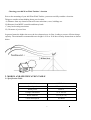
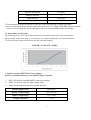
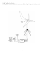
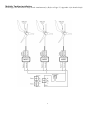
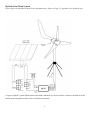
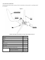
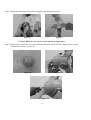
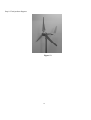
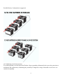
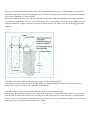
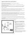
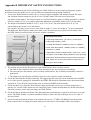
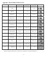
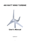
600 WATT WIND TURBINE
User’s Manual
TABLE OF CONTENT
1. SAFETY…………………………………………………………………………………………………......1
1.1 Mechanical Hazard…………………………………………………………………………………….....1
1.2 Electrical Hazard………………………………………………………………………………………....1
2. MODEL AND SPECIFICATION TABLE………………………………………………………………….3
2.1 Specification Table…………………………………………………………………………………….....3
2.2 Performance Specifications…………………………………………………………………………........4
3. DIGITAL-CONTROLLED MPPT WIND POWER CHARGER…………………………………………...4
3.1 System Wiring Diagrams………………………………………………………………………………...5
4. PACKAGE CONTENTS…………………………………………………………………………………….9
5. INSTALLATION RPOCEDURE…………………………………………………………………………..10
6. MAINTENANCE…………………………………………………………………………………………...15
7. FAQS………………………………………………………………………………………………………..15
TROUBLE SHOOTING………………………………………………………………………………………..19
WARRANTY…………………………………………………………………………………………………...19
APPENDIX A MECHANICAL STOP SWITCH………………………………………………………………22
APPENDIX B IMPORTANT SAFETY INSTRUCTIONS…………………………………………………….23
APPENDIX C BEAUFORT WIND SCALE…………………………………………………………...………24
1. SAFETY
Your 600 Watt Wind Turbine is designed with your personal safety as the first priority.
However, there are still some inherent dangers involved with any electrical and/or mechanical equipment.
Safety must be the primary concern as you plan the location, installation and operation of the turbine.
Please read the following:
Important Safety Instructions
Please take the time to read through this manual prior to assembly.
1) Place this instruction manual in a safe place for reference.
2) Wait until a calm day to install or perform maintenance on your Turbine with activation of MPPT
brake or mechanical stop switch.
3) Listen to your Turbine should you hear any mechanical noise, maintenance may be required,
please contact The Products Customer Service.
4) After installation re-adjust and tighten the screws and bolts.
5) Adhere to proper grounding techniques as established by the NEC.
6) Your Wind Turbine must be installed in accordance with this manual and local and
national building code. Incorrect installation may void your warranty.
7) Wind turbine blades spin at a potentially dangerous speed this must be respected. Never
approach a turbine in motion.
8) Note wire size (gauge chart included) prior to wiring. Any under sizing of wire can be potentially
dangerous.
1.1 Mechanical Hazard
Rotating blades present the most serious mechanical hazard. The rotor blades are made of very
strong thermoplastic. At the tip, the blades may be moving at velocities over 15m/s. At this speed, the
tip of a blade is nearly invisible and can cause serious injury. Under no circumstances should you install the
turbine where a person could come in contact with moving rotor blades.
1.2 Electrical Hazard
The 600W Turbine is equipped with sophisticated electronics designed to provide protection from electrical
dangers. Please note that the inherent personal dangers from electrical current still exist, therefore caution
should always be used when connecting this and other electrical devices.
Heat in a wiring system is often a result of too much current flowing through an undersized wire or through
a bad connection. Please consult wire guide table below.
Batteries can deliver a dangerous amount of current. If a short circuit occurs in the wiring from the batteries,
a fire can result. In order to avoid this threat, a properly sized fuse or circuit breaker is required in the lines
connecting to the battery.
2
Choosing your 600 Watt Wind Turbine’s location
Prior to the mounting of your 600 Watt Wind Turbine, you must carefully consider a location.
Things to consider when thinking about your location
A) Distance from any obstacles that will cause turbulence, trees, buildings etc.
B) Distance from MPPT controller and battery bank
C) Any local zoning restrictions
D) Clearance of power lines
In general terms the higher the tower the less obstruction to air flow, leading to a more efficient charge
capacity. The minimum recommended tower height is 30 ft or 20 ft above nearby obstructions as shown
below.
2. MODEL AND SPECIFICATION TABLE
2.1 Specification Table
Model
600W Turbine
Rated speed
12.5 m/s (41 ft/s)
Rated power
600W #
Voltage with MPPT
12 or 24V ##
Rotor diameter
1.31 m (4.2 ft)
Cut-in wind speed
4.5 MPH
3
Survival wind speed
157 MPH*
Number of blades
3
Blade material
Fiber glass
Suggested battery capacity
>100 A/Hr
* The manual brake should be turned on when the wind speed upwards 30 MPH (48 KMH).
* Survival wind speed means that the wind turbine will survive 157 MPH (250 KMH) when the manual
brake is on. Exceeding this stated wind speed will result in wind turbine failure and collapse.
2.2 Performance specifications
The following power curve shows the performance you should expect from your wind turbine.
During smooth, steady wind speed, you can expect to see output resembling the curve illustrated below.
To convert between power and current use the following formula:
POWER = VOLTAGE x AMPS
3. Digital-controlled MPPT Wind Power Charger
Please see included Manual for your MPPT Charge Controller.
MCU fully digital-controlled MPPT wind power charger.
SEPIC conversion, large DC input voltage range.
Smart load management function, braking function.
Rated Output Power
600W Max.
Battery Voltage Range
12V or 24V DC
Input Voltage Range
5~75 Vrms
Charger Efficiency
>87%
4
Battery Protection Voltage
12V - 14.4V (Lead-acid batteries) or
15.8V (Deep-cycle batteries)
24V - 28.8V (Lead-acid batteries) or
30V (Deep-cycle batteries)
Rated Load Current
35A Max.
Over-Speed Braking
<=1400 rpm
Caution: Please review the following wire gauge table to install the correct wire gauge.
We recommend these as the minimum wire sizes for optimal performance.
Always use the largest gauge wires that are practical and affordable. Local, state, and or national electrical
codes take precedence over these general recommendations.
2
12 volt System, AWG / Metric Wire Size mm
2
24 volt System, AWG / Metric Wire Size mm
Number of
Turbines:
0-30 ft.
(0-9 m)
30-60 ft.
(9-18 m)
60-90ft
(18-27 m)
90-150 ft.
(27-46 m)
150-190 ft.
(46-58 m)
190-250 ft.
(58-76 m)
250-310ft
(76-95 m)
310-390 ft.
(95-119 m)
390-500ft
(119-152 m)
1
2
3
14/2.5 mm2
12/4 mm2
10/6 mm2
8/10 mm2
6/16 mm2
4/25 mm2
4/25 mm2
000/90 mm2
000/90 mm2
12/4 mm2
8/10 mm2
6/16 mm2
4/25 mm2
4/25 mm2
2/35 mm2
2/35 mm2
1/50 mm2
0/50 mm2
2
2
2
2
2
2
2
10/16 mm
2
8/10 mm
6/16 mm
4/25 mm
2/35 mm
2/35 mm
1/50 mm
0/50 mm
00/70 mm2
System protection (see also included manual)
Your MPPT charge controller comes equipped with state of the art overcharge protection.
Temperature of the internal circuitry is moderated by an internal fan that is activated at 45°C(110°F).
When the temperature of the MPPT exceeds 65°C(150°F) your MPPT will automatically apply both the
internal fan and braking system to your Wind Turbine to prevent damage.
3.1 System wiring diagrams
There are multiple options to connect your Wind Turbine depending on your power requirements and
available components.
5
Single Turbine installation:
Please apply the Mechanical Stop Switch simultaneously. (Refer to Page 22, Appendix A for detailed info)
6
Multiple Turbine installation:
Please apply the Mechanical Stop Switch simultaneously. (Refer to Page 22, Appendix A for detailed info)
7
Hybrid Solar/Wind System
Please apply the Mechanical Stop Switch simultaneously. (Refer to Page 22, Appendix A for detailed info)
A typical “hybrid” system (Photovoltaic and Wind combined) is wired as follows, whenever feasible wire the
turbine and solar panels to their own set of battery terminals.
8
4. PACKAGE CONTENTS
Check the parts listed with the contents of the box and make sure that you have everything needed
for assembly.
Figure 1
Vertical Stabilizer
Generator
Hub
Blade
Nose Cone
Base
Caution: The edges of the blades are sharp. Please handle with care.
Name
Quantity
Turbine
1
Blade
3
MPPT Charger Controller
1
Hub
1
Vertical Tail
1
Nose Cone
1
Amp Meter
1
Brake switch (Mechanical Stop Switch)
1
Inverse tooth Nut (M14xP2.0)
1
Hex Screw (M6XL40)
9
Nut (M6)
9
9
Accessory Pack
Replacement
Accessory Pack
Hex Screw (M5XL50)
1
Washer (M14)
1
Washer (M6)
9
Hex Key no.5
1
Hex Key no.3
1
Rubber Spacer
1
Hex Screw (M5XL20)
4
Spacer for Vertical Tail
4
Inverse tooth Nut (M14xP2.0)
1
Hex Screw (M6XL40)
9
Nut (M6)
11
Hex Screw (M5XL50)
1
Washer (M14)
1
Rubber Spacer
1
Hex Screw (M5XL20)
4
Washer (M6)
11
Hex Screw (M6XL35)
2
5. INSTALLATION PROCEDURE
Step1: Open box to ensure all parts are present, remove the hub from the box.
Figure 2
10
Step 2: Take out the blades from box and fasten the blades on the hub with nuts.
Figure 3
Figure 4
Caution: Make sure that all of the bolts are secured with nuts.
Step 3: Tail Fin assembly. Use the four supplied spacers and HEX screws, to firmly connect the Tail Fin
to the hub.
Figure 5
11
Adhesive strip should be wrapped around your Tower (not included) to increase secure connection to
the Yaw shaft.
Step 4: Take out the wind turbine from box and put the cables through the mast.
Figure 6
Step 5: Attach a rubber spacer to your chosen tower (not included). To install the wind turbine to the tower
and securely fasten the bolt by using the hex wrench.
Caution 1: Ensure that rubber spacer is attached to the tower pole prior to turbine installation, otherwise
the turbine will be overtight and unable to sustain vibrations. Any product damage caused by
operations without rubber spacer is not included in the warranty as well.
Caution 2: Owing to the base of the turbine, the outside diameter of the iron pipe should be 48.3mm to
48.6mm and the wall thickness should be 1.9mm at least.
Figure 7
12
Step 6: Install the hub on the wind turbine using M14 nut and spring washer.
Figure 8
Figure 9
Caution: Make sure the nut is secured with the spring washer.
Step 7: Put the sleeve inside the nose cone and fasten the nose cone to the hub. Apply pressure to the
connections to ensure a secure fit.
Figure 10
Figure 11
Figure 12
13
Step 8: Final product diagram.
Figure 13
14
6. MAINTENANCE
Your 600 Watt Wind Turbine has been designed to run for long periods without requiring any maintenance.
Performance will be enhanced if you periodically inspect your system.
Review the following simple maintenance procedures and implement every six months.
Caution: Do not go near the wind turbine during operation.
Caution: The blades are sharp. Please handle with care.
• Check blades for superficial damage. Replace blades if damaged. It is important to not use blades
that are damaged, as you will lose overall balance, resulting in a decrease in efficiency.
Should you notice damage to the blades you must replace all 3. The blades are balanced as sets.
• Check the blade bolts and the hub nut for tightness.
• Check nosecone for cracks and tighten nuts.
• Wipe any excess dirt build-up from the blades.
• Check all electrical connections to make sure they are tight and free from corrosion.
• Check the voltage of your battery bank with a Multi-meter and clean the terminals.
• We suggest replacing the blades every five years for optimal performance.
7. FAQS
(1) How does the 600 Watt Wind Turbine control power and RPM in high winds?
Your Turbine’s operation will be halted to reduce the risk of damage due to overcharge and over spin
of the rotor blades. This process of braking is handled internally through your Turbines electronics.
(2) What is the maximum wind speed the 600 Watt Wind Turbine will survive, and do I need to take it
down in a storm?
Your wind turbine is designed to operate in most climatic conditions. Should you expect or experience
winds of 150MPH upwards, please turn off the MPPT controller which will in turn manually apply the
braking system to protect from any over spin. Once the Turbine has stopped it is possible to lay down
the Tower to offer further protection.
(3) How long will the bearings or other wearing parts last?
According to engineering calculations, the bearings should have a 10-year life span in 12- mph (6 m/s)
average wind speed sites. Bearing life will vary from one application to another; however, you should
expect at least a five-year performance in adverse conditions and 10 years in normal conditions.
(4) Can the 600 Watt Wind Turbine be connected in reverse-polarity to the battery without causing any
damage?
15
Reverse polarity will cause damage to both your MPPT controller and battery if not quickly remedied.
Always double check any wiring to reduce the risk of reverse polarity. Your turbine is equipped with polarity
protection to reduce the risk of damage, but it is still possible to degrade your wiring and cause damage to the
overall system.
(5) Will it hurt my 600 Watt Wind Turbine to short-circuit the output?
No, the 600 Watt Wind Turbine is designed to be short-circuited as a normal shutdown procedure by a fuse.
The function of the stop switch is to both disconnect the turbine from the batteries as well as short-circuit the
output of the turbine.
(6) Where can I locate tubing to make a tower?
Your 600 Watt Wind Turbine is designed to make mounting as simple and straightforward as possible.
Should you not wish to purchase the custom tower kit feel free to utilize schedule 40 1.5 inch steel tubing.
This should be available through your local hardware outlet.
(7) What is the difference between copper and aluminum wire?
Generally aluminum wire is less conductive, so it must be bigger for the same amp load and resistive losses as copper.
The 600 Watt Wind Turbine uses copper or tinned copper for the yaw wires.
(8) What battery should I choose for my 600 Watt Wind Turbine?
There are multiple battery options in today’s market– flooded lead acid, absorbed Glass mat (AGM), gel cell
and NiCad. There is no definitive choice for your alternative energy needs. Normally the choice of battery is
determined by availability and pricing. Should you have questions regarding batteries please consult a local
battery supplier. Or view: www.batterycouncil.org. The capacity of your battery bank is determined by your
use. Below is a good guideline.
• 12-volt systems – 400 Amp-hours
• 24-volt systems – 200 Amp-hours
16
Possible Battery Configurations (suggested)
(9) Is lightning protection necessary?
You should ground your 600 Watt Wind Turbine. Proper grounding (illustrated below) provides protection to
individuals and equipment by eliminating the possibility of dangerous voltage. Remember a steel tower is a
conduit for lightning.
17
Every wind turbine and turbine tower needs to be grounded at the tower base even though the system may be
grounded at the battery bank. Grounding the tower at its base may help prevent shocks to persons touching the
tower due to lightning or electrical faults.
Please take the time to review the National Electrical Code (NEC) and local building and zoning regulations
for complete requirements. Even in “Off Grid Systems” there are multiple ways for tower grounding, the most
common method is a copper clad steel electrode(s) driven into the soil. Please view the following grounding
diagram.
(10) What effect does radio interference have on my 600 Watt Wind Turbine?
The internal circuitry of the 600 Watt Wind Turbine is shielded and filtered to prevent radio interference,
and has been tested to insure electro-magnetic compatibility.
(11) What effect does my 600 Watt Wind Turbine have on radio transmissions?
The 600 Watt Wind Turbine normally does not affect radio transmitters. Care should be taken, however, to route power
lines from the 600 Watt Wind Turbine away from the power and antenna lines of a radio transmitter. An old ham radio
operator’s trick is to twist positive and negative wires together to provide an even distribution of EMF noise across both
wires, which serves to cancel out the electrical noise created.
18
This technique can be used on the 600 Watt Wind Turbine power lines, on the radio’s power lines, and on
transmission wires. Transmission lines should always be kept as far from power lines as is practically possible.
Proper grounding of the Turbine and other system components must also be observed.
(12) Will it affect the regulation of my 600 Watt Wind Turbine to install an RF (radio frequency) filter?
An RF filter should not affect the regulation of the Turbine, but any electronic devices placed in line with the turbine
must be rated for the proper current and voltage. It is best to place any line filters on the power lines for the load
device that requires it, and as close to the device as possible.
Trouble shooting
You may require an extra person to assist with these tests.
1) Remove the blade/hub from the turbine. Replace the rotor hub nut on the rotor shaft.
2) Quickly spin the rotor shaft manually with your fingers while connecting and disconnecting the red and
black wires (turbine must not be connected to batteries).
3) With the red and black wires connected to each other, the shaft should be more difficult to turn.
When the wires are disconnected it should spin freely.
Should this not be true please contact supplier or manufacturer.
4) With your 600 Watt Wind Turbine connected to your battery bank, use an electric hand drill to spin the
rotor shaft.
5) Below 500 RPM, the rotor should spin freely without friction.
6) At 500 RPM and above, the Wind Turbine should be charging the battery. You should feel resistance on
the rotor shaft if the shaft is not rotating; contact your turbine dealer or manufacturer.
Be aware your battery banks needs to be under 12V or 24V for this testing as the Turbine needs to read
a charge.
Warranty
We warrant your product to be free from defects in material and/or workmanship for a period of 1 year from
original date of purchase. Warranty coverage is extended only to customer (original purchaser).
If product proves defective during warranty period, manufacturer, at its option will:
1. Replace wind turbine with new or refurbished product.
2. Correct reported problem
Customers warranty continues to be valid on repaired or replaced product from original warranty date.
Restrictions
This warranty covers defects in manufacturing discovered while using the product as recommended by the
manufacturer. The warranty does not apply to a) equipment, materials, or supplies not manufactured by
19
manufacturer. b) Product that has been modified or altered other than by manufacturer or without prior
manufacturer’s approval. c) Has been exposed to winds exceeding 157mph. d) Windstorms (upwards of
Beaufort Wind Scale 7), lightning and Hail damage. e) Repairs performed by other than authorized support
staff. f) All acts of God; misuse, negligence or accidents. g) Tower foundation and wire has not been installed,
operated, repaired or maintained in accordance with the instructions supplied by manufacturer. Any service
identified in the above list or product is found not to have any defect in manufacturers’ workmanship or
materials the customer will be responsible for the costs of all repairs and expenses incurred by manufacturer.
Disclaimer
EXCEPT FOR THE EXPRESSED WARRANTY SET FORTH ABOVE, THE MANUFACTURER
DISCLAIMS ALL OTHER EXPRESSED AND IMPLIED WARRANTIES, INCLUDING THE
IMPLIED WARRANTIES OR FITNESS FOR A PARTICULAR PURPOSE, MERCHANTABILITY
AND NON-INFRINGEMENT. NO OTHER WARRANTY, EXPRESSED OR IMPLIED, WHETHER
OR NOT SIMILAR IN NATURE TO ANY OTHER WARRANTY PROVIDED HEREIN, SHALL
EXIST WITH RESPECT TO THE PRODUCT SOLD UNDER THE PROVISIONS OF THESE
TERMS AND CONDITIONS. THE MANUFACTURER EXPRESSLY DISCLAIMS ALL LIABILITY
FOR BODILY INJURIES OR DEATH THAT MAY OCCUR, DIRECTLY OR INDIRECTLY, BY USE
OF THE PRODUCT BY ANY PERSON. ALL OTHER WARRANTIES ARE EXPRESSLY WAIVED
BY THE CUSTOMER.
Warranty Claims & Return Policies
To be eligible for service under this warranty, customer must either contact manufacturer either through
written request or by telephone to submit a service request for the wind turbine covered by this warranty
within specified period (1 year from original date of purchase) and request a return authorization (RA)
number, This RA # must be issued before any product can be returned.
All notifications must include the following information:
a) Description of alleged defect
b) How the wind turbine was being used
c) Serial #
d) The original purchase date
e) Name, phone #, address of party requesting warranty
Within 2 to 3 business days we will provide the customer with an RA# and will direct customer
to location where the product is to be returned. Once an RA has been issued the customer has 30 days to return
the product. Failure to deliver the product within the 30 days results in the RA as no longer being valid and a
new RA must be issued. Manufacturer is under no obligation to accept any product that is returned to them
without a proper RA #.
20
Limitation of Liability
UNDER NO CIRCUMSTANCES WILL THE MANUFACTURER OR ITS AFFILIATES OR
SUPPLIERS BE LIABLE OR RESPONSIBLE FOR ANY LOSS OF USE, INTERRUPTION OF
BUSINESS, LOST PROFITS, LOST DATA, OR INDIRECT, SPECIAL, INCIDENTAL, OR
CONSEQUENTIAL DAMAGES OF ANY KIND REGARDLESS OF THE FORM OF ACTION,
WHETHER IN CONTRACT, TORT (INCLUDING NEGLIGENCE), STRICT LIABILITY OR
OTHERWISE, RESULTING FROM THE DEFECT, REPAIR, REPLACEMENT, SHIPMENT OR
OTHERWISE, EVEN IF THE MANUFACTURER
OR ITS AFFILIATE OR SUPPLIER HAS BEEN ADVISED OF THE POSSIBILITY OF SUCH
DAMAGE.
Neither the manufacturer nor its affiliates or suppliers will be held liable or responsible for any damage or
loss to any items or products connected to, powered by or otherwise attached to the hardware.
The total cumulative liability to Customer, from all causes of action and all theories of liability, will be limited
to and will not exceed the purchase price of the Product paid by Customer. This warranty gives the Customer
specific legal rights and the Customer may also have other legal rights that vary from state to state or province
to province.
21
Appendix A MECHANICAL STOP SWITCH
The MPPT controller has an integrated battery controlled braking mechanism.
This is explained in your MPPT manual.
Further to this protection we have incorporated a secondary level of safety and convenience with
a mechanical 3-phase AC brake.
During periods of high winds (upwards of 30 mph, 13m/s) it is strongly advised to utilize your MPPT
brake and your mechanical stop switch. The use of your mechanical stop switch will not affect the
voltage of your battery.
We strongly advises the activation of the mechanical stop switch during any maintenance of or around
your 600 watt turbine. This will prevent the blades spinning and voltage to be transferred.
Likewise during initial installation please activate the mechanical brake. The final step in installation
of turbine, controller, and battery should be release of this mechanical stop switch.
The mechanical stop switch is pre-wired for your convenience with 10 AWG wire and battery terminal
connections. The wire configuration is explained in the diagram below (fig 1).
Place the corresponding wires (red,black,blue) from the mechanical stop switch into the MPPT input
terminals. This should match the similar colored wires from your turbine. Your turbine and stop switch
share input terminals on the MPPT. This provides a parallel connection.
Test the connection of your mechanical stop switch at the point of initial installation. Push the brake
“ON”. You should see the turbine stop its rotation. Continue to apply this brake during the remainder
of your installation.
Should the turbine continue to spin, check your terminal connections. Do not approach the turbine without
activation of this mechanical stop switch under any circumstance!
Notes
• It is not necessary to apply MPPT brake
during activation of the mechanical stop
switch.
• It is strongly advised to test both mechanical
and MPPT stop switch periodically.
• Your mechanical stop switch is pre-wired with
10 AWG wire, this should not be altered.
• The mechanical stop switch should be placed
close to your MPPT in a dry ventilated
environment.
• For multiple turbine applications please use
one mechanical stop switch for each wind
turbine.
• This mechanical stop switch has been designed
specifically for your Wind Turbine; it should not
be incorporated into other models.
22
Appendix B IMPORTANT SAFETY INSTRUCTIONS
Read these instructions below before installing your Wind Turbine to ensure people and property against
accidents. Please also make sure it is set up under environmental and operating conditions.
1. Locate your Wind Turbine in windy sites so as not to disturb neighbors and animals around. The noise
and vibration element cannot be got rid of even if Wind Turbine offers the lowest noise than
any others on the market. The better location of your Wind Turbine requires avoiding personnel or animal
activities within a 33 ft (10 m) radius, and human habitation and wildlife within a 66 ft (20 m) radius.
2. The height of installation should be 22 ft (7 m) to 33 ft (10 m). The wind speed below 22 ft (7 m)
constrained by the terrain is low and chaotic.
For example: If winds in your area are more than 30 mph (13.4 m/s), the height of 7 m is recommended.
The higher the Wind Turbine stands (more than 10 m), the much stress your pole kit will sustain. Also,
the Wind Turbine possibly brakes in extreme weather conditions.
Operating Environment:
A. Operating Temperature: -4°F (-20°C) ~ 122°F (50°C)
B. Operating Humidity: < 80%
C. Average Wind Speed: < 30MPH (<13 m/s or <48KMH)
D. Max. Peak Wind Speed: < 45MPH (<20m/s or <70KMH)
E. Elevation: < 1000m
F. Applicable Installation Height: 8.85ft〜33ft (2.7m〜10m)
It is subject to IEC 61400-2 safety standards. If the operating
temperature and wind speed exceed the above-mentioned
limits, please turn on the manual brake in proper way to
shut off the Wind Turbine.
3. The rooftop may not be the best place for your Wind Turbine. Here are three reasons.
a. The flow is more turbulent above the rooftop and leads to the low wind power availability.
b. The stress the pole kit sustains varies in rooftop constructions. The evaluation and stability cannot be
guaranteed.
c. The slight noise and vibration still affect sleep for some sensitive people and animals.
4. Check the manual brake health periodically. We suggest that the users turn on the manual brake of MPPT
to see if the speed is getting low. Meanwhile, the RED LED should be illuminated once the manual brake
is turned on. If you hear the sound of the relay, it means the MPPT works normally.
5. Check the three wires from the Wind Turbine output periodically. Please use a current clamp meter to
measure AC current. If the outputs are not consistent, please contact the distributor for further instruction.
For safety reasons, please stop operating your Wind Turbine.
6. Check the battery health periodically. The abnormal battery and improper connection will cause over-spin
issues. The Wind Turbine’s operation should be halted to reduce the risk of damage due to over spin of
the rotor blades.
7. Survival wind speed means that the wind turbine will survive 157 MPH (250 KMH) when the manual
brake is turned on. Exceeding this stated wind speed will result in wind turbine failure and collapse.
23
Appendix C BEAUFORT WIND SCALE
Beaufort No.
Description Calm
Avg. Wind
Speed (knot/h)
Avg. Wind
Speed (km/h)
Avg. Wind
Speed (m/h)
0
Calm
<1
<2
< 0.55
1
Light air
1-3
2-6
0.55~1.66
2
Light breeze
4-6
7 - 12
1.95~3.33
3
Gentle breeze
7 - 10
13 - 19
3.61~5.27
4
Moderate breeze
11 - 16
20 - 30
5.55~8.33
5
Fresh breeze
17 - 21
31 - 40
8.61~11.11
6
Strong breeze
22 - 27
41 - 51
11.38~14.16
7
Moderate gale
28 - 33
52 – 62
14.45~17.22
8
Fresh gale
34 - 40
63 – 75
17.5~20.83
9
Strong gale
41 - 47
76 – 87
21.11~24.16
10
Storm
48 - 55
88 – 103
24.44~28.61
11
Violent storm
56 - 63
104 – 117
28.88~32.5
12
Hurricane
≥ 64
≥ 118
Image
> 32.77
* It is strongly advised to manually turn on your Mechanical Stop Switch during periods of high winds
(upwards of Beaufort Wind Scale 7). Please refer to Appendix A for detailed information.
24