1
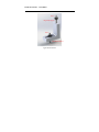
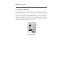
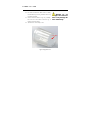
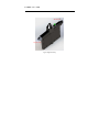
USER MANUAL D30 Accessories CORALTEC INC. User Guide CORALTEC INC. 130 Konrad Crescent • Suite 11 Markham, ON L3R 0G5, Canada Phone 1.844.604.6234 • Email [email protected] • Web: www.spraysizer.com Manual Release Date: February 2015 Manual Version: V1.0 H O R I Z O N T A L H O L D E R Contents 1 Horizontal Holder ........................................................................................................... 4 2 Vertical Holder ................................................................................................................. 6 3 Alignment Tool ................................................................................................................ 7 4 TERMS OF USE, WARRANTY & LIABILITY WAIVER.................................. 11 H O R I Z O N T A L H O L D E R 1 Horizontal Holder Horizontal holder is designed to conveniently hold the device under the spray. In order to use the horizontal holder, you have to make a hole with ¼-20 hole thread in a flat horizontal surface and attach the holder to it. It is recommended to use the extrusion aluminum bars to be able to move the stand in the horizontal direction as well. Figure 1 shows the image of the horizontal stand. There are two screws in the image. Screw 1 and its nut are used to mount the stand on the aluminum extrusion bar or the flat horizontal surface. Screw 2 is inserted at the bottom of the D30 device, where there is a female ¼-20 threaded hole. The nut on screw 1 is used to secure D30 at a desirable height. In order to install D30, first insert screw 2 inside D30, tighten the nut against the body of D30 to secure it in position and then use Screw 1 to mount the stand on the horizontal surface. . H O R I Z O N T A L H O L D E R Screw 2 Height Adjusting Nut Screw 1 Flat Horizontal Surface Figure 1 Horizontal Stand T E R M S O F U S E 2 Vertical Holder Vertical holder is designed to conveniently hold the device under the spray. In order to use the vertical holder, you have to make a hole with ¼-20 hole thread in a flat vertical surface and attach the holder to it. It is recommended to use the extrusion aluminum bars to be able to move the stand in the horizontal direction as well. Figure 2 shows the schematic of the vertical stand. One thumb screw and one regular screw are included in the stand set. The thumb screw is inserted at the bottom of D30 and its nut is used to secure it in the desired height. The second screw and its nut is used to mount the stand on the vertical surface or the aluminum extrusion bar. Thumb Screw Height Adjusting Nut Screw Figure 2 Vertical Stand T E R M S O F U S E 3 Alignment Tool The device is designed to be durable and robust in order to require minimum amount of maintenance. However, from time to time, the laser system might require alignment as change in environmental temperature, external impact, etc. can affect its alignment. A special tool is required to complete the alignment procedure. It includes a transparent alignment tool part, which resembles the end caps of D30 plus a small wrench that is used to turn the set screw on the laser side to move the laser beam in the channel to ensure that it is centered with respect to the channel at all times. Figure 3 shows the alignment tool part. It is made of transparent plastic so you can see where the laser beam is hitting. There is a mark at the center that you need to make sure that the entire laser beam is inside the mark. Figure 4 shows the proper setting to use the alignment tool. In order to check/adjust the laser alignment, perform the following procedure: 1. 2. 3. 4. Turn off the device. Secure the device on a horizontal surface. Unscrew the cap on the detector side. The detector side is the side where the power button is located. Take the detector out of the channel very carefully. Do not pull the detector from its wires as it may cause detector disconnection. Try to take the Note: The laser alignment is a very sensitive procedure and it has to perform with patience and very carefully. T E R M S 5. 6. O F U S E detector out by pulling its main body using a long-nose plier. Once the detector is out, mount the alignment tool onto the device. Turn on the laser. Now the laser beam should be visible on the alignment tool. The laser beam cross section, which is an ellipse, must be horizontal and at the center of the alignment tool. If it is not aligned properly, you need to re-align the Warning: Do not let laser the beam directly enter 7. If the laser requires re-alignment, unscrew your eyeball. Always look the cap on the laser side. 8. Using the small wrench and the three set at the reflection or screws on the laser, try to re-align the laser refraction of the laser beam. The laser beam should be positioned beam to avoid eye carefully on the center of the alignment tool damage. inside the marked area. 9. Once the alignment is complete, put back the laser cap and gradually screw it until it is firmly tight. 10. Check the alignment again to make sure closing the cap has not affected the alignment. 11. Turn off the device and take out the alignment tool. T E R M S O F U S E 12. Put back the detector. Make sure it is firmly inside and that you have pushed it all the way inside the channel. 13. Screw back the detector cap very carefully. Do not move the device until the cap is firmly screwed in place. 14. The device is now ready to use. Warning: Do not overtight the setscrews since it may damage the laser module body. Center Mark Figure 3 Alignment Tool T E R M S O F U S E Allen Wrench Alignment Cap Figure 4 Alignment Setup T E R M S 4 O F U S E TERMS OF USE, WARRANTY & LIABILITY WAIVER Coraltec Inc. (the “Company”) offers its products named as “Accessories” (the “product”) with the terms, conditions and notices as follows: 4.1 Terms of use By purchasing and accepting the delivery of the product customer agrees to be bound by and accepts the following terms, conditions, warranty, and disclaimer. 4.2 Exclusive Obligation This product may not be used for unlawful purposes and that use is expressly prohibited under the terms and conditions of the product. 4.3 Warranty No warranty is offered on this product. However the company will do its best to resolve any unlikely problem with the system. T E R M S O F U S E 4.4 Guarantees No guarantees are given or implied to the product efficiency, product performance and production or its improvement. 4.5 Limitation of Liability To the maximum extent permitted by applicable law, in no event shall the Company, its suppliers, directors, shareholders and/or employees be liable for any damage whatsoever (including without limitation, special, incidental, consequential, or indirect damages for personal injury, loss of business profits, business interruptions, loss of business information, or any other pecuniary loss) arising out of the use of or inability to use this product, even if the Company has been advised of the possibility of such damages. In any case the Company’s, its suppliers’, directors’, shareholders’ and/or employees’ entire liability under any provision of this agreement shall be limited to the amount actually paid by you for the product. 4.6 Other Statements Coraltec Inc. employees or representatives, oral or other written statements, do not constitute warranties, shall not be relied upon by buyer, and is not part of the contract for sale or this limited warranty. T E R M S O F U S E To the maximum extent permitted by applicable law, the Company and its suppliers disclaim all other warranties, either express or implied, including but not limited to implied warranties of merchantability and fitness for a particular purpose, with regard to the product and any related or accompanying written materials 4.7 General This disclaimer statement is governed by the laws of Canada. You hereby consent to the exclusive jurisdiction and venue of the Courts of Canada, in all disputes arising out of or relating to the use of this product. Use of this product is unauthorized in any jurisdiction that does not give effect to all provisions of these terms and conditions, including without limitation this paragraph. 4.8 Modification of Terms and Conditions Coraltec Inc. reserves the right to change the terms, conditions, and notices under which their products are offered. 4.9 Entire Agreement The TERM OF USE, WARRANTY AND DISCLAIMER document states the entire obligation of Coraltec Inc. with respect to the products. If any part of this disclaimer is determined to be invalid, void, unenforceable or illegal, T E R M S O F U S E including, but not limited to the warranty disclaimers and liability disclaimers and liability limitations set forth above, then the invalid or unenforceable provision will be deemed superseded by a valid, enforceable provision that most closely matches the intent of the original provision and the remainder of the agreement shall remain in full force and effects.