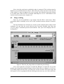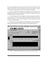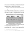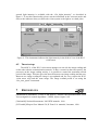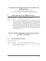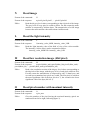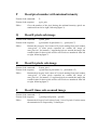
1
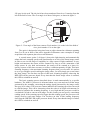
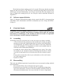
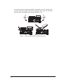
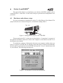
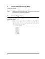
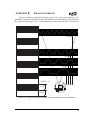
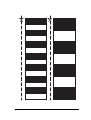
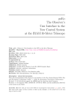
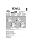
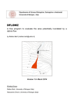
Khepera
¨
K213 VISION TURRET USER MANUAL
Version 1.2
K-Team S.A.
Lausanne, 16 March 1999
Documentation author
K-Team
Ch. de Vuasset, CP111
1028 Préverenges
Switzerland
[email protected]
http://www.k-team.com
Trademark Acknowledgements
IBM PC: International Business Machines Corp.
Macintosh: Apple Corp.
SUN Sparc-Station: SUN Microsystems Corp.
LabVIEW: National Instruments Corp.
Khepera: K-Team
NOTICE:
• The contents of this manual are subject to change without notice.
• All efforts have been made to ensure the accuracy of the content of this manual. However, should any error be detected. please inform K-Team.
• The above notwithstanding, K-Team can assume no responsibility for any error in this
manual.
TABLE OF CONTENT
Introduction . . . . . . . . . . . . . . . . . . . . . . . . . . . . . . . . . . . . . . . . . 1
How to Use this Manual . . . . . . . . . . . . . . . . . . . . . . . . . . . 1
Safety Precautions . . . . . . . . . . . . . . . . . . . . . . . . . . . . . . . . . . . . 1
Unpacking and Inspection . . . . . . . . . . . . . . . . . . . . . . . . . . . . . . 2
The vision TSL213 turret . . . . . . . . . . . . . . . . . . . . . . . . . . . . . . . 2
Overview. . . . . . . . . . . . . . . . . . . . . . . . . . . . . . . . . . . . . . . 2
Image perception. . . . . . . . . . . . . . . . . . . . . . . . . . . . . . . . . 2
Software support diskettes . . . . . . . . . . . . . . . . . . . . . . . . . 3
Connections . . . . . . . . . . . . . . . . . . . . . . . . . . . . . . . . . . . . . . . . . 3
Assembling . . . . . . . . . . . . . . . . . . . . . . . . . . . . . . . . . . . . . 4
Disassembling. . . . . . . . . . . . . . . . . . . . . . . . . . . . . . . . . . . 4
Using LabVIEW® . . . . . . . . . . . . . . . . . . . . . . . . . . . . . . . . . . . . 5
Hardware and software setup . . . . . . . . . . . . . . . . . . . . . . . 5
Image reading . . . . . . . . . . . . . . . . . . . . . . . . . . . . . . . . . . . 6
Image characteristics reading . . . . . . . . . . . . . . . . . . . . . . . 8
Other characteristics of the environment . . . . . . . . . . . . . . 8
Turret set-up . . . . . . . . . . . . . . . . . . . . . . . . . . . . . . . . . . . . 9
References . . . . . . . . . . . . . . . . . . . . . . . . . . . . . . . . . . . . . . . . . . 9
Appendix A: Communication protocol to control the K213
vision turret . . . . . . . . . . . . . . . . . . . . . . . . . . . . . . . . . . . 10
Appendix B: Image examples . . . . . . . . . . . . . . . . . . . . . . . . . . 15
1
INTRODUCTION
The hardware of Khepera is based on a modular concept. The “K213 vision turret”
can be plugged on the top of the Khepera robot to extend its functionalities to linear grey
level vision. Due to the configuration and the geometric shape of this turret, no other turret can be plugged on the top of this one. This kind of turret is called a “top turret”.
The K213 vision turret is controlled by a local Motorola 68HC11 processor. A
local network makes the communication with the main processor possible. All functionnalities can be managed by a local protocol supported by the standard control protocol
available on the basic configuration of Khepera. This turret can be used only on a
Khepera robot with a BIOS and protocol version greater or equal to 4.0.
1.1
How to Use this Manual
This manual is organised into six chapters and an appendix. To learn how to make
the best use of your K213 vision turret you are urged to read all of chapters 2 through 5.
You need to read the chapter 6 if you use the software LabVIEW®. The appendix can be
referred to as necessary.
Chapter 1
gives you a general introduction.
Chapter 2
describes some important warnings.
Chapter 3
explains the contents of the package.
Chapter 4
explains the functionality of the K213 vision turret.
Chapter 5
explains how to connect the K213 vision turret to the robot
and to the host computer.
Chapter 6
is addressed to users of LabVIEW®. It shows some virtual
instruments to control the K213 vision turret functionality.
Appendix A details the commands of the communication protocol.
Appendix B illustrates some examples of image acquisition.
2
SAFETY PRECAUTIONS
Don't plug or unplug any connector or turret when the robot is powered (by batteries or external power supply). All connections and turret insertions must be made when
the robot and the interface are switched OFF. Otherwise damages can occur.
Switch OFF the robot if you will not use it for more than a day. Please disconnect the
power supply removing it from the wall socket.
If you have any question or problem concerning this turret, please contact your Khepera
dealer.
1
3
UNPACKING AND INSPECTION
Please check that you have a complete package. You should find:
• Documentation.
• The K213 vision turret.
• Disks with the software modules for LabVIEW® on SUN®, Macintosh®
and PC. Please note that LabVIEW® itself is NOT included in the package.
4
THE K213 VISION TURRET
4.1
Overview
Top view
Side view
5
3
2
4
1
Figure 1: Overview of the turret layout.
Make an external inspection of the turret. Note the location of the following parts:
1. Serial line (S) connector.
2. Image perception optics.
3. Light intensity detector optics.
4. 68HC11 general purpose processor board.
5. Vision specific piggy-back.
4.2
Image perception
On the upper board there are two sensors, situated behind the two optics (2 and 3 as
described in figure 1): The linear image sensor and a global light intensity detector.
The image sensor is an array of 64x1 cells, giving a linear image of 64 pixels with
2
256 grey-levels each. The 64 pixels have been numbered from 0 to 63 starting from the
left of the field of view. The view-angle is of about 36 degrees, as shown in figure 2.
Pixe
l 63
36°
l0
Pixe
Figure 2: View angle of the linear camera. Pixel number 0 is on the left of the field of
view, pixel number 63 is on the right.
The optics is designed to bring into focus an object situated at a distance spanning
from 5 to 50 cm in front of the robot. Appendix B illustrates some examples of image
acquisition with a pattern placed at several distances.
A second sensor (point 3 of figure 1) detect the light intensity and automatically
adapts the basic scanning speed (same functionality as an iris) of the linear image sensor
in order to use its full range of sensibility in a large extent of light conditions. In very
bright environments, the sensor will be scanned very fast, to avoid a saturation of the
image sensor. In very dark environments, the sensor will be scanned at a lower frequency, because of the time necessary to collect a sufficient quantity of light. This basic
scanning frequency is the maximum scanning frequency that you can reach. It is useless
to try to get a higher speed in asking the image often, you will simply get several times
the same image. You can have an idea of this basic scanning frequency observing the
RED LED on the processor board. Every time that the linear image sensor is scanned,
this LED is switched on and off.
The basic scanning process described above is made automatically by a specific
hardware. The 68HC11 processor is informed about every scan and can read the image
generated by the scanning, converting the analog signal generated by the image sensor
into grey level values. The processor cannot influence the scanning speed, but can avoid
to read the image. This can be interesting when the robot is in bright environments. In
this kind of situation the scanning frequency is very high and the processor would be
overloaded if it had to convert each image. For this reason you can specify a maximum
reading speed. If the scanning speed is bigger that this reading speed, the processor will
simply avoid to read some images. You can have an idea of this reading frequency
observing the GREEN LED on the processor board. Every time that the image is readed,
this LED is switched on and off.
3
The default maximum reading speed is 0,2 seconds. This means that the maximum
image rate that you can get is 5 Hz. The fact to ask often the image data to the processor
will not give you more information: you will get several times the same image. If you
want to change this reading speed you can, using the control command described in
Appendix A.
4.3
Software support diskettes
Three 3,5˝ diskettes contain all the modules for the control of the K213 vision turret from
LabVIEW® on PC, Macintosh® and SUN® workstations (see also “Using LabVIEW®”
on page 6).
5
CONNECTIONS
Assembling and disassembling additional turrets is a delicate operation. Try to
avoid it as much as possible and perform it carefully. Please follow the following
instructions to avoid damage to your modules. K-Team can assume no responsibility for any damage caused by improper manipulation.
5.1
Assembling
Assembling is the easier operation, but it is also necessary to perform it carefully:
• First of all choose the parameters of the module on to which you plan to
plug the new turret (the running mode that you will use on the basic Khepera configuration, for instance) and set the jumpers if necessary. When the
turrets are assembled, it is impossible to access to the modules that are
inside the robot without disassembling it.
• Assemble the turret with the basic configuration in two steps: First, place
the module on the extension connector checking that all pins are seated
correctly. Second, apply force to insert the turret into the extension connector.
• If you want to connect the robot to your workstation, use the serial connector of the topmost turret.
• Operate as normal.
5.2
Disassembling
This is the most difficult operation for people that are not accustomed working with this
type of hardware.
• First switch OFF the robot or disconnect the power supply.
• Separate the turret from the rest of the robot. To perform this without damage to the connections, it must be removed carefully such that all pins are
disconnected simultaneously. One way to do this is to insert a large plastic
4
screwdriver between adjacent modules and gently ease the boards apart,
being careful not to push on delicate components. First open one side a bit,
then the other, alternating sides until the module is free.
Figure 3: How to disassemble an additional turret.
5
6
USING LABVIEW®
The goal of this chapter is to familiarise you with the LabVIEW modules used to
control the K213 vision turret. To this end, all steps to perform turret manipulations are
presented.
6.1
Hardware and software setup
MC68331
Set your environment as explained in section 5.2 of the Khepera User Manual. The
jumpers must be set as showed in figure 4, to obtain the running mode 2.
Top view
Figure 4: Settings of the jumpers to use LabVIEW.
Then assemble the K213 vision turret as described in “Connections” on page 4 of
this manual and finally connect the robot to the computer as described in section 5.2 of
the Khepera user manual.
To enable the exchange of information between your computer and the robot, you
have to set up the serial link. Be sure that the connection cable is connected at both ends,
that the robot is powered, then start LabVIEW and open the “Set-up” instrument present
in your diskette. The following panel appears:
Figure 5: Set up panel for serial link initialisation.
6
Now, select the serial port on which the robot is connected. This selection must be
made for every module that you will use. Then click once on the run arrow at the top left
of the window. A stop icon appears for a few seconds, after what the front panel returns
to its initial state. That's all! The serial link with Khepera is set to 19200 baud. It will
remain so until you put your computer off.
6.2
Image reading
There are several possibilities to get images from the K213 vision turret. These
possibilities differ essentially at the level of the resolution and the format of informations.
The first instrument we will look at is used to get the complete linear image at full
resolution. Be sure that the serial link has been correctly installed, then open the
“Get_lin_image” instrument present on the diskette. Now your screen displays the following panel:
Figure 6: The Get_lin_image allow to read the 64 pixels image.
Now, select again the serial port on which the Khepera is connected. To test this
module, put a large and contrasted image in front of the robot, at a distance of 10-20 cm.
To read the image from the robot, just click once on the run arrow. Move the image and
click again. If you are getting bored with clicking on the arrow, try one click on the dou-
7
ble arrow (in running mode). By this way, you enter the recurrent running. Move the
image in front of the vision system and observe the result on the panel in real time.
Switch ON and OFF the autoscale function (top right of the “visual_cluster” scope) to
observe the effect on the display. Click on the stop icon to halt the program.
The “Get_lin_image_4bit” instrument is very similar to the “Get_lin_image”. The
only difference is that in “Get_lin_image_4bit” the bit/pixel resolution is reduced to 4
bits/pixels instead of the 8 bit/pixels used by “Get_lin_image”. This make a faster image
acquisition possible, still having all 64 pixels.
“Get_2x_subscan” and “Get_4x_subscan” are also two instruments very similar to
the previous two. Also in this case the resolution of the image is reduced in order to get a
faster transmission. In “Get_2x_subscan” the pixel resolution of the image is reduced,
and only one pixel out of two is sent and displayed. In “Get_4x_subscan” only a pixel
out of four is sent and displayed.
The instrument “Get_8pix_subimage”, presented in figure 7, uses the possibility to
ask for 8 successive pixels (sub-image) of the linear image starting from “start_pixel”. A
slider in the upper right corner is used to define the start point of the sub-image.
Figure 7: Instrument for the acquisition of 8 successive pixels in the image.
8
Also in this case, to test the instrument, please select the serial port on which the
Khepera is connected. To test this module, put a large and contrasted image in front of
the robot, at a distance of 10 cm. To read the image from the robot, click on the double
arrow to enter the recurrent running. Move the “start_pixel” slider and observe the result
on the panel in real time. Click on the stop icon to stop the program.
The instrument “Get_16pix_subimage” has the same functionality as the instrument “Get_8pix_subimage” but ask for 16 successive pixels instead of 8.
6.3
Image characteristics reading
In addition to some simple format changes and pixel extraction, the local 68HC11
processor of the K213 vision module is programmed to make some very simple preprocessing of the linear image. Two very simple instruments are presented here to get the
number of the pixel with maximal (figure 8) and minimal intensity. The analysis of the
image is made at the level of the K213 vision turret and only the final result is transmitted to this instrument through the Khepera main processor.
Figure 8: This instrument access to a preprocessing operation made by the local processor: the computation of the pixel with maximal intensity.
To test the “Get_pixel_max” instrument please run it in the recurrent mode (double
arrow in running mode) and move a lamp in front of the robot. The maximum pixel will
move with the lamp and indicates the direction of the light source.
The “Get_pixel_min” instrument is very similar but gives the number of the pixel
having the minimum intensity. The same test as above can be made replacing the light
source with a black line on a white surface.
6.4
Other characteristics of the environment
As described in section “Overview” on page 2, the turret is provided with a light
intensity detector, used to adjust the image sensor sensibility. This information about the
9
general light intensity is available with the “Get_rlight_intensity”, as described in
figure 9. To test this functionality please run the instrument in the recurrent mode and
observe the indicator when you direct the vision system to the light or to a dark place.
Figure 9: This instrument indicates the light intensity in the field of view of the K213
vision turret.
6.5
Turret set-up
The 68HC11 of the K213 vision turret manages on one side the image reading and
on the other side the communication network. To have a control on the time spent by the
processor on the image reading activity, it is possible to control the maximum refresh
period of the image. This time gives the interval between one image reading and the next.
Between two image reading the image is not updated and for every request the K213
vision turret will send the same image. The image readind period is set using the
“Set_scan_speed” instrument.
7
REFERENCES
[Mondada93b] Mondada F., Franzi E. and Ienne P., "Mobile robot miniaturisation: a tool
for investigation in control algorithms.", ISER3, Kyoto, Japan, 1993.
[National98] National Instruments, LabVIEW manuals, 1998.
[K-Team98] Khepera User Manual 5.0, K-Team S.A. manuals, Lausanne, 1998.
10
APPENDIX A
COMMUNICATION PROTOCOL
TO CONTROL THE
K213 VISION TURRET
This communication protocol allows complete control of the functionnalities of the
K213 vision turret through a RS232 serial line and the robot main processor. The connection configuration needed is presented in section 5.2 of the Khepera USER MANUAL.
The setup of the serial line of your host computer must correspond to the one set on the
robot with the jumpers (running modes 1 to 3).
The protocol used to control the K213 vision turret from the robot should not be
confused with the protocol used to control the robot from a host computer. We call the
robot control protocol “main protocol” and the K213 vision turret control protocol “turret protocol”.
The “T” command of the main protocol transmits a command of the turret protocol
to the additional turret with the given identification number (see appendix A of the Khepera USER MANUAL). The identification number of the K213 vision turret is 2.
The turret protocol is constituted by commands and responses, with an header in
ASCII codes, like for the main protocol. The string of the turret protocol must be inserted
in the command field of the T order of the main protocol (see appendix A of the Khepera
USER MANUAL). A command of the turret protocol is constituted by a capital letter
followed, if necessary, by 8 bit (0 to 255) numerical parameters separated by a comma.
The response is transmitted in the response field of the command T of the main protocol.
The response is constituted by the same letter of the command but in lower case, followed, if necessary, by 8 bit numerical parameters separated by a comma.
To better understand this protocol we propose a very simple test as following:
• Set the jumpers of the robot for running mode number 1.
• Plug in the K213 vision turret following the instructions of section “Connections” on page 4.
• Set the connection configuration presented in section 5.2 of the Khepera
User Manual.
• Start a terminal emulator on your host computer (for instance VT100) with
the serial line set to 9600 Baud, 8 bit data, 1 start bit, 2 stop bits, no parity.
• Type the text T,2,B followed by a carriage return or a line feed.
• The robot must respond with t,2,b, followed by an indication of the version
and revision of the software running on the K213 vision turret and terminated by a line feed.
• Try other commands:
11
Command of the main protocol for the control of an
additional turret
(See also Appendix A of the Khepera User Manual)
∏ indicates CR (carriage return) or LF (line feed). ¶ indicates CR and LF.
T
Send a message to an additional turret
Format of the command:
T, turret_ID, command_turret_protocol∏
Format of the response:
t, response_turret_protocol¶
Effect:
Send a command and return the response of the additional turret with
turret_ID. The turret_ID of the K213 vision turret is 2. The turret protocol
takes the same form as a standard main protocol. Every command of the
turret protocol includes an identification capital letter followed, if necessary, by numerical parameters separated by commas. The response takes
the same format, starting with the same letter but in lower case, followed,
if necessary, by numerical parameters separated by commas. The command and response formats are specific for every turret and are described
in the turret protocol.
List of available commands of the turret protocol for
the K213 vision turret
B
Read software version
Format of the command:
B
Format of the response:
b,version_of_software, revision_of_software
Effect:
Read the version and revision of the K213 vision turret software running
on the local 68HC11 processor.
12
N
Read image
Format of the command:
N
Format of the response:
n,pixel1,pixel2,pixel3, ... ,pixel63,pixel64
Effect:
L
Read the 64 grey level values corresponding to the 64 pixels of the image.
The grey level of every pixel is coded on 8 bits. For this reason the transmission is composed by 64 data bytes. The transmission of a full image
between the turret and the robot takes about 6 milliseconds.
Read the light intensity
Format of the command:
L
Format of the response:
l,intensity_value_MSB, intensity_value_LSB
Effect:
M
Read the light intensity value of the field of view of the vision module.
The intensity (16 bits value) can be computed as follow:
intensity_value_MSB*256+intensity_value_LSB
Read low resolution image (4bit/pixel)
Format of the command:
M
Format of the response:
m,pixel1(4bits_msb)-pixel2(4bits_lsb),pixel3(4bits_msb)pixel4(4bits_lsb, ... ,pixel63(4bits_msb)-pixel64(4bits_lsb)
Effect:
O
Read a low resolution version of the 64 grey level values corresponding to
the 64 pixels of the image, with the grey level of each pixel coded on 4 bit.
For this reason the transmission is composed by only 32 data bytes, and
on each byte transmitted two pixels are coded: The first pixel is coded on
the most significant 4 bit of the byte (bit 4 to 7), the second in the lower
significant 4 bit of the byte (bit 0 to 3).
Read pixel number with maximal intensity
Format of the command:
O
Format of the response:
o,pix_max
Effect:
13
Gives the number of the pixel having the maximal intensity (pixels are
numbered from left to right, following figure 2).
P
Read pixel number with minimal intensity
Format of the command:
P
Format of the response:
p,pix_min
Effect:
Q
Gives the number of the pixel having the minimal intensity (pixels are
numbered from left to right, following figure 2).
Read 8 pixels sub-image
Format of the command:
Q,start_pixel
Format of the response:
q,pixel(start+0),pixel(start+1),...,pixel(start+7)
Effect:
R
Returns the 8 bit grey level values of 8 pixels starting from pixel number
“start_pixel”. If some pixels requested are outside the image (if
start_pixel=61, for instance, 5 requested pixels are outside the image) the
returned value for these pixels will be null. Pixels are numbered from left
to right, following figure 2.
Read 16 pixels sub-image
Format of the command:
R,start_pixel
Format of the response:
r,pixel(start+0),pixel(start+1),...,pixel(start+15)
Effect:
S
Returns the 8 bit grey level values of 16 pixels starting from pixel number
“start_pixel”. If some pixels requested are outside the image (if
start_pixel=61, for instance, 13 requested pixels are outside the image) the
returned value for these pixels will be null. Pixels are numbered from left
to right, following figure 2.
Read 2 times sub-scanned image
Format of the command:
S
Format of the response:
s,pixel0,pixel2,pixel4,...,pixel62
Effect:
Returns the 8 bit grey level values of only 1 out of 2 pixels. For this reason
the transmission is composed by 32 data bytes.
14
T
Read 4 times sub-scanned image
Format of the command:
T
Format of the response:
t,pixel0,pixel4,pixel8,...,pixel60
Effect:
U
Returns the 8 bit grey level values of only 1 out of 4 pixels. For this reason
the transmission is composed by 16 data bytes.
Set reading period
Format of the command:
U,period_ID
Format of the response:
u
Effect:
15
Sets the minimum image reading period. This period corresponds to the
time that the local 68HC11 processor wait between two consecutive reading of the image. Inbetween the image is not updated and all image
requests will access to the same datas. The possible period_ID with the
corresponding scanning period are:
0: 200 ms (default)
1: 50 ms
2: 100 ms
3: 150 ms
4: 250 ms
5: 500 ms
6: 1second
7: 5 seconds
APPENDIX B
IMAGE EXAMPLES
Figure 10 illustates some linear images (grey levels versus pixel position) corresponding to a pattern (reproduced on the left) placed at several distances. This pattern (or
the copy in the next page) is at 1:1 scale and can be used to test your K213 vision turret.
250 mm
150 mm
100 mm
50 mm
(scale 1:1)
1 cm
1 cm
Figure 10: Images acquisitions with the left pattern placed at several distances.
16
17