1
Manual No.'14•SRK-T-165 RESIDENTIAL AIR-CONDITIONING TECHNICAL MANUAL & PARTS LIST WALL MOUNTED TYPE RESIDENTIAL AIR-CONDITIONERS (Split system, air cooled cooling only type) SRK19CNS-S SRK25CNS-S '14•SRK-T-165 TECHNICAL MANUAL - - gs32+4 '14•SRK-T-165 CONTENTS 1. SPECIFICATIONS .................................................................................... 4 2. EXTERIOR DIMENSIONS ........................................................................ 6 (1) Indoor units ......................................................................................... 6 (2) Outdoor units ...................................................................................... (3) Wireless remote control ...................................................................... 3. ELECTRICAL WIRING ............................................................................. (1) Indoor units ......................................................................................... (2) Outdoor units ...................................................................................... 4. PIPING SYSTEM ..................................................................................... 5. RANGE OF USAGE & LIMITATIONS ....................................................... 8 10 11 11 13 14 15 ............................................................................... 17 6. APPLICATION DATA 7. OUTLINE OF OPERATION CONTROL BY MICROCOMPUTER ........... 28 (1) Operation control function by remote control ..................................... 28 (2) Unit ON/OFF button (3) Auto restart function ........................................................................ 30 (4) Custom cord switching procedure ...................................................... 30 (5) Flap and louver control ..................................................................... 31 (6) 3D auto operation ............................................................................. 4IMEROPERATION ................................................................................. (8) Installation location setting ................................................................. /UTLINEOFCOOLINGOPERATION .............................................................. (10) Outline of automatic operation .......................................................... (11) Protective control function .................................................................. 8. MAINTENANCE DATA .............................................................................. 32 33 33 34 34 35 37 (1) Cautions ............................................................................................ 37 (2) Items to check before troubleshooting ................................................ 37 4ROUBLESHOOTINGPROCEDURE(If the air conditioner does not run at all) ....... 37 .................... 38 4ROUBLESHOOTINGPROCEDURE)FTHEAIRCONDITIONERRUNS 3ELFDIAGNOSISTABLE (6) Inspection procedures corresponding to detail of trouble - 1- - - ................... 40 gs32+4 '14•SRK-T-165 0HENOMENONOBSERVEDAFTERSHORTCIRCUITWIREBREAKAGEONSENSOR ........ 43 .......................................... 44 #HECKINGTHEINDOORELECTRICALEQUIPMENT (OWTOMAKESUREOFWIRELESSREMOTECONTROL ..................................... 45 ■How to read the model name Example: SRK 19 C NS-S Series code Cooling only type Product capacity Model name - 2- - - SRK : Wall mounted type SRC : Outdoor unit '14•SRK-T-165 1. SPECIFICATIONS SRK19CNS-S Model Indoor unit SRK19CNS-S Item Cooling capacity (1) Power supply Operation data (1) Outdoor unit SRC19CNS-S 5300 1 Phase, 220-240V, 50Hz W Power consumption Cooling Running current Cooling kW 1.44 6.4 A Inrush current COP Cooling Sound level Noise Cooling level Power level Exterior dimensions (Height x Width x Depth) Exterior appearance (Munsell color) Net weight Compressor type & Q'ty Motor (Starting method) Refrigerant oil Refrigerant Refrigerant (4) equipment Heat exchanger Refrigerant control Deice control Fan type & Q'ty Motor Air handling Air flow Cooling equipment Fresh air intake Air filter, Quality / Quantity Shock & vibration absorber Operation switch Operation Room temperature control control Operation Display 3.6 3.68 dB(A) dB mm kg kW kg W m3/min Safety devices Refrigerant piping size (O.D) Connecting method mm Attached length of piping Installation data m Insulation for piping Refrigerant line (one way) length Vertical height difference between outdoor unit and indoor unit m Drain hose Power cable Recommended breaker size A Size x Core number Connecting method Connection wiring Accessories (included) Option parts Note (1) The data are measured at the following conditions. Item Operation Cooling Indoor air temperature Hi : 47 Me : 42 Lo : 39 50 60 65 309 x 890 x 251 640 x 850 (+65) x 290 Fine snow Stucco white (8.0Y 9.3/0.1) near equivalent (4.2Y 7.5/1.1) near equivalent 12 44.5 — PA190M2AS-4KTL1 (Rotary type) x 1 — PSC 0.62 (ESTER OIL VG74) R410A 1.34 (Pre-Charged up to the piping length of 7.5m) Louver fins & inner grooved tubing Louver fins & inner grooved tubing Capillary tubes + Electronic expansion valve Microcomputer control Tangential fan x 1 Propeller fan x 1 30 40 15 38 Not possible — Polypropylene net (washable) x 2 — — Cushion rubber (for compressor) Wireless remote control — Microcomputer thermostat — RUN : Green, TIMER : Yellow, HI POWER : Green, 3D AUTO : Green Compressor overheat protection, Frost protection, Serial signal error protection, Fan motor error protection, Liquid line: φ6.35 (1/4") Gas line: φ15.88 (5/8") Flare connecting Liquid line : 0.55 — Gas line : 0.49 Necessary (Both sides), independent Max. 25 Max.15 (Outdoor unit is higher) Max.15 (Outdoor unit is lower) Connectable (VP 16) — 2m (3 Cores wih Earth) 20 1.5mm2 x 4 cores (Including earth cable) Terminal block (Screw fixing type) Mounting kit — The pipe length is 7.5m. Outdoor air temperature DB WB DB WB 27˚C 19˚C 35˚C 24˚C Standards ISO-T1, JIS C 9612 (2) This air-conditioner is manufactured and tested in conformity with the ISO. (3) The operation data are applied to the 230V districts respectively. (4) The refrigerant quantity to be charged includes the refrigerant in 7.5m connecting piping. (Purging is not required even for the short piping.) If the piping length is 7.5m to 15m, additional refrigerant is not required. - - '14•SRK-T-165 SRK25CNS-S Model Indoor unit SRK25CNS-S Item Cooling capacity (1) Power supply Operation data (1) Outdoor unit SRC25CNS-S 7400 1 Phase, 220-240V, 50Hz W Power consumption Cooling Running current Cooling kW 2.065 9.2 A Inrush current COP Cooling Sound level Cooling Power level Exterior dimensions (Height x Width x Depth) Exterior appearance (Munsell color) Net weight Compressor type & Q'ty Motor (Starting method) Refrigerant oil Refrigerant Refrigerant (4) equipment Heat exchanger Refrigerant control Deice control Fan type & Q'ty Motor Air handling Air flow Cooling equipment Fresh air intake Air filter, Quality / Quantity Shock & vibration absorber Operation switch Operation Room temperature control control Operation Display Noise level 43.7 3.58 dB(A) dB mm kg kW kg W m3/min Safety devices Refrigerant piping size (O.D) Connecting method mm Attached length of piping Installation data m Insulation for piping Refrigerant line (one way) length Vertical height difference between outdoor unit and indoor unit m Drain hose Power cable Recommended breaker size A Size x Core number Connecting method Connection wiring Accessories (included) Option parts Hi : 50 Me : 46 Lo : 43 55 60 67 318 x 1098 x 248 750 x 880 (+88) x 340 Fine snow Stucco white (8.0Y 9.3/0.1) near equivalent (4.2Y 7.5/1.1) near equivalent 14.5 53 — PA270G2CS-4MUL1 (Rotary type) x 1 — PSC 0.85 (ESTER OIL VG74) R410A 1.05 (Pre-Charged up to the piping length of 7m) Louver & inner grooved tubing Aluminium heat-exchanger Capillary tubes + Electronic expansion valve Microcomputer control Tangential fan x 1 Propeller fan x 1 56 90 Hi : 20.0 Me : 17.0 Lo : 14.0 60 Not possible — Polypropylene net (washable) x 2 — — Cushion rubber (for compressor) Wireless remote control — Microcomputer thermostat — RUN : Green, TIMER : Yellow, HI POWER : Green, 3D AUTO : Green Compressor overheat protection, Frost protection, Serial signal error protection, Fan motor error protection, Liquid line :φ6.35 (1/4") Gas line :φ15.88 (5/8") Flare connecting Liquid line : 0.70 — Gas line : 0.63 Necessary (Both sides), independent Max. 25 Max.15 (Outdoor unit is higher) Max.15 (Outdoor unit is lower) Connectable (VP 16) — 2m (3 Cores wih Earth) 20 1.5mm2 x 4 cores (Including earth cable) Terminal block (Screw fixing type) Mounting kit — Note (1) The data are measured at the following conditions. Item Operation Cooling Indoor air temperature The pipe length is 7.5m. Outdoor air temperature DB WB DB WB 27˚C 19˚C 35˚C 24˚C Standards ISO-T1, JIS C 9612 (2) This air-conditioner is manufactured and tested in conformity with the ISO. (3) The operation data are applied to the 230V districts respectively. (4) The refrigerant quantity to be charged includes the refrigerant in 7.5m connecting piping. (Purging is not required even for the short piping.) If the piping length is 7.5m to 15m, additional refrigerant is not required. - - 46.5 48 D (Service space)50 59.9 58 35 B E A Unit 450 650 559.1 520.8 491.1 35 220 54 309 120 Space for installation and service when viewing from the front 220 120 Installation plate Outlet for down piping (Refer to the above view) 46.5 20.9 61.5 C 100 (Service space) Terminal block 46.5 251 61.5 3 Symbol A B C D E F G G F 60 Wireless remote control Content Gas piping ø15.88(5/8") (Flare) Liquid piping ø6.35(1/4") (Flare) Hole on wall for right rear piping (ø65) Hole on wall for left rear piping (ø65) Drain hose VP16 Outlet for wiring Outlet for piping(on both side) 61.5 9 890 59.9 48 61.5 48.9 222.5 7.9 295.4 5.7 26 100 (Service space) 15(Service space) Unit:mm 17.3 150 881.9 '14•SRK-T-165 2. EXTERIOR DIMENSIONS (1) Indoor units Model SRK19CNS-S 106 E 349 244 Installation plate 6-5X17.5(Slot hole) 53.5 D 4-12X18(Slot hole) 46 225 49.5 221.5 25 B A Unit 450 792 703.5 633.5 25 50 43.5 299 244 77 106 C 318 4 55 (Service space) 100 Space for installation and service when viewing from the front 50 610 886 Outlet for down piping (Refer to the above view) 1098 64 G 248 55 3 Symbol A B C D E F G 60 9 1090 F 60 Wireless remote control Content Gas piping ø15.88(5/8") (Flare) Liquid piping ø6.35(1/4") (Flare) Hole on wall for right rear piping (ø65) Hole on wall for left rear piping (ø65) Drain hose VP16 Outlet for wiring Outlet for piping(on both side) Unit:mm 17.3 150 4 (Service space)50 55 44.5 100(Service space) 43 44.5 15(Service space) 8.5 301.8 7.7 19 '14•SRK-T-165 Model SRK25CNS-S 103.2 640 43.5 49.6 15 203.1 286.4 476.3 385.9 850 510 D 153 290 136.9 12 65 17.9 2-16x12 21.9 13.5 312.5 14 50 Center of gravity 320 E 340 Content Service valve connection(gas side) Service valve connection(liquid side) Pipe/cable draw-out hole Drain discharge hole Anchor bolt hole 39.7 B 125.4 φ20×3places M10×4places φ15.88(5/8") (Flare) φ6.35(1/4") (Flare) 33.3 C Terminal block 40 A 40 100.3 240 Symbol A B C D E Intake L2 L1 L3 L1 L2 L3 L4 Dimensions Examples of installation 600 100 100 Open Minimum installation space Outlet Intake Unit:mm ( L4 Service space Notes (1)It m u st n o t b e su rro u n d e d b y w a lls o n t h e fo u r sid e s. (2)The unit must be fixed with anchor bolts. An anchor bolt must not protrude more than 15mm. (3)Where the unit is subject to strong winds, lay it in such a direction that the blower outlet faces perpendicularly to the dominant wind direction. (4)Leave 1m or more space above the unit. (5)A wall in front of the blower outlet must not exceed the units height. (6)The model name label is attached on the right side of the unit. ) '14•SRK-T-165 (2) Outdoor units Model SRC19CNS-S 61 24 - - 340 150 61 223 533 880 580 D 150 15 Center of gravity 375 E 60 88 2-φ15 25.8 29.8 19 380 19 48.5 47.5 150 742 B A 165.5 Content Service valve connection(gas side) Service valve connection(liquid side) Pipe/cable draw-out hole Drain discharge hole Anchor bolt hole 25 C Terminal block φ20×3places M10×4places φ15.88(5/8") (Flare) φ6.35(1/4") (Flare) 30 103.4 418 278 Symbol A B C D E Intake L2 L1 L3 L1 L2 L3 L4 Dimensions Examples of installation 600 100 100 Open Minimum installation space Outlet Intake ( ) Unit:mm L4 Service space Notes (1)It m u st n o t b e su rro u n d e d b y w a lls o n t h e fo u r sid e s. (2)The unit must be fixed with anchor bolts. An anchor bolt must not protrude more than 15mm. (3)Where the unit is subject to strong winds, lay it in such a direction that the blower outlet faces perpendicularly to the dominant wind direction. (4)Leave 1m or more space above the unit. (5)A wall in front of the blower outlet must not exceed the units height. (6)The model name label is attached on the right side of the unit. '14•SRK-T-165 Model SRC25CNS-S 30 '14•SRK-T-165 (3) Wireless remote control Unit: mm 60 60 17.3 17.3 - 10 - 150 150 Unit: mm '14•SRK-T-165 3. ELECTRICAL WIRING (1) Indoor units Model SRK19CNS-S DISPLAY 9 WIRELESS RECEIVER BACK-UP SW CNE CNX1 2 HUMIDITY SENSOR 5 INTERFACE KIT SC-BIKN WHITE CNF 2 5 LOUVER MOTOR LEFT M LOUVER MOTOR RIGHT M FLAP MOTOR CNR CNS S/N RED J BLACK L T TERMINAL 1 2/N 3 BLOCK M 3 CNX2 5 CNG HEAT EXCHANGER SENSOR 1 5 3 PRINTED CIRCUIT BOARD ROOM TEMP. SENSOR 7 U VARISTOR FUSE 250V 3.15A HEAT EXCHANGER TO OUTSIDE UNIT - 11 - 1 3 CNU 4 5 6 RED BLACK WHITE YELLOW BLUE M FAN MOTOR '14•SRK-T-165 Model SRK25CNS-S DISPLAY 8 WIRELESS RECEIVER BACK-UP SW CNE ROOM TEMP. SENSOR LOUVER MOTOR LEFT 5 M LOUVER MOTOR RIGHT 5 M FLAP MOTOR CNX2 CNG t M CNX1 PRINTED CIRCUIT BOARD t 5 HEAT EXCHANGER SENSOR 1 2 HUMIDITY SENSOR 5 INTERFACE KIT SC-BIKN WHITE CNF CNS S/N RED J BLACK L T TERMINAL 1 2/N 3 BLOCK U VARISTOR FUSE 250V 3.15A 1 3 CNU 4 5 6 HEAT EXCHANGER TO OUTSIDE UNIT - 12 - RED BLACK WHITE YELLOW BLUE M FAN MOTOR '14•SRK-T-165 (2) Outdoor units Model SRC19CNS-S MEANING OF SYMBOLS PARTS NAME COMPRESSOR MOTOR FAN MOTOR ELECTRIC EXPANSION VALVE(COIL) HEAT EXCHANGER SENSOR OUTDOOR AIR TEMP. SENSOR DISCHARGE PIPE TEMP. SENSOR DIODE STACK RUNNING CAPACITOR FOR COMPRESSOR RUNNING CAPACITOR FOR FAN MOTOR TERMINAL BLOCK SYMBOL COLOR SYMBOL COLOR BK BLACK WH WHITE BL BLUE YELLOW/ Y/GN OR ORANGE GREEN RD RED C R EEV CC OR WH BK WH (52X1) 4 T1 L POWER SOURCE 220-240V 50Hz N BK Y/GN T2 1 2 INDOOR UNIT BK L WH N RD J CM1 CM2 CNE Th2 OR CFO WH CM RD WH Th3 S FMo BL Th1 SYMBOL CM FMo EEV Th1 Th2 Th3 D.S CC CFO T1,T2 CNG 52X1 FUSE 250V 3.15A D.S WH PRINTED CIRCUIT BOARD + VARISTOR N - 3 Y/GN Model SRC25CNS-S MEANING OF SYMBOLS SYMBOL COLOR SYMBOL COLOR BK BLACK WH WHITE BL BLUE YELLOW/ Y/GN OR ORANGE GREEN RD RED POWER SOURCE 220-240V 50Hz WH OR WH INDOOR UNIT L N 3 Y/GN BK WH T 2 EEV CC CFO CM2 (52X1) 4 1 C R RD WH BL OR CM BK L WH N RD J CM1 CNE 52X1 FUSE 250V 3.15A D.S + VARISTOR - - 13 - PRINTED CIRCUIT BOARD Th3 S FMo Th2 PARTS NAME COMPRESSOR MOTOR FAN MOTOR ELECTRIC EXPANSION VALVE(COIL) HEAT EXCHANGER SENSOR OUTDOOR AIR TEMP. SENSOR DISCHARGE PIPE TEMP. SENSOR DIODE STACK RUNNING CAPACITOR FOR COMPRESSOR RUNNING CAPACITOR FOR FAN MOTOR TERMINAL BLOCK Th1 SYMBOL CM FMo EEV Th1 Th2 Th3 D.S CC CFO T CNG '14•SRK-T-165 4. PIPING SYSTEM Model SRK19CNS-S Cooling cycle Indoor unit Outdoor unit Flare connecting Gas pipe ø15.88 Outdoor air temp. sensor Service valve (Gas) Check joint Humidity sensor Room temp. sensor Heat exchanger Compressor Liquid pipe ø6.35 Heat exchanger Discharge pipe temp. sensor Heat exchanger sensor Accumulator Heat exchanger sensor Service valve (Liquid) Capillary tube Strainer Flare connecting Electronic expansion valve Model SRK25CNS-S Cooling cycle Indoor unit Outdoor unit Flare connecting Gas pipe ø15.88 Outdoor air temp. sensor Service valve (Gas) Check joint Humidity sensor Room temp. sensor Heat exchanger Heat exchanger sensor Compressor Liquid pipe ø6.35 Heat exchanger Discharge pipe temp. sensor Accumulator Service valve (Liquid) Capillary tube Flare connecting Strainer - Electronic expansion valve 14 - Strainer Heat exchanger sensor '14•SRK-T-165 5. RANGE OF USAGE & LIMITATIONS Models All models Item Indoor return air temperature (Upper, lower limits) Refer to the selection chart Outdoor air temperature (Upper, lower limits) Refrigerant line (one way) length Max. 25m Vertical height difference between outdoor unit and indoor unit Max. 15m (Outdoor unit is higher) Max. 15m (Outdoor unit is lower) Rating Power source voltage 10% Min. 85% of rating Voltage at starting Frequency of ON−OFF cycle Max. 10 times/h ON and OFF interval Min. 3 minutes Net capacity = Capacity shown on specification Correction factors as follows. (1) Coefficient of cooling capacity in relation to temperatures Coefficient of cooling capacity in relation to temperature 1.3 1.2 1.1 Cooling 1.0 0.9 0.8 0.7 0.6 Outdoor air D.B. temperature °C D.B. Cooling operation Applicable range 43 40 35 30 25 20 15 24 14 16 18 20 Indoor air W.B. temperature °C W.B. ISO-T1 Standard Condition - 15 - 22 '14•SRK-T-165 (2) Correction of cooling capacity in relation to one way length of refrigerant piping Piping length [m] Cooling 7 10 15 20 25 1.0 0.99 0.975 0.965 0.95 How to obtain the cooling capacity SRK19CNS-S 5300 SRK19CNS-S - 16 - = 5168 '14•SRK-T-165 6. APPLICATION DATA When install the unit, be sure to check whether the selection of installation place, power supply specifications, usage limitation (piping length, height differences between indoor and outdoor units, power supply voltage and etc.) and installation spaces. WALL TYPE AIR CONDITIONER R410A REFRIGERANT USED Safety precautions • Read the “Safety precautions” carefully first of all and strictly follow it during the installation work in order to protect yourself. WARNING and CAUTION . • The precautionary items mentioned below are distinguished into two levels, WARNING : Wrong installation would cause serious consequences such as injuries or death. CAUTION : Wrong installation might cause serious consequences depending on circumstances. Both mentions the important items to protect your health and safety so strictly follow them by any means. • Be sure to confirm no anomaly on the equipment by commissioning after completed installation and explain the operating methods as well as the maintenance methods of this equipment to the user according to the user’s manual. • Keep the installation manual together with user’s manual at a place where any user can read at any time. Moreover if necessary, ask to hand them to a new user. • For installing qualified personnel, take precautions in respect to themselves by using suitable protective clothing, groves, etc., and then perform the installation works. • Please pay attention not to fall down the tools, etc. when installing the unit at the high position. • If unusual noise can be heard during operation, consult the dealer. • The meanings of “Marks” used here are shown as follows: Never do it under any circumstances. Always do it according to the instruction. WARNING • Installation must be carried out by the qualified installer. If you install the system by yourself, it may cause serious trouble such as water leaks, electric shocks, fire and personal injury, as a result of a system malfunction. Do not carry out the installation and maintenance work except the by qualified installer. • Install the system in full accordance with the installation manual. Incorrect installation may cause bursts, personal injury, water leaks, electric shocks and fire. • Be sure to use only for household and residence. If this appliance is installed in inferior environment such as machine shop and etc., it can cause malfunction. • Use the original accessories and the specified components for installation. If parts other than those prescribed by us are used, it may cause water leaks, electric shocks, fire and personal injury. • Install the unit in a location with good support. Unsuitable installation locations can cause the unit to fall and cause material damage and personal injury. • Ensure the unit is stable when installed, so that it can withstand earthquakes and strong winds. Unsuitable installation locations can cause the unit to fall and cause material damage and personal injury. • Ventilate the working area well in the event of refrigerant leakage during installation. If the density of refrigerant exceeds the limit, please consult the dealer and install the ventilation system, otherwise lack of oxygen can occur, which can cause serious accident. • When installing in small rooms, take prevention measures not to exceed the density limit of refrigerant in the event of leakage, referred by the formula (accordance with ISO5149). If the density of refrigerant exceeds the limit, please consult the dealer and install the ventilation system, otherwise lack of oxygen can occur, which can cause serious accident. • After completed installation, check that no refrigerant leaks from the system. If refrigerant leaks into the room and comes into contact with an oven or other hot surface, poisonous gas is produced. • Use the prescribed pipes, flare nuts and tools for R410A. Using existing parts (for R22 or R407C) can cause the unit failure and serious accidents due to burst of the refrigerant circuit. • Tighten the flare nut by torque wrench with specified method. If the flare nut were tightened with excess torque, this may cause burst and refrigerant leakage after a long period. • Do not open the operation valves for liquid line and gas line until completed refrigerant piping work, air tightness test and evacuation. If the compressor is operated in state of opening operation valves before completed connection of refrigerant piping work, air can be sucked into refrigerant circuit, which can cause burst or personal injury due to anomalously high pressure in the refrigerant. • The electrical installation must be carried out by the qualified electrician in accordance with “the norm for electrical work” and “national wiring regulation”, and the system must be connected to the dedicated circuit. Power supply with insufficient capacity and incorrect function done by improper work can cause electric shocks and fire. • Be sure to shut off the power before starting electrical work. Failure to shut off the power can cause electric shocks, unit failure or incorrect function of equipment. • Be sure to use the cables conformed to safety standard and cable ampacity for power distribution work. Unconformable cables can cause electric leak, anomalous heat production or fire. • This appliance must be connected to main power supply by means of a circuit breaker or switch (fuse 19 series: 20A, 25 series: 25A) with a contact separation of at least 3mm. • When plugging this appliance, a plug conforming to the norm IEC60884-1 must be used. • Use the prescribed cables for electrical connection, tighten the cables securely in terminal block and relieve the cables correctly to prevent overloading the terminal blocks. Loose connections or cable mountings can cause anomalous heat production or fire. • Arrange the wiring in the control box so that it cannot be pushed up further into the box. Install the service panel correctly. Incorrect installation may result in overheating and fire. • Be sure to fix up the service panels. Incorrect fixing can cause electric shocks or fire due to intrusion of dust or water. • Be sure to switch off the power supply in the event of installation, inspection or servicing. If the power supply is not shut off, there is a risk of electric shocks, unit failure or personal injury due to the unexpected start of fan. • Stop the compressor before removing the pipe after shutting the service valve on pump down work. If the pipe is removed when the compressor is in operation with the service valve open, air would be mixed in the refrigeration circuit and it could cause explosion and injuries due to abnormal high pressure in the cooling cycle. • Only use prescribed option parts. The installation must be carried out by the qualified installer. If you install the system by yourself, it can cause serious trouble such as water leaks, electric shocks, fire. • Be sure to wear protective goggles and gloves while at work. • Earth leakage breaker must be installed. If the earth leakage breaker is not installed, it can cause electric shocks. • Do not put the drainage pipe directly into drainage channels where poisonous gases such as sulphide gas can occur. Poisonous gases will flow into the room through drainage pipe and seriously affect the user’s health and safety. This can also cause the corrosion of the indoor unit and a resultant unit failure or refrigerant leak. • Ensure that no air enters in the refrigerant circuit when the unit is installed and removed. If air enters in the refrigerant circuit, the pressure in the refrigerant circuit becomes too high, which can cause burst and personal injury. • Do not bundling, winding or processing for the power cord. Or, do not deforming the power plug due to tread it. This may cause fire or heating. • Do not processing, splice the power cord, or share a socket with other power plugs. This may cause fire or electric shock due to defecting contact, defecting insulation and over-current etc. • Do not vent R410A into the atmosphere : R410A is a fluorinated greenhouse gas, covered by the Kyoto Protocol with Global Warming Potential (GWP)=1975. • Do not run the unit with removed panels or protections. Touching rotating equipments, hot surfaces or high voltage parts can cause personal injury due to entrapment, burn or electric shocks. • Do not perform any change of protective device itself or its setup condition. The forced operation by short-circuiting protective device of pressure switch and temperature controller or the use of non specified component can cause fire or burst. – 28 – RMA012A076A_En.indb 28 17 - 22-Jan-14 09:00:39 '14•SRK-T-165 ❚ Safety precautions CAUTION • Carry out the electrical work for ground lead with care. Do not connect the ground lead to the gas line, water line, lightning conductor or telephone line’s ground lead. Incorrect grounding can cause unit faults such as electric shocks due to short-circuiting. • Use the circuit breaker of correct capacity. Circuit breaker should be the one that disconnect all poles under over current. Using the incorrect one could cause the system failure and fire. • Install isolator or disconnect switch on the power supply wiring in accordance with the local codes and regulations. The isolator should be locked in OFF state in accordance with EN60204-1. • Be sure to install indoor unit properly according to the instruction manual in order to run off the drainage smoothly. Improper installation of indoor unit can cause dropping water into the room and damaging personal property. • Install the drainage pipe to run off drainage securely according to the installation manual. Incorrect installation of the drainage pipe can cause dropping water into the room and damaging personal property. • Be sure to install the drainage pipe with descending slope of 1/100 or more, and not to make traps and air-bleedings. Check if the drainage runs off securely during commissioning and ensure the space for inspection and maintenance. • After maintenance, all wiring, wiring ties and the like, should be returned to their original state and wiring route, and the necessary clearance from all metal parts should be secured. • Secure a space for installation, inspection and maintenance specified in the manual. Insufficient space can result in accident such as personal injury due to falling from the installation place. • Take care when carrying the unit by hand. If the unit weights more than 20kg, it must be carried by two or more persons. Do not carry by the plastic straps, always use the carry handle when carrying the unit by hand. Use gloves to minimize the risk of cuts by the aluminum fins. • Dispose of any packing materials correctly. Any remaining packing materials can cause personal injury as it contains nails and wood. And to avoid danger of suffocation, be sure to keep the plastic wrapper away from children and to dispose after tear it up. • For installation work, be careful not to get injured with the heat exchanger, piping flare portion or screws etc. • Be sure to insulate the refrigerant pipes so as not to condense the ambient air moisture on them. Insufficient insulation can cause condensation, which can lead to moisture damage on the ceiling, floor, furniture and any other valuables. • When perform the air conditioner operation (cooling or drying operation) in which ventilator is installed in the room. In this case, using the air conditioner in parallel with the ventilator, there is the possibility that drain water may backflow in accordance with the room lapse into the negative pressure status. Therefore, set up the opening port such as incorporate the air into the room that may appropriate to ventilation (For example; Open the door a little). In addition, just as above, so set up the opening port if the room lapse into negative pressure status due to register of the wind for the high rise apartment etc. • Be sure to perform air tightness test by pressurizing with nitrogen gas after completed refrigerant piping work. If the density of refrigerant exceeds the limit in the event of refrigerant leakage in the small room, lack of oxygen can occur, which can cause serious accidents. • Do not install the unit in the locations listed below. • Locations where carbon fiber, metal powder or any powder is floating. • Locations where any substances that can affect the unit such as sulphide gas, chloride gas, acid and alkaline can occur. • Vehicles and ships. • Locations where cosmetic or special sprays are often used. • Locations with direct exposure of oil mist and steam such as kitchen and machine plant. • Locations where any machines which generate high frequency harmonics are used. • Locations with salty atmospheres such as coastlines. • Locations with heavy snow (If installed, be sure to provide base flame and snow hood mentioned in the manual). • Locations where the unit is exposed to chimney smoke. • Locations at high altitude (more than 1000m high). • Locations with ammonic atmospheres. • Locations where heat radiation from other heat source can affect the unit. • Locations without good air circulation. • Locations with any obstacles which can prevent inlet and outlet air of the unit. • Locations where short circuit of air can occur (in case of multiple units installation). • Locations where strong air blows against the air outlet of outdoor unit. • Locations where something located above the unit could fall. It can cause remarkable decrease in performance, corrosion and damage of components, malfunction and fire. • Do not install the indoor unit in the locations listed below (Be sure to install the indoor unit according to the installation manual for each model because each indoor unit has each limitation). • Locations with any obstacles which can prevent inlet and outlet air of the unit. • Locations where vibration can be amplified due to insufficient strength of structure. • Locations where the infrared receiver is exposed to the direct sunlight or the strong light beam (in case of the infrared specification unit). • Locations where an equipment affected by high harmonics is placed (TV set or radio receiver is placed within 1m). • Locations where drainage cannot run off safely. It can affect performance or function and etc. • Do not install the outdoor unit in the locations listed below. • Locations where discharged hot air or operating sound of the outdoor unit can bother neighborhood. • Locations where outlet air of the outdoor unit blows directly to plants. The outlet air can affect adversely to the plant etc. • Locations where vibration can be amplified and transmitted due to insufficient strength of structure. • Locations where vibration and operation sound generated by the outdoor unit can affect seriously (on the wall or at the place near bed room). • Locations where an equipment affected by high harmonics is placed (TV set or radio receiver is placed within 1m). • Locations where drainage cannot run off safely. It can affect surrounding environment and cause a claim. • Do not install the unit where corrosive gas (such as sulfurous acid gas etc.) or combustible gas (such as thinner and petroleum gases) can accumulate or collect, or where volatile combustible substances are handled. Corrosive gas can cause corrosion of heat exchanger, breakage of plastic parts and etc. And combustible gas can cause fire. • Do not install the unit near the location where leakage of combustible gases can occur. If leaked gases accumulate around the unit, it can cause fire. • Do not use the indoor unit at the place where water splashes may occur such as in laundries. Since the indoor unit is not waterproof, it can cause electric shocks and fire. • Do not install nor use the system close to the equipment that generates electromagnetic fields or high frequency harmonics. Equipment such as inverters, standby generators, medical high frequency equipments and telecommunication equipments can affect the system, and cause malfunctions and breakdowns. The system can also affect medical equipment and telecommunication equipment, and obstruct its function or cause jamming. • Do not place any variables which will be damaged by getting wet under the indoor unit. When the relative humidity is higher than 80% or drainage pipe is clogged, condensation or drainage water can drop and it can cause the damage of valuables. • Do not install the remote control at the direct sunlight. It can cause malfunction or deformation of the remote control. • Do not use the unit for special purposes such as storing foods, cooling precision instruments and preservation of animals, plants or art. It can cause the damage of the items. • Do not install the outdoor unit in a location where insects and small animals can inhabit. Insects and small animals can enter the electric parts and cause damage or fire. Instruct the user to keep the surroundings clean. • Do not use the base flame for outdoor unit which is corroded or damaged due to long periods of operation. Using an old and damage base flame can cause the unit falling down and cause personal injury. • Do not use any materials other than a fuse with the correct rating in the location where fuses are to be used. Connecting the circuit with copper wire or other metal thread can cause unit failure and fire. • Do not touch any buttons with wet hands. It can cause electric shocks. • Do not touch any refrigerant pipes with your hands when the system is in operation. During operation the refrigerant pipes become extremely hot or extremely cold depending the operating condition, and it can cause burn injury or frost injury. • Do not touch the suction or aluminum fin on the outdoor unit. This may cause injury. • Do not put anything on the outdoor unit and operating unit. This may cause damage the objects or injury due to falling to the object. • Do not use the unit for special purposes such as storing foods, cooling precision instruments and preservation of animals, plants or art. • Do not clean up the unit with water. – 29 – RMA012A076A_En.indb 29 22-Jan-14 09:00:39 - 18 - '14•SRK-T-165 Standard accessories (Installation kit) Accessories for indoor unit ① Installation board (Attached to the rear of the indoor unit) 1 ② Wireless remote control 1 ③ Remote control holder 1 ④ Tapping screws (for installation board 4dia. by 25mm) ⑤ Wood screw (for remote control switch holder 3.5dia. by 16mm) 2 ⑥ Baterry [R03 (AAA, Micro) 1.5V] 2 ⑦ Air-cleaning filters 2 ⑧ Filter holders (Attached to the front panel of the indoor unit) 2 Option parts Necessary tools for the installation work Q'ty 5 (19) 10 (25) Sealing plate 1 ⓑ Sleeve 1 ⓒ Inclination plate 1 ⓓ Putty 1 ⓔ Drain hose (extention hose) ⓕ Piping cover (for insulation of connection piping) Plus headed driver (Phillips screwdriver) 2 Knife 3 Saw 4 Tape measure 5 Hammer 6 Spanner wrench 7 Torque wrench 8 Hole core drill (65mm in diameter) ( 14.0 ~ 82.0N · m (1.4 ~ 8.2kgf · m) 9 Wrench key (Hexagon) [4m/m] 10 Vacuum pump 11 Vacuum pump adapter (Anti-reverse flow type) 12 Q'ty ⓐ 1 Gauge manifold ( ( ( ( ( ) Designed specifically for R410A Designed specifically for R410A Designed specifically for R410A ) ) ) ) 13 Change hose 14 Flaring tool set 15 Gas leak detector 1 16 Gauge for projection adjustment (Used when flare is made by using conventional flare tool) 1 17 Pipe bender Designed specifically for R410A Designed specifically for R410A ) Selection of installation location INDOOR UNIT ① Where there is no obstructions to the air flow and where the cooled air can be evenly distributed. Left ② A solid place where the unit or the wall will not vibrate. side ③ A place where there will be enough space for servicing. (Where 5 cm space mentioned right can be secured) ④ Where wiring and the piping work will be easy to conduct. ⑤ The place where receiving part is not exposed to the direct rays of the sun or the strong rays of the street lighting. ⑥ A place where it can be easily drained. ⑦ A place separated at least 1m away from the television or the radio. (To prevent interfence to images and sounds.) ⑧ A place that home appliance and household goods, etc. aren’t below unit. 10 cm Right side 10 cm OUTDOOR UNIT ① A place where good air circulation can be obtained and where rain, snow or sunshine will not directly strike the unit. ② A place where discharged hot air or unit’s operating sound will not be a nuisance to the neighborhood. ③ A place where servicing space can be secured. ④ A place where vibration will not be enlarged. *Avoid installing in the following places. •A place near the bedroom and the like, so that the operation noise will cause no trouble. •A place where there is possibility of flammable gas leakage. •A place exposed to strong wind. •In a salt-laden atmosphere or a place where the generation of oil mist, vapor or fume is expected. ⑤ Blowing out port and suction port on the back side of the unit can be installed at a distance of 10cm from walls. In case the barrier is 1.2m or above in height, or is overhead, the sufficient space between the unit and wall shall be secured. ⑥ When the unit is installed, the space of the following dimension and above shall be secured. ( 10 cm MIN Air intake 10 cm MIN No obstacles (Service space for electrical parts) Air intake Air outlet Note 60 cm MIN (1) If the wall is higher than 1.2 m or a ceiling is present, distances larger than indicated in the above table must be provided. ) – 30 – RMA012A076A_En.indb 30 22-Jan-14 09:00:39 - 19 - '14•SRK-T-165 Limitations for one way piping length and vertical height difference 19 Series Total one way piping length ( ) Max. 25 m Vertical height difference (h) Max. 15 m h 25 Series Total one way piping length ( ) Max. 25 m Vertical height difference (h) Max. 15 m Installation of indoor unit Installation of installation board Look for the inside wall structures (Intersediats support or pillar and finally install the unit after level surface has been checked.) 450 INSTALLATION SPACE (INDOOR UNIT) (FRONT VIEW) 50 120 Indoor unit Space for Installation board service 100 120 650 220 450 Space for service 220 222.5 48 Mating mark for level surface 35 48 295.7 49 Level position (2 locations) 100 Space for service 7.7 19 Series 35 58 Nut (M6) Mounting board Max.10 Mounting board 54 Piping for Gas Piping for Liquid : 6.35 Piping for Gas : 12.7 Adjustment of the installation plate in the horizontal direction is to be conducted with four screws in a temporary tightened state. 15 Space for service Use of bolt anchor Bolt (M6 12) 491.1 Drain hose ( 16) 520.8 Piping for Liquid 559.1 Piping hole ( 65) Piping hole ( 65) 5.6 Fixing on concrete wall Use of nut anchor Adjust so the plate will be level by turning the board with the standard hole as the center. Standard hole Nothing is connected to this hole on the back of indoor unit. 25 Series Look for the inside wall structures (Intersediate support or pillar and firaly install the unit after level surface has been checked.) INSTALLATOIN SPACE (INDOOR UNIT) (FRONT VIEW) Space for service 100 Space Space for service for service Indoor unit Installation board 610 450 • Adjustment of the installation board in the horizontal direction is to be conducted with four screws in a temporary tightened state. Piping hole ( 65) For bolt anchor and nut anchor Standard hole Piping for Gas 633.5 Piping for Liquid 703.5 Drain hose 792 ( 16) Space for service Mating mark for level surface Piping hole ( 65) • Adjust so that board will be level by turning the board with the standard hole as the center. – 31 – RMA012A076A_En.indb 31 22-Jan-14 09:00:39 - 20 - '14•SRK-T-165 Drilling of holes and fixture sleeve (Option parts) Drill a hole with 65 whole core drill Adjusting sleeve length Cut off the sleeve collar in case of drawing piping out to rear. Indoor side Cut off the sleeve collar that can be seen from beneath the unit. Outdoor side Wall thickness + 1.5 cm Note (1) Drill a hole with incline of 5 degree from indoor side to outdoor side. Install the sleeve (Inserting sleeve) (*Sleeve + *Inclined + *Sealing plate) View of sleeve when installed Turn to tighten Sleeve Sealing plate Paste Indoor side Inclined flange Outdoor side Indoor side Outdoor side Preparation of indoor unit ① Mounting of connecting wires ⓐ ⓑ ⓒ ⓓ Open the air inlet panel. Remove the lid. Remove the wiring clamp. Connect the connecting wire securely to the terminal block. Use cable for interconnection wiring to avoid loosening of the wires. CENELEC code for cables Required field cables. H05RNR4G1.5 (Example) or 245IEC57 H Harmonized cable type 05 300/500 volts R Natural-and/or synth. rubber wire insulation N Polychloroprene rubber conductors insulation R Standed core 4or5 Number of conductors G One conductor of the cables is the earth conductor (yellow/green) 1.5 Section of copper wire (mm2) • Connect the connection wire securely to the terminal block. If the wire is not affixed completely, contact will be poor, and it is dangerous as the terminal block may heat up and catch fire. • Take care not to confuse the terminal numbers for indoor and outdoor connections. • Earth lead wire shall be longer than the other lead wires for the electrical safety in case of the slipping out of the cord from the anchorage. • The earth line of power cord must be properly earthed. • Affix the connection wire using the wiring clamp. ⓔ Fix the connecting wire by wiring clamp. ⓕ Attach the lid. ⓖ Close the air inlet panel. – 32 – RMA012A076A_En.indb 32 22-Jan-14 09:00:40 - 21 - '14•SRK-T-165 19 Series 25 Series The screw of the service panel is tightened securely. Lid Service panel Terminal block 1 2N 3 Terminal block Clamp Wiring Clamp 2 Shaping the pipe 3 Taping of the exterior Pipe Drain hose • Hold the bottom of the pipe and change its direction before stretching it and shaping it. • Tape only the portion that runs through the wall. Always tape the crossover wires with the pipe. 4 Cautions when piping from the left and the rear center of the unit [ Top View ] Left Side Piping Piping is possible in the rear, left, left rear, left downward, right or downward direction. Right Side Piping Right rear piping Left rear piping Right Rear Right side piping Left side piping Downward Left rear Left Left downward – 33 – RMA012A076A_En.indb 33 22-Jan-14 09:00:40 - 22 - '14•SRK-T-165 [Drain hose changing procedures] 1. Remove the drain hose. • Remove the screw and drain hose, making it rotate. 2. Remove the drain cap. • Remove it with hand or pliers. • Do not place the power supply cords above the gutter, because the air conditioner is structured in a way where condensation on the back side is collected in to the drain pan before drainage. 3. Insert the drain cap. 4. Connect the drain hose. • Insert the drain cap which was removed at procedure “2” securely using a hexagonal wrench etc. Note: Be careful that If it is not Inserted securely, water leakage may occur. • Do not make traps in the drain hose line. • Insert the drain hose securely, making rotate. And install the screw. Note: Be careful that If it is not Inserted securely, water leakage may occur. Gutter Declining slope Inverted slipe Trap Wall Pipes storage area 5 Securing the indoor unit to the installation board Latch (2 locations) Installing steps Indoor unit 1.Hook the upper part of the indoor unit to the installation board. Installation board Installation board 2.The unit can be installed simply by gently pushing in the lower part. Wall Indoor unit base latch • How to remove the indoor unit from the installation board 1 Push up at the marked portion of the indoor unit base lower latch, and slightly pull it toward you. (both right and left hand sides) (The indoor unit base lower latch can be removed from the installation board) 2 Push up the indoor unit upward. So the indoor unit will be removed from the installation board. The marked portion of the Indoor unit bese lower latch – 34 – RMA012A076A_En.indb 34 - 23 22-Jan-14 09:00:40 - '14•SRK-T-165 Removal and installation of the front panel 19 Series 1 Removing • • • • Remove the air inlet panel. Remove the 5 set screws. Remove the 4 latches in the upper section. Move the lower part of the panel forward and puch upwards to remove. Set screws latch 2 Installing • • • • • • Remove the air filter. Cove the unit with the front panel. Install the 4 latches in the upper section. Tighten the 5 set screws. Install the air filter. Install the air inlet panel. 25 Series Latch 1 Removing Air inlet panel Air filter • Remove the air inlet panel. • Remove the screw(A) 2pcs/screw(B) 3pcs fixing to the front panel. • Remove the 3 latches in the upper section of the front panel and then remove the front panel from the unit. 2 Installing • Remove the air filter. Front panel Screw (A) Screw (A) • Cover the unit with the front panel. • Tighten the screw(A) 2pcs/screw(B) 3pcs to fix the Screw (B) Screw (B) Screw (B) front panel. • Install the air filter. • Install the air inlet panel. Open/close and detachment/attachment of air inlet panel 1 To open, pull the panel at both ends of lower part and release latches, then pull up the panel until you feel resistance. (The air inlet panel stops at approx. 60˚ open position.) 2 To close, hold the panel at both ends of lower part to lower downward and push it slightly until the latch works, then push the center portion slightly. 3 To remove, pull up the panel to the position shown in right illustration and pull it toward you. 4 To install, insert the air inlet panel arm into the slot on the front panel from the position shown in right illustration, hold the panel at both ends of lower part, lower it downward slowly, then push it slightly until the latch works and further push the center portion slightly. To remove / To install Approx. 80 – 35 – RMA012A076A_En.indb 35 - 24 - 22-Jan-14 09:00:40 '14•SRK-T-165 Installation of outdoor unit ① Make sure that the unit is stable in installation. Fix the unit to stable base. ② When installing the unit at a higher place or where it could be toppled by strong winds, secure the unit firmly with foundation bolts, wire, etc. ③ Perfrom wiring, making wire terminal numbers conform to terminal numbers of indoor unit terminal block. ④ Earth lead wire shall be longer than the other lead wires for the electrical safety in case of the slipping out of the cord from the anchorage. Connect using ground screw located near mark. SRC19CNS-S SRC25CNS-S Outdoor unit L N 1 2/N 3 Indoor unit 1 2/N 3 When wire length exceeds 30m, use 2.0-mm wires. 1/L 2/N 3 1/L 2/N When wire length exceeds 30m, use 2.0-mm wires. Outdoor unit Safety breaker 20A Earth Earth leakage circuit breaker Power supply 1 2 Safety breaker 20A 3 Indoor unit Earth Earth leakage circuit breaker (POWER SUPPLY CODE) CENELEC code for cables requiring fields cables. H05RNR3G2.5 Power supply Connection of refrigerant pipings Preparation CAUTION Keep the openings of the pipes covered with tapes etc. to prevent dust, sand, etc. from entering them. Outdoor (Do not turn) Press Press Remove Remove the flared nuts. (on both liquid and gas sides) v Flaring work Flaring block Measurement B Copper pipe 90 ± 0.5° Indoor Remove Remove the flared nuts. (on both liquid and gas sides) Copper pipe diameter (Unit : mm) Dimension A Liquid side : ø6.35: 9.1 Gas side ø9.52: 13.2 ø12.7: 16.6 ø15.88: 19.7 A v Do not apply refrigerating machine oil to the flared surface. Install the removed flared nuts to the pipes to be connected, then flare the pipes. Clutch type flare tool for R410A Measurement B (mm) Conventional (R22) flare tool Clutch type Wing nut type F 6.35 0.0~0.5 1.0~1.5 1.5~2.0 F 9.52 0.0~0.5 1.0~1.5 1.5~2.0 F 12.7 0.0~0.5 1.0~1.5 2.0~2.5 F 15.88 0.0~0.5 1.0~1.5 2.0~2.5 Use a flare tool designed for R410A or a conventional flare tool. Please note that measurement B (protrusion from the flaring block) will vary depending on the type of a flare tool in use. If a conventional flare tool is used, please use a copper pipe gauge or a similar instrument to check protrusion so that you can keep measurement B to a correct value. Connection of refrigerant piping Indoor Liquid side Gas side (Do not turn) Outdoor Liquid side Gas side Connect the pipes on both liquid and gas sides. Tighten the nuts to the following torque. Liquid side Gas side (F 6.35) (F 9.52) (F 12.7) (F 15.88) N·m 14.0 ~ 18.0 34.0 ~ 42.0 49.0 ~ 61.0 68.0 ~ 82.0 (kgf·m) (1.4~1.8) (3.4~4.2) (4.9~6.1) (6.8~8.2) CAUTION v Do not apply excess torque to the flared nuts. Otherwise, the flared nuts may crack depending on the conditions and refrigerant leak may occur. – 36 – RMA012A076A_En.indb 36 22-Jan-14 09:00:41 - 25 - '14•SRK-T-165 Air purge 1 Tighten all flare nuts in the pipings both indoor and outside wall so as not to cause leak. 2 Connect operation valve, charge hose, manifold valve and vacuum pump as is illustrated right. 3 Open manifold valve handle Lo to its full width, and perform vacuum or evacuation. Continue the vacuum or evacuation operation for 15 minutes or more and check to see that the vacuum gauge reads -0.1MPa. 4 After completing vacuum operation, close the Lo handle and stop operation of the vacuum pump. 5 After completing vacuum operation, fully open operation valve (Both gas and liquid sides) with hexagon headed wrench. 6 Check for possible leakage of gas in the connection parts of both indoor and outdoor. • Since the system uses check joints differing in diameter from those found on the conventional models, a charge hose (for R22) presently in use is not applicable. Please use one designed specically for R410A. • Please use an anti-reverse ow type vacuum pump adapter so as to prevent vacuum pump oil from running back into the system. Oil running back into an air-conditioning system may cause the refrigerant cycle to break down. Compound pressure gauge Pressure gauge Operation valve cap Operation valve (two-way valve) Gauge manifold (Designed specifically for R410A) Handle Hi Charge hose (Designed specifically for R410A) -0.1MPa (-76cmHg) Handle Lo Operation valve (three-way valve) Vacuum pump adapter (Anti-reverse flow type) (Designed specifically for R410A) Operation valve cap Check joint Vacuum pump Charge hose (Designed specifically for R410A) Securely tighten the operation valve cap and the check joint blind nut after adjustment. Operation valve size (mm) Operation valve cap tightening torque (N·m) φ 6.35 (1/4") (3/8") φ 12.7 (1/2") φ 15.88 (5/8") Check joint blind nut tightening torque (N·m) 20 ~ 30 φ 9.52 10 ~ 12 25 ~ 35 30 ~ 40 ♦ Additional refrigerant charge Additional refrigerant Less than 15m : Not required More than 15m : 20g/m Insulation of connecting portion 1 Cover the connection portion of the refrigerant piping with the pipe cover and seal them. If neglecting to do so, moisture occurs on the piping and water will drip out. Vinyl tape 2 Finishing and fixing a b Tie up the piping with wrapping tape, and shape it so that it conforms to which the pipe is attached. Fix them with clamps as right figure. To cover the connecting portion with insulation materials, cut upper portion and then seal it with insulation materials. Insulation Refrigerant piping Electrical wiring Covering tape Drain hose Cover the exterior portion with covering tape and shape the piping so it will match the contours of the route that the piping to take. Also fix the wiring and pipings to the wall with clamps. Tapping screw How to relocate or dispose of the unit • In order to protect the environment, be sure to pump down (recovery of refrigerant). • Pump down is the method of recovering refrigerant from the indoor unit to the outdoor unit when the pipes are removed from the unit. <How to pump down> 1 Connect charge hose to check joint. 2 Liquid side : Close the liquid valve with hexagon wrench key. Gas side : Fully open the gas valve. Carry out cooling operation. (If indoor temperature is low, operate forced cooling operation.) 3 After low pressure gauge become 0.01MPa, close the gas valve then stop cooling operation. • Forced cooling operation Turn on a power supply again after a while after turn off a power supply. Then press continually the ON/OFF button 5 seconds or more. 19 Series Unit ON/OFF button 25 Series Unit ON/OFF button – 37 – RMA012A076A_En.indb 37 22-Jan-14 09:00:41 - 26 - '14•SRK-T-165 Installation of remote control switch Mounting method of battery • Fixing to pillar or wall • Uncover the remote control switch, and mount the batteries [R03(AAA, Micro)×2 pieces] in the body regularly. (Fit the poles with the indication marks, , & . without fail) • Conventionally, operate the wireless remote control by holding in your hand. Avoid installing it on a clay wall etc. Battery - CAUTION + + Cover Do not use new and old batteries together. Screws Earthing work • • Earth work shall be carried out without fail in order to prevent electric shock and noise generation. The connection of the earth cable to the following substances causes dangerous failures, therefore it shall never be done. City water pipe, Town gas pipe, TV antenna, lightning conductor, telephone line, etc. Trial run and operation 1 Conduct trial run after confirming that there is no gas leaks. 2 When conducting trial run set the remote control thermostat to continuous operation position. However when the power source is cut off or when the unit’s operation switch is turned off or was turned to fan operation position, the unit will not go into operation in order to protect the compressor. 3 Explain to the customer on the correct usage of the air-conditioner in simple layman’s terms. 4 Make sure that drain flows properly. Installations test check points Check the following points again after completion of the installation, and before turning on the power. Conduct a test run again and ensure that the unit operates properly. At the same time, explain to the customer how to use the unit and how to take care of the unit following the instruction manual. After installation Test run The power supply voltage is correct as the rating. No gas leaks from the joints of the operation valve. Operation valve is fully open. The pipe joints for indoor and outdoor pipes have been insulated. Air conditioning operation is normal. No abnormal noise. Water drains smoothly. Protective functions are not working. The remote control is normal. Operation of the unit has been explained to the customer. (Three-minute restart preventive timer) When the air conditioner is restarted or when changing the operation, the unit will not start operating for approximately 3 minutes. This is to protect the unit and it is not a malfunction. – 38 – RMA012A076A_En.indb 38 22-Jan-14 09:00:41 - 27 - '14•SRK-T-165 7. OUTLINE OF OPERATION CONTROL BY MICROCOMPUTER (1) Operation control function by remote control Remote control ◆ Operation section Unit indication section Unit display section 19 Series RUN light (green) • Illuminates during operation. • Blinks at the ‘CLEAN operation’. Unit ON/OFF button 3 sec. In emergencies, this button can be used for turning on/off the unit when remote control is not available. CLEAN operation ON OFF 1 sec. Remote control signal receiver 3D AUTO light (green) Illuminates during 3D AUTO operation. HI POWER light (green) TIMER light (yellow) Illuminates during TIMER operation. Illuminates during HIGH POWER operation. 25 Series - 28 - Illuminates during 3D AUTO operation. HI POWER light (green) TIMER light (yellow) Illuminates during TIMER operation. Illuminates during HIGH POWER operation. '14•SRK-T-165 25 Series RUN TIMER HI POWER 3D AUTO ON/OFF Unit ON/OFF button In emergencies, this button can be used for turning on/off the unit when remote control is not available. RUN light (green) • Illuminates during operation. • Blinks at the ‘CLEAN operation’. 3 sec. CLEAN operation ON Remote control signal receiver OFF 3D AUTO light (green) 1 sec. Illuminates during 3D AUTO operation. HI POWER light (green) Illuminates during HIGH POWER operation. TIMER light (yellow) Illuminates during TIMER operation. (2) Unit ON/OFF button (a) Operation –7– (b) Details of operation RMA012A076A_En.indb 7 22-Jan-14 09:00:36 Function Room temperature Fan speed Flap/Louver Timer Switch setting operation mode COOL DRY About 24 19 Series 25 Series Unit ON/OFF button Unit ON/OFF button - 29 - '14•SRK-T-165 (3) Auto restart function (a) (b) Jumper wire (J170) (i) (ii) (J170) Jumper wire (J171) (4) Custom cord switching procedure (a) Modifying the indoor printed circuit board (J171) (b) Modifying the wireless remote control Cut (i) (ii) - 30 - '14•SRK-T-165 (5) Flap and louver control (a) Flap (Flap stopped) (Swing) Angle of Flap from Horizontal Remote control display COOL , DRY, FAN Approx. 5°(10°) Approx. 15°(20°) Approx. 30° Approx. 45° Approx. 60° Note (1) Values in ( ) are for the 25 Series. (b) Louver (Louver stopped) (Swing) (Spot) (Wide) Angle of Louver Remote control display Center installation Left Approx. 45° Left Approx. 20° Center Right end installation Left Approx. 45° Left Approx. 30° Left Approx. 20° Left end installation Left Approx. 20° Center (ii) In COOL, DRY, FAN operation Approx. 10° Approx. 60° (d) Memory flap (Flap or Louver stopped) (e) When not operating - Center Right Approx. 20° Right Approx. 20° Right Approx. 30° Right Approx. 45° (c) Swing (i) Right Approx. 20° Right Approx. 45° - '14•SRK-T-165 (6) 3D auto operation (a) (i) Operation mode Cooling Air flow selection AUTO Indoor temp. – Setting temp. >5°C Indoor temp. – Setting temp. < = 5°C HIGH POWER AUTO HI MED LO HI MED LO (ii) 1) Cooling Up/down Swing Wide (Fixed) Flap Louver 2) 3 Flap Louver Cooling Horizontal blowing (Fixed) Left/right Swing 4 3) Flap Louver Cooling Up/down Swing Center (Fixed) 4) Flap Louver Cooling Horizontal blowing (Fixed) Wide (Fixed) 5) Operation mode Cooling Indoor temp. – Setting temp. < = 2°C The control in 4) continues. Air flow direction contorol 2°C < Indoor temp. – Setting temp. < = 5°C Control returns to the control in 2). (b) Horizontal blowing (Fixed) Wide (Fixed) Flap Louver - 32 - Indoor temp. – Setting temp. > 5°C Control returns to the control in 1). '14•SRK-T-165 (7) Timer operation (a) Comfortable timer setting (ON timer) (b) Sleep timer operation (c) OFF timer operation (8) Installation location setting (a) Setting (i) If the air conditioning unit is running, press the ON/OFF button to stop. (ii) Press the AIR FLOW AIR FLOW (UP/DOWN) button and the (LEFT/RIGHT) button together for 5 seconds or more. (iii) Setting the air-conditioning installation location. (i) , (iv) (ii) (iii) (Center Installation) (Right End Installation) (Left End Installation) Airf low range Airf low range (Left End Installation) (Center Installation) (iv) Press the ON/OFF button. - - Airf low range (Right End Installation) '14•SRK-T-165 (9) Outline of cooling operation (a) Operation of major functional components in Cooling mode Cooling Thermostat ON Thermostat OFF Failure Compressor ON OFF OFF Indoor fan motor ON ON ON Outdoor fan motor ON OFF (few minutes ON) OFF (few minutes ON) (b) Fan speed switching Model All models Fan speed Auto Auto fan control HI Speed 8 MED Speed 6 LO Speed 4 (10) Outline of automatic operation (a) Determination of operation mode The unit checks the indoor air temperature and the outdoor air temperature, determines the operation mode, and then begins in the automatic operation. 19 Series Operation mode Room temperature<25.5℃ 25.5℃≦ Room temperature Dehumidifying Cooling 25 Series Cooling 27.5 25.5 Dehumidifying Indoor air temperature (˚C) 19.5 18 30 Outdoor air temperature (˚C) (b) The unit checks the temperature every 30 minutes after the start of operation and, if the result of check is not same as the previous operation mode, changes the operation mode. (c) When the unit is started again within one hour after the stop of automatic operation or when the automatic operation is selected during cooling or dehumidifying operation, the unit is operated in the previous operation mode. (d) Setting temperature can be adjusted within the following range. There is the relationship as shown below between the signals of the wireless remote control and the setting temperature. Signals of wireless remote control (Display) –6 –5 –4 –3 –2 –1 +1 +2 +3 +4 +5 +6 ±0 Cooling18192021222324252627282930 Setting temperature Dehumidifying18192021222324252627282930 - 34 - '14•SRK-T-165 (11) Protective control function (a) Frost prevention for indoor heat exchanger (During cooling or dehumidifying) (i) Operating conditions 1) Indoor heat exchanger temperature (Th2) is lower than 2.5ºC. 2) 3 minutes elapsed after the start of operation. (ii) Detail of frost prevention operation Compressor Indoor fan OFF Protects the fan tap just before frost prevention control. Outdoor fan Depending on the stop mode (iii) Reset condition: Indoor heat exchanger temperature (Th2) is higher than 15ºC. (b) Dew condensation prevention control [Cooling (including auto), cooling oriented dehumidifying operation] (i) Operating condition: When the following conditions are met after 5 minutes or more of continuous operation after operation starts. Prevention control s The humidity sensor value is 68% or higher (ii) Operation contents Reset 1) Command of the electronic expansion valve. 2) When such a command is continued for 30 minutes or more, air direction 63 controls will be as listed below: UP/ DOWN air flow LEFT/ RIGHT air flow 68 Humidity (%) Flap swing Executes the command to the left. Situations besides the ones described above Controls the level of the UP/DOWN flap. Louver swing Executes the command to the left. Situations besides the ones described above Controls the front of the LEFT/RIGHT louver . (iii) Reset condition: When the following condition is satisfied. s The humidity sensor value is less than 63%. (c) Indoor fan motor protection When the airconditioner is operating and the indoor fan motor is turned ON, if the indoor fan motor has operated at 300 min-1 (rpm) or under for more than 30 seconds, the unit enters first in the stop mode and then stops the entire system. TIMER light illuminates simultaneously and the RUN light flashing 6-time at each 8-second. (d) 3 minutes forced operation When the compressor begins operating the thermal operation is not effective for 3 minutes, so operation continues as is in the operation mode. (After 3 minutes has passed the thermal operation is effective.) However, stopping the compressor via a stop signal or protection control has priority. (e) Abnormality of outdoor unit When an abnormal stop occurs 3-time with automatic recovery within 20 minutes after the outdoor unit’s power supply was turned on. - 35 - '14•SRK-T-165 (f) Compressor overheat protection If the discharge pipe temperature (sensed by Th3) exceeds the set temperature value, the compressor stops. If the temperature is 95ºC or lower after a 3-minute delay, it starts again, but if this function is reactivated again within 60 minutes, it results in an abnormal stop. (RUN light : ON, TIMER light : 5-time flash) Operation possible Abnormal stop 19 type: 95 25 type: 95 110 115 Discharge pipe temperature (°C) (g) Serial signal transmission error protection (i) Purpose: Prevents malfunction resulting from error on the indoor ↔ outdoor signals. (ii) Detail of operation: If the compressor is operating and a serial signal cannot be received from the indoor control with outdoor control having serial signals continuously for 1 minute and 55 seconds, the compressor is stopped. After the compressor has been stopped, it will be restarted after the compressor start delay if a serial signal can be received again from the indoor control. (RUN light: ON, TIMER light: 6-time flash) (h) Sensor disconnection (room temperature, indoor heat exchanger, outdoor heat exchanger, outdoor temperature, discharge pipe) (i) Room temperature sensor If the temperature detected by the room temperature sensor is – 45ºC or lower continuously for 15 seconds or longer while operation is stopped, an error indication is displayed. (RUN light: 2-time flash, TIMER light: ON) (ii) Indoor heat exchanger temperature sensor If the temperature detected by the indoor heat exchanger temperature sensor is –28ºC or lower continuously for 15 seconds or longer while operation is stopped, an error indication is displayed. (RUN light : 1-time flash, TIMER light : ON) (iii) Outdoor heat exchanger temperature sensor –55ºC or lower is detected for 5 seconds continuously 3-time within 40 minutes after initial detection of this anomalous temperature. Or –55ºC or lower is detected for within 20 seconds after power ON. (RUN light : keep flashing, TIMER light : 2-time flash) (iv) Outdoor air temperature sensor –55ºC or lower is detected for 5 seconds continuously 3-time within 40 minutes after initial detection of this anomalous temperature. Or –55ºC or lower is detected for within 20 seconds after power ON.(RUN light : keep flashing, TIME Rlight : 1- time flash) (v) Discharge pipe temperature sensor –25ºC or lower is detected for 5 seconds continuously 3-time within 40 minutes after initial detection of this anomalous temperature. Or –25ºC or lower is detected for within 20 seconds after power ON.(RUN light : keep flashing, TIME Rlight : 4- time flash) - 36 - '14•SRK-T-165 8. MAINTENANCE DATA (1) Cautions (a) If you are disassembling and checking an air conditioner, be sure to turn off the power before beginning. When working on indoor units, let the unit sit for about 1 minute after turning off the power before you begin work. When working on an outdoor unit, there may be an electrical charge applied to the main circuit (electrolytic condenser), so begin work only after discharging this electrical charge (to DC 10 V or lower). (b) When taking out printed circuit boards, be sure to do so without exerting force on the circuit boards or package components. (c) When disconnecting and connecting connectors, take hold of the connector housing and do not pull on the lead wires. (2) Items to check before troubleshooting (a) Have you thoroughly investigated the details of the trouble which the customer is complaining about? (b) Is the air conditioner running? Is it displaying any self-diagnosis information? (c) Is a power supply with the correct voltage connected? (d) Are the control lines connecting the indoor and outdoor units wired correctly and connected securely? (e) Is the outdoor unit’s service valve open? (3) Troubleshooting procedure (If the air conditioner does not run at all) If the air conditioner does not run at all, diagnose the trouble using the following troubleshooting procedure. If the air conditioner is running but breaks down, proceed to troubleshooting step (4). Important When all the following conditions are met, we say that the air conditioner will not run at all. (a) The RUN light does not light up. (b) The flaps do not open. (c) The indoor unit fan motors do not run. (d) The self-diagnosis display does not function. Troubleshooting procedure (If the air conditioner does not run at all) Is the correct voltage connected for the power supply? NO * If the voltage is correct, it will be within the following voltage range. AC 198 ~ 242 V Make sure the correct voltage is connected, then perform an operation check. YES With the power off, do the flaps open manually, then close again when the power is turned on? NO Proceed to the indoor PCB check. NO YES Replace the indoor PCB and perform an operation check. YES NO YES Is there a reception sound emitted from the unit when it is operated by the remote control? Is the current fuse on the indoor unit PCB blown? Proceed to the wireless remote control troubleshooting procedure. - 37 - If the package components are not damaged, replace the fuse and perform an operation check again. '14•SRK-T-165 (4) Troubleshooting procedure (If the air conditioner runs) NO YES 39. - 38 - gs32+$"$ '14•SRK-T-165 (5) Self-diagnosis table Indoor unit display panel Description of trouble Cause ON Heat exchanger sensor 1 error • Broken heat exchanger sensor 1 wire, poor connector connection • Indoor PCB is faulty When a heat exchanger sensor 1 wire disconnection is detected while operation is stopped. (If a temperature of –28ºC or lower is detected for 15 seconds, it is judged that the wire is disconnected.) (Not displayed during operation.) 2-time flash ON Room temperature sensor error • Broken room temperature sensor wire, poor connector connection • Indoor PCB is faulty When a room temperature sensor wire disconnection is detected while operation is stopped. (If a temperature of –45ºC or lower is detected for 15 seconds, it is judged that the wire is disconnected.) (Not displayed during operation.) 6-time flash ON Indoor fan motor error • Defective fan motor, poor connector connection When conditions for turning the indoor unit’s fan motor on exist during air conditioner operation, an indoor unit fan motor speed of 300 min-1 (rpm) or lower is measured for 30 seconds or longer. (The air conditioner stops.) Keeps flashing 1-time flash Outdoor air temperature sensor error • Broken outdoor air temp. sensor wire, poor connector connection • Outdoor main PCB is faulty –55ºC or lower is detected for 5 seconds continuously 3 times within 40 minutes after initial detection of this anomalous temperature. Or –55ºC or lower is detected for within 20 seconds after power ON. (The compressor is stopped.) Keeps flashing 2-time flash Outdoor heat exchanger sensor error • Broken heat exchanger sensor wire, poor connector connection • Outdoor main PCB is faulty –55ºC or lower is detected for 5 seconds continuously 3 times within 40 minutes after initial detection of this anomalous temperature. Or –55ºC or lower is detected for within 20 seconds after power ON. (The compressor is stopped.) Keeps flashing 4-time flash Discharge pipe sensor error • Broken discharge pipe sensor wire, poor connector connection • Outdoor main PCB is faulty –25ºC or lower is detected for 5 seconds continuously 3 times within 40 minutes after initial detection of this anomalous temperature. Or –25ºC or lower is detected for within 20 seconds after power ON. (The compressor is stopped.) ON 2-time flash Trouble of outdoor unit • Broken compressor wire • Compressor blockage When there is an emergency stop caused by trouble in the outdoor unit, or the input current value is found to be lower than the set value. (The air conditioner stops.) ON 5-time flash Over heat of compressor • Gas shortage, defective discharge pipe sensor, service valve is closed When the value of the discharge pipe sensor exceeds the set value. (The air conditioner stops.) ON 6-time flash Error of signal transmission • Defective power supply, Broken signal wire, defective indoor/outdoor sub PCB When there is no signal between the indoor PCB and outdoor PCB for 10 seconds or longer (when the power is turned on), or when there is no signal for 7 minute 35 seconds or longer (during operation)(the compressor is stopped). RUN light TIMER light 1-time flash Display (flashing) condition - 39 - '14•SRK-T-165 (6) Inspection procedures corresponding to detail of trouble Sensor error [Broken sensor wire, connector poor connection] NO Is connector connection good? Correct connection. YES NO Is sensor resistance value good? Replace sensor. YES Replace PCB. ◆ Sensor temperature characteristics (Room temp., indoor heat exchanger temp., outdoor heat exchanger temp., outdoor air temp.) ◆ Discharge pipe sensor temperature characteristics (Broken wire) 180 (Broken wire) 30 160 25 Resistance (kΩ) Resistance (kΩ) 140 120 100 80 60 20 15 10 40 5 20 (Short circuit) 0 0 20 40 60 80 100 120 135 (Short circuit) 10 0 Temperature (˚C) NO 20 30 40 50 60 Temperature (˚C) [Defective fan motor, connector poor connection, defective indoor PCB] Indoor fan motor error Is connector connection good? 10 Correct connector connection YES *Disconnect the fan motor connector, then investigate the DC fan motor and indoor PCB separately. Is the output of the indoor unit PCB normal? Is DC fan motor resistance value good? YES Replace indoor fan motor NO Notes(1) See page 44 for the DC fan motor and indoor PCB check procedure. (2) After making sure the DC fan motor and indoor PCB are normal, connect the connectors and confirm that the fan motor is turning. (If power is turned on while one or the other is broken down, it could cause the other to break down also.) YES Replace indoor PCB Power supply reset Is normal state restored? YES NO NO Replace fan motor (If anomaly persiste after replacing fan motor, replace indoor PCB) Malfunction by temporary noise - 40 - 70 '09•SRK-DB-087D '14•SRK-T-165 Over heat of compressor Gas shortage, defective discharge pipe sensor 40) main Error of signal transmission Wiring error including power cable, defective indoor/ outdoor PCB ② ③ indoor ② ③ indoor ① ② outdoor sub - 41 - '14•SRK-T-165 Trouble of outdoor unit Insufficient refrigerant amount, Faulty power transistor, Broken compressor wire Service valve close, Defective EEV, Defective outdoor PCB AC AC AC (1) ◆ Does 52X1 relay operate properly? (1) main . - 42 - '14•SRK-T-165 See pages 53. (7) Phenomenon observed after shortcircuit, wire breakage on sensor (a) Indoor unit Sensor Operation mode Room temperature sensor Cooling Heat exchanger sensor Cooling Humidity sensor Cooling Phenomenon Shortcircuit Disconnected wire ■ Humidity sensor operation Failure mode Control input circuit resding Air conditioning system operation ① ② ①② ① ② '09•SRK-SM-087D (b) Outdoor unit Sensor Operation mode Heat exchanger sensor Cooling Ourdoor air temperature sensor Cooling Discharge pipe sensor All modes Phenomenon Shortcircuit Disconnected wire Compressor stop. (8) Checking the indoor electrical equipment (a) Indoor PCB check procedure Is there voltage between terminal blocks ① and ② ? (AC 220V) NO Inspect power source for outdoor unit. YES Is the fuse burnt out? (3.15 A) YES NO Is the voltage between terminal blocks ② and ③ oscillating between DC 0 and 20V? NO If the package components are not damaged, replace the fuse and perform an operation check again. Replace indoor PCB. YES Indoor electrical components are normal. (b) Indoor unit fan motor check procedure (i) Indoor PCB output check 1) 2) 3) ① ④ DC several V (4~6 V) DC15V (–) GND 43 - DC 308~336V ⑤ Measuring point ①−③ Resistance when normal Heat exchanger sensor Cooling Ourdoor air temperature sensor Cooling Discharge pipe sensor All modes '14•SRK-T-165 Compressor stop. (8) Checking the indoor electrical equipment (a) Indoor PCB check procedure NO Is there voltage between terminal blocks ① and ② ? (AC 220V) Inspect power source for outdoor unit. YES If the package components are not damaged, replace the fuse and perform an operation check again. YES Is the fuse burnt out? (3.15 A) NO Is the voltage between terminal blocks ② and ③ oscillating between DC 0 and 20V? NO Replace indoor PCB. YES Indoor electrical components are normal. (b) Indoor unit fan motor check procedure (i) Indoor PCB output check 1) 2) 3) ① ④ DC several V (4~6 V) CNU ⑥ DC15V ⑤ ④ (–) GND ③ DC 308~336V ② ① Indoor PCB ⑤ Measuring point ①−③ ④−③ ④ ③ Yellow White Black ② ① Red ⑤ Blue ⑤−③ ⑥ FMI (ii) Fan motor resistance check Measuring point ①−③ ④−③ Resistance when normal − − k - 44 - Resistance when normal several V (4~6V) Operation SW ON Measure in this section '14•SRK-T-165 (9) How to make sure of wireless remote control Replace the display of indoor unit. indoor unit of reset (ACL) button The figare below shows the SRK series. - 45 - '14•SRK-T-165 - 46 - '14•SRK-T-165 PARTS MANUAL LIST TECHNICAL INDOOR UNIT SRK19CNS-S3, -S4, -S5, -S7 SRK25CNS-S3, -S4, -S5, -S7 OUTDOOR UNIT SRC19CNS-S3, -S4, -S5, -S7 SRC25CNS-S3, -S4, -S5, -S7 - 47 - '14•SRK-T-165 PANEL & FAN ASSY 37 38 40 39 30 2 41 40 39 34 43 35 31 2 5 44 7 29 8 1 5 3 4 6 44 23 13 14 42 36 32 33 13 11 25 26 15 10 18 27 15 15 28 12 20 17 16 22 19 9 22 15 - 11 24 48 - 21 CRAE0288 '14•SRK-T-165 SRK19CNS-S3, S4, S5, S7 END ITEM NO. : No. RMA002F062AD, 062AF, 062AG, 062AJ Part No. Part Name RE.Q Recommendable Purchased Q'ty 10 30 50 100 500 1000 Note 1㹼7 RMA 102A 101C PANEL ASSY,FRONT 1 1 1 1 2 1 RKY 122A 002B PANEL ASSY,FRONT 1 1 1 1 2 2 RKY 435A 003 GRILLE,AIR IN(TOP) 2 1 1 2 3 3 RMA 435A 010D PANEL ASSY,AIR IN 1 1 1 2 3 4 RKY 437A 001 FILTER,AIR 2 2 2 4 8 W348.5×H339(t2) 5 RKY 129A 012 CAP 2 1 1 1 2 6 RKY 133A 008C PLATE ASSY,ORNAMENT 1 1 1 1 2 7 RMA 011G 007 1 3 LABEL WIRING 8㹼29 RMA 435A 009C GRILLE ASSY,AIR OUT 1 1 1 2 8 RKY 435A 002 GRILLE,AIR OUT 1 1 1 2 3 9 RMA 436A 001 FLAP ASSY(U) 1 1 1 2 2 UPPER 10 RMA 436A 003 FLAP ASSY(L) 1 1 1 2 2 LOWER LOUVER ASSY 1 1 1 2 2 11 RKY 436A 011 LOUVER 6 1 1 2 2 12 RKY 129A 011 PLATE,CONNECTING 1 1 1 1 2 1 1 1 2 2 6 1 1 2 2 1 1 1 2 1 1 1 2 11࣭12 RKY 436A 009 13࣭14 RKY 436A 009A LOUVER ASSY 13 RKY 436A 011 LOUVER 14 RKY 129A 011 PLATE,CONNECTING 1 15 RKW 935C 200 COLLAR 4 LINK ASSY(R) 1 16㹼22 RKY 144A 010 16 RKY 129A 009 JOINT(R) 1 1 1 1 2 17 RKY 129A 005 BRACKET,MOTOR(R) 1 1 1 1 2 18 RKY 144A 001 LINK 1 1 1 1 2 19 RKY 144A 002 CRANK(A) 1 1 1 1 2 20 RKY 144A 003 CRANK(B) 1 1 1 1 2 21 RKY 144A 004 CRANK(C) 1 1 1 1 2 22 SSA 512T 096 MOTOR,STEPPING 2 1 1 1 2 FOR LOUVER(RIGHT),FLAP 1 1 1 1 2 1 1 1 1 2 23㹼26 RKY 144A 011A LINK ASSY(L) 23 RKY 129A 010 JOINT(L) 24 RKY 129A 006 BRACKET,MOTOR(L) 1 1 1 1 2 25 RKY 144A 004 CRANK(C) 1 1 1 1 2 26 SSA 512T 096 MOTOR,STEPPING 1 1 1 1 2 FOR LOUVER(LEFT) 27 RMA 504A 013 HARNESS ASSY 1 1 1 1 2 28 SSA 423A 102 HOSE,DRAIN 1 29 SSA 326A 047 PLUG 1 1 1 1 2 30 RKY 111A 001A BASE ASSY 1 31 RKY 129A 002A PLATE,BASE 1 1 1 1 2 32 RKY 129A 037 BRACKET ASSY(U) 1 1 1 1 2 33 RKY 129A 038 BRACKET ASSY(L) 1 1 1 1 2 34 SSA 923C 114 BEARING,PLANE 1 1 1 1 2 35 SSA 431G 050A IMPELLER 1 1 1 2 4 36 SSA 512T 127A MOTOR,DC 1 1 1 1 2 FOR IMPELLER 37 RKY 032A 001 1 1 1 1 2 PLATE,INSTALLATION - 49 - '14•SRK-T-165 SRK19CNS-S3, S4, S5, S7 END ITEM NO. : No. RMA002F062AD, 062AF, 062AG, 062AJ Part No. Recommendable Purchased Q'ty Part Name RE.Q 38㹼40 RKY 129A 023B FILTER UNIT ASSY 1 1 1 1 2 10 30 50 38 RKY 129A 036 HOLDER ASSY(B) 1 1 1 1 2 39 RKY 129A 025 HOLDER,FILTER(R) 2 1 1 1 2 40 RKY 129A 028 HOLDER,FILTER 2 1 1 1 2 41 RKY 129A 034A COVER ASSY(PIPE) 1 1 1 1 2 42 RKY 132A 001C LID(R) 43 RKY 132A 002A LID(L) 1 1 1 1 2 1 1 1 1 2 44 SSA 913A 007 2 SCREW,TAP - 50 - Note 100 500 1000 4×12 '14•SRK-T-165 MEMO - 51 - '14•SRK-T-165 HEAT EXCH. & CONTROL 13 1 11 12 6 7 3 20 8 9 15 18 26 27 4 5 2 10 21 14 19 30 23 17 22 16 28 32 25 31 24 33 35 36 29 34 - 52 - CRAE0289 '14•SRK-T-165 SRK19CNS-S3, S4, S5, S7 END ITEM NO. : No. Part No. 1㹼10 RMA 301A 012 RMA002F062AD, 062AF, 062AG, 062AJ Part Name RE.Q HEAT EXCH ASSY(AIR) HEADER ASSY 1 3 RKY 129A 035 BRACKET ASSY(L) 1 DISTRIBUTOR ASSY 1 PIPE ASSY 1 4㹼10 RKY 315A 002 10 1 2 RMA 315D 008 11㹼13 RMA 321A 138 Recommendable Purchased Q'ty 12 SSA 323F 012F UNION,SOLDER 30 50 Note 100 500 1000 1 1 1 2 1 1 1 2 1 FOR GAS 13 SSA 323F 088A UNION(SLD) 1 FOR LIQ. 14 RKY 142A 001 BOX,CONTROL(R) 1 15 RKY 142A 002 BOX,CONTROL(L) 1 16 RKY 132A 003 LID,CONTROL 1 17 RKY 129A 015 HOLDER,SENSOR 1 18 RKY 129A 014 COVER,BEND 1 19 RKY 132A 004 COVER,CONTROL(R) 1 20 RKY 132A 005 COVER,CONTROL(L) 1 21 SSA 551A 223A SENSOR ASSY 1 1 1 2 4 22 SSA 551B 017A SENSOR(HUMIDITY) 1 1 1 2 4 23 RMA 504A 012 1 1 1 1 2 2 T1 1 2 2 4 8 HARNESS ASSY 24 SSA 561B 702B BLOCK,TERMINAL 25㹼27 RKY 505A 001JK PWB ASSY INCL.SENSOR (ROOM TEMP.& HEAT EXCH.) 26 SSA 555B 058AD VARISTOR 1 1 1 1 2Z 27 SSA 564A 132 1 1 1 1 2 F 3.15A 1 1 1 2 4 29 RKY 505A 003D PWB ASSY 1 2 2 4 8 30 RKJ 941F 001A SPRING,LEAF 1 FUSE(CURRENT) 28 RKY 503A 001D DISPLAY ASSY 31 RMA 008A 012C PARTS,STANDARD 1 32 RMA 012A 077A MANUAL,INSTRUCTION 1 33 RKT 437A 011B FILTER,CLEAN 1 34 RKT 437A 005C FILTER,LIGHT CLEAN 1 35 RKX 502A 001 1 2 3 5 10 1 1 1 2 CONTROL ASSY,REMOTE 36 RKN 032A 002C HOLDER(REMO-CON) 1 (37) RMA 011F 016AW LABEL,MODEL NAME 1 FOR S3 (37) RMA 011F 016AY LABEL,MODEL NAME 1 FOR S4 (37) RMA 011F 016AZ LABEL,MODEL NAME 1 FOR S5 (37) RMA 011F 016BR LABEL,MODEL NAME 1 FOR S7 - 53 - '14•SRK-T-165 PANEL & FAN ASSY 41 38 32 35 1 34 39 40 46 4 46 4 45 33 44 6 42 36 46 4 29 43 3 37 45 31 13 12 5 7 30 12 20 21 10 16 18 19 10 15 27 26 24 14 2 14 - 54 - 11 23 22 17 14 3 28 14 8 9 25 CRAE0240 '14•SRK-T-165 SRK25CNS-S3, S4, S5, S7 END ITEM NO. : No. RMA002F063AD, 063AF, 063AG, 063AJ Part No. Part Name RE.Q 1㹼6 RKW 102A 400H PANEL ASSY,FRONT Recommendable Purchased Q'ty 10 30 50 100 500 1000 1 1 1 1 2 1 RKW 122A 400C PANEL,FRONT 1 1 1 1 2 2 RKW 435A 401F PANEL ASSY,AIR IN 1 1 1 2 3 3 RKW 437A 400 FILTER,AIR Note 2 1 1 2 3 W458.5×H345.3(t2) 4 RKW 129A 214A CAP 3 1 1 1 2 5 RKW 133A 401 1 1 1 1 2 1 1 2 3 PLATE,ORNAMENT 6 RKW 011G 400C LABEL,WIRING 1 7㹼31 RKW 435A 202G GRILLE ASSY,AIR OUT 1 7 RKW 435A 203B GRILLE,AIR OUTLET 1 1 1 2 3 8 RKW 436A 200A FLAP(A) 1 1 1 2 2 UPPER 9 RKW 436A 201A FLAP(B) 1 1 1 2 2 LOWER 10࣭11 RKW 436A 202B LOUVER ASSY 1 1 1 2 2 10 RKW 436A 203A LOUVER 6 1 1 2 2 11 RKW 129A 209A PLATE,CONNECTING 1 1 1 1 2 1 1 1 2 2 12 RKW 436A 203A LOUVER 6 1 1 2 2 13 RKW 129A 209A PLATE,CONNECTING 1 1 1 1 2 14 RKW 935C 200 8 12࣭13 RKW 436A 202C LOUVER ASSY COLLAR 15㹼21 RKW 144A 200A LINK ASSY 1 1 1 1 2 15 RKW 129A 208A JOINT(L) 1 1 1 1 2 16 RKW 129A 210 BRACKET,MOTOR(A) 1 1 1 1 2 17 RKW 144A 201 LINK 1 1 1 1 2 18 RKW 144A 202 CRANK(A) 1 1 1 1 2 19 RKW 144A 203 CRANK(B) 1 1 1 1 2 20 RKW 144A 204 CRANK(C) 1 1 1 1 2 21 SSA 512T 049 MOTOR,STEPPING 2 1 1 1 2 FOR LOUVER(LEFT),FLAP 22㹼25 RKW 144A 205A CRANK ASSY 1 1 1 1 2 22 RKW 129A 207A JOINT(R) 1 1 1 1 2 23 RKW 129A 211 BRACKET,MOTOR(B) 1 1 1 1 2 24 RKW 144A 204 CRANK(C) 1 1 1 1 2 25 SSA 512T 049 MOTOR,STEPPING 1 1 1 1 2 FOR LOUVER(RIGHT) 26 RKW 504A 401 HARNESS ASSY 1 1 1 1 2 FOR FLAP MOTOR 27 RKW 504A 402 HARNESS ASSY 1 1 1 1 2 FOR LOUVER MOTOR 28 SSA 423A 102A HOSE,DRAIN 1 29 SSA 326A 043 PLUG 1 30 RKW 116A 400 BRACKET,PANEL(R) 1 1 1 1 2 31 RKW 116A 401 BRACKET,PANEL(L) 1 1 1 1 2 1 1 1 1 2 32 RKW 111A 200C BASE ASSY 33 SSA 512T 099 1 1 1 1 2 FOR IMPELLER 34 SSA 431G 043B IMPELLER MOTOR,DC 1 1 1 2 4 35 SSA 923C 114 BEARING,PLANE 1 1 1 1 2 36 RKW 129A 201 BRACKET,MOTOR(U) 1 1 1 1 2 37 RKW 129A 202 BRACKET,MOTOR(L) 1 1 1 1 2 - 55 - '14•SRK-T-165 SRK25CNS-S3, S4, S5, S7 END ITEM NO. : No. RMA002F063AD, 063AF, 063AG, 063AJ Part No. Part Name RE.Q 38 RKW 032A 200A PLATE,INSTALLATION Recommendable Purchased Q'ty 10 1 30 50 1 1 1 2 39 PHA 129A 302A COVER ASSY(PIPE) 1 1 1 1 2 40 RKW 132A 400 1 1 1 1 2 41 RKW 132A 401 42࣭43 RKW 132A 403 43 RSA 011H 027 44 RKW 129A 405 LID(R) LID(L) 1 1 1 1 2 LID ASSY(TERMINAL) 1 1 1 1 2 LABEL,NOTICE 1 1 1 1 2 COVER,PIPE 1 1 1 1 2 2 3 1 1 1 2 45 RKW 129A 213 HOLDER,FILTER 46 SSA 913A 007A SCREW,TAP - 56 - Note 100 500 1000 4×14 '14•SRK-T-165 MEMO - 57 - '14•SRK-T-165 HEAT EXCH. & CONTROL 3 12 11 13 1 27 18 14 24 19 20 23 21 17 28 31 2 22 32 8 15 9 7 16 30 29 33 10 26 6 4 5 25 CRAE0290 - 58 - '14•SRK-T-165 SRK25CNS-S3, S4, S5, S7 END ITEM NO. : No. Part No. 1㹼10 RMA 301A 008 RMA002F063AD, 063AF, 063AG, 063AJ Part Name RE.Q HEAT EXCH ASSY(AIR) 1 2 RMA 315D 003 HEADER ASSY 1 3 RKW 129A 410 BRACKET ASSY(L) 1 4㹼10 RMA 315A 006 Recommendable Purchased Q'ty 10 30 50 Note 100 500 1000 1 1 1 2 1 1 1 2 DISTRIBUTOR ASSY 1 4 RSA 315A 005 DISTRIBUTOR 1 5 RMA 321A 015 PIPE ASSY 1 䃅 2.8×ĭ 4.0 L100 6 RMA 315B 004 CAPILLARY 1 䃅 2.8×ĭ 4.0 L100 7 RMA 315B 005 CAPILLARY 1 䃅 2.8×ĭ 4.0 L100 8 RMA 321A 016 PIPE ASSY 1 䃅 2.8×ĭ 4.0 L100 9 RMA 321A 018 PIPE ASSY 1 䃅 2.8×ĭ 4.0 L100 䃅 2.8×ĭ 4.0 L100 10 RMA 321A 020 PIPE ASSY 1 11㹼13 RMA 321A 030 PIPE ASSY 1 12 SSA 323F 012F UNION,SOLDER 1 FOR GAS 13 SSA 323F 088A UNION(SLD) 1 FOR LIQ. 14 RKW 129A 411 15࣭16 RKW 142A 400 HOLDER ASSY,FILTER 1 BOX ASSY,CONTROL(R) 1 15 RKW 142A 402 BOX,CONTROL(R) 1 16 RKW 132A 404 COVER,CONTROL(R) 1 17 RKW 142A 401 BOX ASSY,CONTROL(L) 1 18 RKW 129A 407 HOLDER,SENSOR 1 19 SSA 551A 223H SENSOR ASSY 1 1 1 2 4 INCL.SENSOR (ROOM TEMP.& HEAT EXCH.) 20 SSA 551B 017C SENSOR(HUMIDITY) 1 1 1 2 4 21 SSA 561B 702B BLOCK,TERMINAL 1 1 1 2 2 T1 22㹼24 RKY 505A 001JL PWB ASSY 1 2 2 4 8 23 SSA 555B 058AD VARISTOR 1 1 1 1 2Z 24 SSA 564A 132 1 1 1 1 2 F 3.15A FUSE(CURRENT) 25 RKW 503A 400A DISPLAY ASSY 1 1 1 2 4 26 RKW 505A 400A PWB ASSY(DISPLAY) 1 2 2 4 8 2 3 5 10 1 1 1 2 27 RKJ 941F 001A SPRING,LEAF 1 28 RMA 008A 016A PARTS,STANDARD 1 29 RKX 502A 001 CONTROL ASSY,REMOTE 1 30 RMA 012A 077A MANUAL,INSTRUCTION 1 31࣭32 RKW 437A 201A FILTER ASSY,CLEAN 1 31 RKT 437A 005D FILTER,LIGHT CLEAN 1 32 RKT 437A 011D FILTER,CLEAN 1 33 RKN 032A 002C HOLDER(REMO-CON) 1 (34) RMA 011F 016BC LABEL,MODEL NAME 1 FOR S3 (34) RMA 011F 016BD LABEL,MODEL NAME 1 FOR S4 (34) RMA 011F 016BF LABEL,MODEL NAME 1 FOR S5 (34) RMA 011F 016BS LABEL,MODEL NAME 1 FOR S7 - 59 - '14•SRK-T-165 PANEL & FAN ASSY 8 4 7 9 3 16 10 12 13 14 14 15 11 14 1 5 2 6 17 CRBE0397 - 60 - '14•SRK-T-165 SRC19CNS-S3, S4, S5, S7 END ITEM NO. : No. RMC003F062AD, 062AF, 062AG, 062AJ Part NO. Part Name RE.Q Recommendable Purchased Q'ty 10 30 50 1 RWC 122A 004A PANEL ASSY,FRONT 1 1 1 1 2 2 RWC 123A 005F PANEL ASSY,SIDE(R) 1 1 1 1 2 3 RWC 123A 008 PANEL,SIDE(L) 1 1 1 1 2 4 RWC 124A 004 PANEL ASSY,TOP 1 1 1 1 2 5 RWC 132A 007 PANEL ASSY,SERVICE 1 1 1 1 2 6 RWC 435A 002 GRILLE,AIR OUTLET 1 1 1 2 3 7 SSA 944B 036B HANDLE 8 RWC 131A 004 Note 100 500 1000 1 GUARD,FIN 1 9 RWC 116A 04103 BRACKET,MOTOR 1 10 SSA 511B 818A MOTOR,AC 1 1 1 1 2 11 SSA 431B 233 PROPELLER 1 1 1 2 4 12 SSA 913A 034F SCREW,TAP 4 4×8 13 SSA 914B 007AD NUT,TH 1 14 W011D04X008 TAP-SCREW,CRS-TRS 2 5 15 RWC 141A 002 PLATE,BAFFLE 1 16 SSA 947B 019 GROMMET 1 1 1 2 4 1 1 1 1 2 17 RWC 111A 005R BASE ASSY - 61 - 4×8 '14•SRK-T-165 HEAT EXCH. & CONTROL 1 8 5 7 (TH1) 21࣭24 (TH2) 21 6 18 23 14 13 19 2 3 12 (TH3) 21࣭25 (LIQ.) 4 15࣭16࣭17 22 9 (GAS) 11 20 10 CRBE0394 CONTROL ASSY - 62 - '14•SRK-T-165 SRC19CNS-S3, S4, S5, S7 END ITEM NO. : No. Part NO. RMC003F062AD, 062AF, 062AG, 062AJ Part Name RE.Q 1 RMC 301A 009A HEAT EXCH ASSY(AIR) 1 2 RCK 116A 002 1 BRACKET(VALVE) 3 RCP 381A 001A VALVE,SERVICE(1/4") Recommendable Purchased Q'ty 10 1 30 50 Note 100 500 1000 1 1 1 2 1 1 1 2 LIQ. 4 RWC 381A 017 VALVE,SERVICE(5/8") 1 1 1 1 2 GAS 5㹼7 RWC 304A 137 PIPING ASSY(EXPAN) 1 1 1 1 2 1 1 1 1 2 EEV 5 SSA 387F 052 VALVE,BODY(EXP) 6 SSA 357A 005A STRAINER 1 7 RWC 315B 098 CAPILLARY,SUB 2 8 SSA 382F 210L COIL,SOLENOID 1 1 1 1 2 FOR EEV 9 RMC 201A 061 COMPRESSOR ASSY 1 1 2 3 8 CUSHION,RUBBER 3 1 1 2 4 2 2 4 8 10 RMC 941C 051 11 SSA 914C 013A NUT,FLANGE 䃅 2.6×ĭ 4.0 L300 3 12 RMC 932C 004 GASKET,COVER 1 13 RMC 947K 004 COVER,TERMINAL 1 14 RMC 914C 002 NUT,FLANGE 1 15㹼17 RCR 505A 040F PWB ASSY 1 16 SSA 555B 058AD VARISTOR 1 17 SSA 564A 132 1 1 1 2 4 F 3.15A 1 1 1 2 2 T1 1 1 1 2 2 T2 FUSE(CURRENT) 18 SSA 561B 702B BLOCK,TERMINAL 19 SSA 561B 665 BLOCK,TERMINAL Z 20 RCP 504A 500A HARNESS ASSY 1 21 SSA 551A 185K SENSOR ASSY 1 1 1 2 4 TH1,TH2,TH3 22 SSA 552A 178F CAPACITOR,RUNNING 1 1 1 2 4 440VAC 45ȝF 23 SSA 552A 836A CAPACITOR,RUNNING 1 1 1 2 4 500VAC 2ȝF 24 RKJ 941F 001A SPRING,LEAF 1 25 RCJ 941F 001 1 FOR TH2 (26) RMC 011F 021CC LABEL,MODEL NAME 1 FOR S3 (26) RMC 011F 021CD LABEL,MODEL NAME 1 FOR S4 (26) RMC 011F 021CF LABEL,MODEL NAME 1 FOR S5 (26) RMC 011F 021DF LABEL,MODEL NAME 1 FOR S7 SPRING,LEAF - 63 - FOR COMP. FOR TH1 '14•SRK-T-165 PANEL & FAN ASSY 4 7 14 10 16 15 12 20 18 20 19 13 1 20 3 2 17 11 13 5 6 9 8 13 21 CRBE0395 - 64 - '14•SRK-T-165 SRC25CNS-S3, S4, S5, S7 END ITEM NO. : No. RMC003F063AD, 063AF, 063AG, 063AJ Part NO. 1 RCR 122A 001 Part Name RE.Q PANEL ASSY,FRONT 2࣭3 RCR 125A 002G PANEL ASSY,REAR 3 SSA 944B 031A HANDLE Recommendable Purchased Q'ty 10 30 50 1 1 1 1 2 1 1 1 1 2 1 4 RCR 124A 002M PANEL ASSY,TOP 1 1 1 1 2 1 1 1 1 2 5 RCR 122A 006B PANEL,SERVICE 1 1 1 1 2 6 SSA 944B 031A HANDLE 1 7 RCR 115A 002A SUPPORT,CORNER 1 1 1 2 3 5࣭6 RCR 122A 004A PANEL ASSY,SERVICE 8 RCR 435A 001 GRILLE,AIR OUTLET 1 9 RCR 132A 004B COVER ASSY,SERVICE 10 RCR 131A 002 GUARD,FIN(B) 11 RCR 132A 002 COVER,TERMINAL 12 SSA 913A 034F SCREW,TAP Note 100 500 1000 1 1 1 20 4×8 13 SSA 913A 034G SCREW,TAP 6 4×12 14 RCR 116A 001A BRACKET,MOTOR 1 15 SSA 511B 819 MOTOR,AC 1 16 RCR 141A 00102 PLATE,BAFFLE 1 17 SSA 431B 247A FAN,PROPELLER 1 18 SSA 914B 007AD NUT,TH 1 19 W200H10 WASHER 1 20 W011D04X008 TAP-SCREW,CRS-TRS 2 4 21 RCR 111A 001D BASE ASSY 1 - 65 - 1 1 1 2 1 1 2 4 1 1 1 2 4×8 '14•SRK-T-165 HEAT EXCH. & CONTROL 1 16 15 14 (TH2) 22 11 (TH3) 22࣭26 (TH1) 22࣭25 10 20 13 5 6 12 8 7 6 (LIQ.) 24 23 17࣭18࣭19 2 3 9 4 21 (GAS) CRBE0396 CONTROL ASSY - 66 - '14•SRK-T-165 SRC25CNS-S3, S4, S5, S7 END ITEM NO. : No. Part NO. RMC003F063AD, 063AF, 063AG, 063AJ Part Name 1 RMC 301A 041 HEAT EXCH ASSY(AIR) 2 RCR 116A 003 BRACKET(VALVE) RE.Q Recommendable Purchased Q'ty 10 1 30 50 Note 100 500 1000 1 1 1 2 1 3 RCR 381A 003B VALVE,SERVICE(1/4") 1 1 1 1 2 LIQ. 4 RCR 381A 004 VALVE,SERVICE(5/8") 1 1 1 1 2 GAS 5㹼7 RMC 304A 025 PIPING ASSY(EXPAN) 1 1 1 1 2 VALVE,BODY(EXP) 1 1 1 1 2 EEV 5 SSA 387F 052 6 SSA 357A 005A STRAINER 2 7 RMC 315B 016 CAPILLARY 1 8 RMC 154D 013 INSULATION,COMP 1 9 RMC 154D 014 INSULATION 䃅 2.6×ĭ 4.0 L300 1 10 SSA 382F 210L COIL,SOLENOID 1 1 1 1 2 FOR EEV 1 2 3 8 1 1 2 4 2 2 4 8 11 RMC 201A 060 COMPRESSOR ASSY 1 12 RMC 941C 051 CUSHION,RUBBER 3 13 SSA 914C 013A NUT,FLANGE 3 14 RMC 932C 004 GASKET,COVER 1 15 RMC 947K 004 COVER,TERMINAL 1 16 RMC 914C 002 NUT,FLANGE 1 17㹼19 RCR 505A 040G PWB ASSY 1 18 SSA 555B 058AD VARISTOR 1 19 SSA 564A 132 1 1 1 2 4 F 3.15A 20 SSA 561B 723A BLOCK,TERMINAL 1 1 1 2 2T 21 RMC 504A 012 HARNESS ASSY 1 22 SSA 551A 229 SENSOR ASSY 1 1 1 2 4 TH1,TH2,TH3 23 SSA 552A 178D CAPACITOR,RUNNING 1 1 1 2 4 440VAC 60ȝF 24 SSA 552A 836C CAPACITOR,RUNNING 1 1 1 2 4 450VAC 5ȝF FUSE(CURRENT) Z FOR COMP. 25 RKJ 941F 001A SPRING,LEAF 1 FOR TH1 26 RCJ 941F 001 1 FOR TH3 (27) RMC 011F 021CH LABEL,MODEL NAME 1 FOR S3 (27) RMC 011F 021CJ LABEL,MODEL NAME 1 FOR S4 (27) RMC 011F 021CK LABEL,MODEL NAME 1 FOR S5 (27) RMC 011F 021DG LABEL,MODEL NAME 1 FOR S7 SPRING,LEAF - 67 - RESIDENTIAL AIR-CONDITIONING TECHNICAL MANUAL & PARTS LIST Because of our policy of continuous improvement, we reserve the right to make changes in all specifications without notice. C Copyright MITSUBISHI HEAVY INDUSTRIES, LTD.

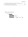
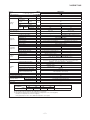
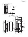
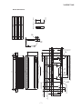
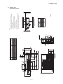
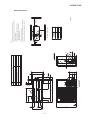
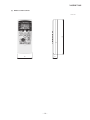
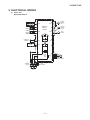
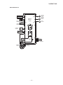
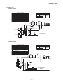
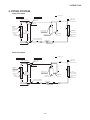
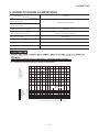
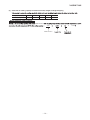
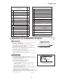
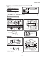
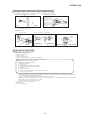
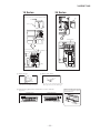
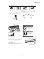
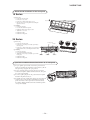
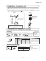
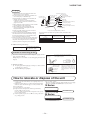
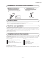
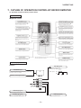
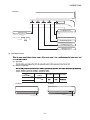
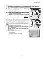

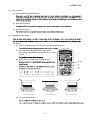
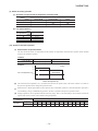
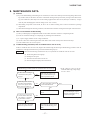
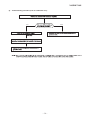
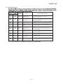
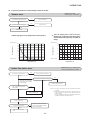
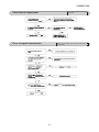
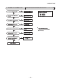
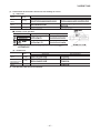
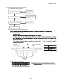
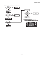
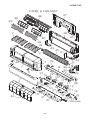
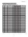
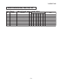

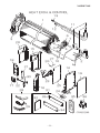
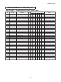
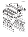
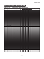
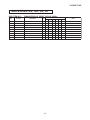
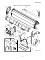
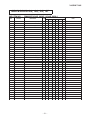
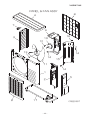
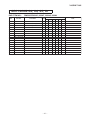
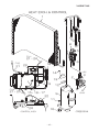
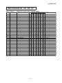
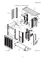
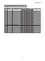
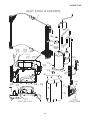
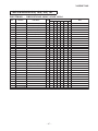
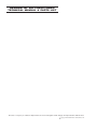

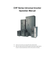

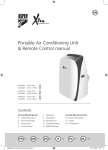

![ECT[DIN] [DIN] - Moore Industries International](http://vs1.manualzilla.com/store/data/005778735_1-93255c4f7d497ff32afcfe496e72d982-150x150.png)