1
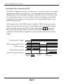
DOC. NO HHIS-WZ-PK-008 (02)
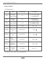
Accredited
by the RvA
ISO 9001/ISO 14001/OHSAS 18001(N/A)
REGISTERED FIRM
DNV Certification B.V., THE NETHERLANDS
RUN
plus
VECTOR INVERTER
INSTRUCTION MANUAL
plus
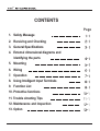
CONTENTS
Page
1. Safety Message
2. Receiving and Checking
3. General Specifications
4. External dimensional diagrams and
Identifying the parts
5. Mounting
6. Wiring
7. Operation
8. Using Intelligent Input Terminals
9. Function List
10. Protective functions
11. Trouble shooting Tips
12. Maintenance and Inspection
13. Option
plus
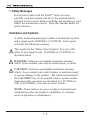
1. Safety Messages
For the best results with the N100plus Series inverter,
carefully read this manual and all of the warning labels
attached to the inverter before installing and operating it, and
follow the instructions exactly. Keep this manual handy for
quick reference.
Definitions and Symbols
A safety instruction(message) includes a hazard alert symbol
and a signal word, DANGER or CAUTION. Each signal
word has the following meaning:
This symbol is the "Safety Alert Symbol." It occurs with
either of two signal words : DANGER or CAUTION, as
described below
DANGER : Indicates a potentially hazardous situation
which, if not avoided, can result in serious injury or death.
CAUTION : Indicates a potentially hazardous situation
which, if not avoided, can result in minor to moderate injury,
or serious damage to the product. The situation described in
the CAUTION may, if not avoided, lead to serious results.
Important safety measures are described in CAUTION (as
well as DANGER), so be sure to observe them.
NOTE : Notes indicate an area or subject of special merit,
emphasizing either the product's capabilities or common
errors in operation or maintenance.
plus
CAUTION
Some drawings in this manual are shown with the protective or
shields removed in order to describe detail with more clarity.
Make sure all covers and shields are replaced before operating
this product.
This manual may be modified when necessary because of the
improvement of the product, modification, or changes in
specifications.
To order a copy of this manual, or if your copy has been
damaged or lost, contact your
representative.
Hyundai is not responsible for any modification of the product
made by the user, since that will void the guarantee.
plus
Index to Dangers and Cautions in This Manual
Installation-cautions for Mounting Procedures
CAUTION
Be sure to install the unit on flame-resistant
material such as a steel plate.
Otherwise, there is the danger of fire.
5-1
Be sure not to place any flammable materials
near the inverter.
Otherwise, there is the danger of fire.
5-1
Be sure not to let the foreign matter enter vent
openings in the inverter housing, such as wire
clippings, spatter from welding, metal shavings, dust, etc.
Otherwise, there is the danger of fire.
5-1
Be sure to install the inverter in a place which can
bear the weight according to the specifications in the text.
Otherwise, it may fall and cause injury to personnel.
5-1
Be sure to install the unit on a perpendicular wall
which is not subject to vibration.
Otherwise, it may fall and cause injury to personnel.
5-1
Be sure not to install or operate an inverter which
is damaged or has missing parts.
Otherwise, it may cause injury to personnel.
5-1
Lift the cabinet by the cooling fin. When moving the
unit, never lift by the plastic case or the terminal covers.
Otherwise, the main unit may be dropped causing damage
to the unit.
5-1
When mounting units in an enclosure, install a fan or
other cooling device to keep the intake air temperature
below 40 .
5-1
plus
CAUTION
Be sure to maintain the specified clearance
5-2
area around the inverter and to provide adequate
ventilation.
Otherwise, the inverter may overheat and cause eguipment
damage or fire.
Be sure to install the inverter in a well-ventilated
room which does not have direct exposure to
sunlight, a tendency for high temperature, high
humidity of dew condensation, high levels of dust,
corrosive gas, explosive gas, inflammable gas,
grinding-fluid mist, salt damage, etc.
Otherwise, there is the danger of fire.
5-2
plus
Wiring-Dangers for Electrical Practices and Wire
Specifications
DANGER
Be sure to connect grounding terminal.
Otherwise, there is a danger of electric shock and/or fire.
Wiring work shall be carried out only by qualified
personnel.
Otherwise, there is a danger of electric shock and/or fire.
6-2
6-2
Implement wiring after checking that the power
supply is off. You may incur electric shock and/or fire.
6-2
Do not connect wiring to an inverter or operate an
inverter that is not mounted according the instructions
given in this manual.
Otherwise, there is a danger of electric shock and/or
injury to personnel.
6-2
When wiring the emergency stop circuit, check the
wiring thoroughly before operation.
Otherwise, it may cause injury to personnel.
6-2
For 400V class, make sure to ground the supply
neutral.
Otherwise, there is a danger of electric shock.
6-2
plus
Wiring-Cautions for Electrical Practices
CAUTION
Be sure that the input voltage matches the inverter
specifications:
Single-phase 200 to 230 V 50/60Hz
Three-phase 200 to 230V 50/60Hz
Three-phase 380 to 460V 50/60Hz
Otherwise, there is the danger of injury and/or fire .
6-1
Be sure not to input a single phase to a three-phase
only type inverter.
Otherwise, there is the danger of fire.
6-1
Be sure not to connect an AC power supply to the
output terminals(U.V.W).
Otherwise, there is the danger of injury and/or fire.
6-1
Do not Run/Stop operation by switching ON/OFF
electromagnetic contactors on the primary or secondary
sides of the inverter.
Otherwise, there is the danger of fire.
6-1
To connect a braking resistor, follow the procedures
described in this manual.
Otherwise, there is the danger of fire.
6-1
plus
CAUTION
Fasten the screws with the specified fastening
torque. Check for any loosening of screws.
Otherwise, there is the danger of fire.
6-1
Be sure to install a fuse in the wire for each phase
of the main power supply to the inverter.
Otherwise, there is the danger of fire.
6-1
Do not perform a withstand voltage test of the
inverter.
Otherwise, it may cause semi-conductor elements
to be damaged.
6-1
To connect a braking resistor, braking resistor unit
or braking unit, follow the procedures in this manual.
Improper connection may cause a fire.
6-1
Do not connect or disconnect wires or connectors
while power is applied to the circuit.
Otherwise, it may cause injury to personnel.
6-1
plus
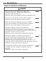
Dangers for Operations and Monitoring
DANGER
Be sure to turn on the input power supply after
closing the front case. While being energized, be
sure not to open the front case.
Otherwise, there is the danger of electric shock and/or fire.
7-1
Be sure not to operate the switches with wet hands.
Otherwise, there is the danger of electric shock.
7-1
While the inverter is energized, be sure not to touch
the inverter terminals even when the motor is stopped.
Otherwise, there is the danger of electric shock.
7-1
If the Retry Mode is selected, the motor may
suddenly restart during the trip stop. Do not approach
the machine(be sure to design the machine so that safety for
personnel is secure even if it restarts.)
Otherwise, it may cause injury to personnel and/or fire.
7-1
If the power supply is cut off for a short period of
time, the inverter may restart operation after the power
supply recovers if the command to operate is active.
If a restart may pose danger to personnel, so be sure to use
a lock out circuit so that it will not restart after power recovery.
Otherwise, it may cause injury to personnel.
7-1
The Stop Key is effective only when the stop function
is enabled. Be sure to prepare emergency stop key
separately.
Otherwise, it may cause injury to personnel.
7-1
plus
DANGER
After the operation command is given, if the
alarm reset is conducted, it will restart suddenly.
Be sure to set the alarm reset after verifying the
operation command is off.
Otherwise, it may cause injury to personnel.
7-1
7-1
Be sure not to touch the inside of the energized
inverter or to put any conductive object into it.
Otherwise, there is a danger of electric shock and/of fire.
plus
Cautions for Operations and Monitoring
CAUTION
The heat sink fins will have a high temperature.
Be careful not to touch them.
Otherwise, there is the danger of getting burned.
7-2
Install a holding brake separately if necessary.
Otherwise, there is the danger of accident.
7-2
Check the direction of the motor, any abnormal
motor vibrations or noise.
Otherwise, there is the danger of equipment damage.
7-2
The operation of the inverter can be easily changed
from low speed to high speed. Be sure check the
capability and limitation of the motor and machine
before operating the inverter.
7-2
If you operate a motor at a frequency higher than
the inverter standard default setting (60Hz), be sure
to check the motor and machine specifications with
the respective manufacturer. Only operate the motor at
elevated frequencies after getting their approval.
Otherwise, there is the danger of equipment damage.
7-2
All the constants of the inverter have been preset
at the factory.
Otherwise, there is the danger of equipment damage.
7-2
plus
Dangers and cautions for Troubleshooting
Inspection and Maintenance
DANGER
Wait at least five(5) minutes after turning off the
input power supply before performing maintenance
or an inspection.
Otherwise, there is the danger of electric shock.
12-1
Make sure that only qualified personnel will
12-1
perform maintenance, inspection, and part replacement.
(Before starting to work, remove any metallic objects from
your person(wrist watch, bracelet, etc.) Be sure to use tools with
insulated handles.
Otherwise, there is a danger of electric shock and/or injury to
personnel.
Never touch high-voltage terminals in the inverter.
Otherwise, there is a danger of electric shock.
12-1
The control PC board employs CMOS ICS.
Do not touch the CMOS elements.
They are easily damaged by static electricity.
12-1
Do not connect or disconnect wires, connectors, or
cooling fan while power is applied to the circuit.
Otherwise, it may cause injury to personnel.
12-1
Dangers for using
DANGER
Never modify the product.
Otherwise, there is a danger of electric shock and/or injury to
personnel.
plus
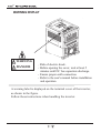
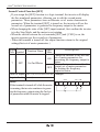
WARNING DISPLAY
WARNING
DANGER
Risk of electric shock.
Before opening the cover, wait at least 5
minutes until DC bus capacitors discharge.
Ensure proper earth connection.
Refer to the user's manual before installation
and operation.
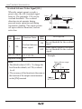
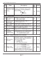
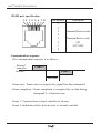
A warning label is displayed on the terminal cover of the inverter,
as shown in the figure.
Follow these instructions when handling the inverter.
plus
Do not Run/Stop operation by switching on/off electromagnetic
contactors (Mc0, Mc1) on the primary or secondary sides of the
inverter.
Operate the inverter by Run/Stop commanding [FW/RV].
Inverter
Motor Terminal Surge Voltage Suppression Filter (for the
400V class)
In a system using an inverter with the voltage control PWM system, a
voltage surge caused by the cable constants such as the cable length
(especially when the distance between the motor and inverter is 10m or
more) and cabling method may occur at the motor terminals. A
dedicated filter of the 400V class for suppressing this voltage surge is
available. Be sure to install a filter in this situation.
Input power disconnection
This inverter is not able to protect input power disconnection.
Be careful to connect the wires.
plus
In the cases below involving a general-purpose inverter, a large
peak current flows on the power supply side, sometimes destroying the
converter module.
The unbalance factor of the power supply is 3% or higher.
The power supply capacity is at least 10 times greater than the inverter
capacity(and the power supply capacity, 500kVA or more).
Abrupt power supply changes are expected.
some examples) Several inverters are interconnected with a short bus.
An installed leading capacitor opens and closes.
RC Value of the thermal Relay is 1.1 times greater than the
motor rated current. Also, RC Value is adjustable to the wiring
distance, but contacts us in this case.
Do not connect and disconnect the power supply more than
1/5(number / minute)
There is the danger of inverter damage.
When the EEPROM error E 08 occurs, be sure to confirm the
setting values again.
plus
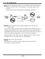
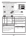
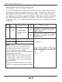
N100
INSTRUCTION MANUAL
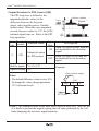
2. Receiving and checking
Inverter Specifications Label
Before installing and wiring, check the following
(1) Check the unit for physical damage that may have occurred
during shipping
(2) Verify that the package contains one inverter and one manual
after packing the N100plus inverter.
(3) Verify that the specifications on the labels match your purchase
order
Inverter model number
plus
Model : N100 -015LF
Motor capacity for this model
Power : 1.5kW/2HP
Power Input Rating: frequency,
voltage, phase
Input : 50Hz/60Hz 200 230V 3Ph
Output : 0.5-400Hz 200− 230V 3ph 7.0A
Output Rating: Frequency,
voltage, phase current
MFG NO :
HYUNDAI
Manufacturing codes:
Lot number, date, etc.
HEAVY INDUSTRIES CO., LTD.
Customer Service Center
052)230-8445/6
If any part of N100plus is missing or damaged, call for service immediately
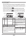
Model Number convention
The model number for a specific inverter contains useful information
about its operating characteristics. Refer to the model number legend
below:
N100plus - 015
H
Directive type :
E: CE directive, blank : UL directive
F
Configuration type
F:operator pannel equipped
Input voltage:
S: single phase 200V class
L: three-phase only 200V class
H: three-phase 400V class
Series name
Maximum applicable motor capacity
(4P, kW)
004: 0.4kW
007: 0.75kW
015: 1.5kW
022: 2.2kW
037: 3.7kW
2-1
plus
N100
INSTRUCTION MANUAL
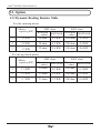
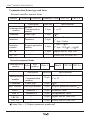
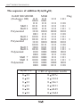
3. N100plus Inverter Standard Specifiations.
Model-specific tables for 200V and 400V class inverters
The following two tables are specific to N100plus inverters for the
200V and 400V class model groups. The table on page 3-3 gives
the general specifications that apply to both voltage class groups.
Footnotes for all specifications tables are on the next page.
200V Class Specifications
Item
plus
Model N100
plus
plus
plus
plus
plus
plus
plus
plus
N100 N100 N100 N100 N100 N100 N100 N100
-004SF -007SF -015SF -004LF -007LF -015LF -022LF -037LF
series
kW
0.4
0.75
1.5
0.4
0.75
1.5
2.2
3.7
HP
1/2
1
2
1/2
1
2
3
5
1.1
1.9
3.0
1.1
1.9
3.0
4.2
6.1
Applicable motor size *2
Rated capacity(200V)kVA
Rated input voltage
There-phase (3-wires)
200 to 230V 10%,
50/60 Hz 5%
Single-phase
200 to 230V 10%,
50/60 Hz 5%
Rated output voltage *3
3-phase 200 to 230V (corresponding to input voltage)
Rated output current(A)
3.0
5.0
Starting torque
(with sensorless vector
control selected)
Weight (kg)
3.0
5.0
7.0
11.0
17.0
200% or more
resistor,
Dynamic braking without
from 50/60Hz
approx. % torque,
short time stop *5 with resistor
DC braking
7.0
approximately
100%
approximately
20 40%
approximately
150%
approximately
100%
Variable operating frequency, time and braking force
1.2
1.2
3-1
1.5
1.2
1.2
1.5
1.5
2.0
plus
N100
INSTRUCTION MANUAL
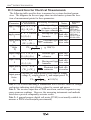
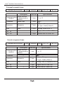
400V Class Specifications
Item
N100plus
-004HF
N100plus
-007HF
N100plus
-015HF
N100plus
-022HF
N100plus
-037HF
kW
0.4
0.75
1.5
2.2
3.7
HP
1/2
1
2
3
5
1.1
1.9
3.0
4.2
6.1
Model N100plus series
Applicable motor
size *2
Rated capacity(200V)kVA
3-phase : 380 to 460V 10%,
50/60Hz 5%
Rated input voltage
Rated output voltage *3
Rated output current(A)
3-phase 380 to 460V (corresponding to input voltage)
1.8
Starting torque
(with sensorless vector
control selected)
Weight(kg)
4.8
7.2
9.2
200% or more
approximately
100%
approximately
100%
Dynamic braking without resistor,
approx. % torque, from 50/60Hz
short time stop *5 with resistor
DC braking
3.4
approximately
20 40%
approximately
100%
Variable operating frequency, time and braking force
1.2
1.5
3-2
1.5
2.0
2.0
plus
N100
INSTRUCTION MANUAL
General Specifications
The following table applies to all N100plus inverters.
General Specifications
Item
Protective housing *1
Enclosed type(IP20)
Space vector PWM control
Control method
Output frequency range *4 0.01 to 400Hz
Frequency accuracy
Digital command : 0.01% of the maximum frequency
Analog command : 0.1% of the maximum frequency
Frequency setting
resolution
Digital : 0.01Hz(100Hz and less), 0.1Hz
(100Hz or more)
Analog : Max. Setting frequency / 500(DC 5V input),
max. setting frequency / 1000(DC 10V, 4 20mA)
Any base freguency setting possible between 0Hz
Volt./ Freq. Characteristic and 400Hz.
V/F control (constant torque, reduced torque).
Overload current rating
150%, 60 seconds
Acceleration/deceleration 0.1 to 3000sec., (linear accel. / decel. s-curve,
u-curve), second accel. / decel. setting available
time
Operator panel Up and Down keys / Value settings
Input signal
Freq- Potentiometer Analog setting via potentiometer.
setting
External signal 1W, 1 to 2 variable resistor
DC 0 5V
DC 0 10V, 4 20mA(Input Impedonce 10 )
FWD/ Operator panel Run/Stop(Forward/Reverse run change by command)
REV
Run External signal Forward run/stop, Reverse run/stop set by terminal
assignment (NC/NO)
Intelligent input
terminal
FW(forward run command), RV(reverse run
command), CF1 CF4(multistage speed setting),
JG(jog command), 2CH(2-stage accel./decel.
command), FRS(free run stop command),
EXT(external trip), USP (unattended startup),
SFT(soft lock), AT(analog current input select
signal), RS(reset), SET(2nd setting selection)
3-3
plus
N100
INSTRUCTION MANUAL
General Specifications
RUN(run status signal), FA1 (frequency arrival
Intelligent output signal), FA2 (setting Frequency arrival signal),
OL(overload advance notice signal), OD(PID error
terminal
deviation signal), AL(alarm signal)
Analog meter (DC0 10V full scale, Max. 1mA)
Frequency monitor Analog output frequency, Analog output current and
Analog output voltage signals selectable.
OFF for inverter alarm(normally closed contact
Alarm output contact output) (Transition to ON for alarm)/Intelligent
output Terminal
AVR function, curved accel./decel. profile, upper and
lower limiters, 16-stage speed profile, fine adjustment
of start frequency, carrier frequency change (0.5 to
16Khz), frequency jump, gain and bias setting, process
jogging, electronic thermal level adjustment, retry
Other functions
function, trip history monitor, 2nd setting selection,
auto tuning, V/f characteristic selection, automatic
torque boost, frequency coversion display, USP
function
Over-current, over-voltage, under-voltage, overload,
extreme high/low temperature, ground fault
detection, internal communication error, external
Protective function
trip, EEPROM error, USP error, instantaneous
power failure, output short-circuit detection.
-10 to 50 (If ambient temperature exceed 40 ,
Ambient temperature reduce the carrier frequency to 2.1kHz or less and
the rated current to 80% or less)
60 (short-term temperature during
Storage temperature -20
transport)
Operating
Environment
Output signal
Item
Ambient humidity
Vibration
Location
Options
90% RH or less (no condensing)
5.9m/s2 (0.6G), 10 to 55Hz(conforms to the test
method specified in JIS C0911)
Altitude 1,000m or less, indoors(no corrosive gasses
or dust)
Remote operator unit, cable for operator, braking
unit, braking resistor, AC reactor, DC reactor,
noise filter.
3-4
plus
N100
INSTRUCTION MANUAL
Footnotes for the preceding tables :
1. The protection method conforms to JEM 1030.
2. The applicable motor refers to HYUNDAI standard 3-phase motor
(4-pole). To use other motors, care must be taken to prevent the rated
motor current(50/60Hz) from exceeding the rated output current of the
inverter.
3. The output voltage decreases as the main supply voltage decreases
(except for use of the AVR function). In any case, the output voltage
cannot exceed the input power supply voltage.
4. To operate the motor beyond 50/60Hz, consult the motor mamanufacturer
about the maximum allowable rotation speed.
5. The braking torque via capacitive feedback is the average decelection
torque at the shortest deceleration (stopping from 50/60Hz as indicated).
It is not continuous regenerative braking torque. And, the average
deceleration torque varies with motor loss. This value decreases when
operating beyond 50 Hz. If a large regenerative torque is required, the
optional regenerative braking resistor should be used.
6. Control method setting A31 to 2 (sensorless vector control) Selected,
set carrier frequency setting b11 more than 2.1kHz.
3-5
plus
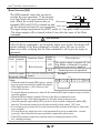
N100
INSTRUCTION MANUAL
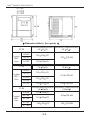
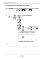
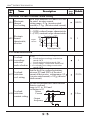
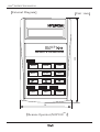
4. External Dimension Diagrams and Identifying the parts
Main Physical Features
Display part
Front cover
Control key
Terminal cover(Note)
Communication
port
Main circuit
terminal
Mounting hole
Cooling fan
Fan cover
Ground Terminal
Removing terminal cover :
Use a hand and press on the terminal cover surface to remove it.
Control wiring can be possible by removing terminal cover.
Note) Do not press excessive pressure.
Otherwise, the cover may be damaged.
4-1
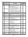
plus
N100
INSTRUCTION MANUAL
Front cover
Bolt
Wiring
cover
Use a screwdriver to loosen the Bolt on the front cover.
Notice the wiring cover that lifts out to allow full access to the terminals for
wiring.
After removing terminal cover, locate the recessed retention screw on the left
side main front panel.
Use a small screwdriver to loosen the screw, swing the door around to the
left to reveal the internal components of the drive.
4-2
plus
N100
INSTRUCTION MANUAL
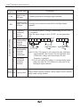
Inverter Dimensions for Mounting
The N100plus Series inverters have a digital operator as a standard and
contains all the elements for monitoring and setting parameters.
The optional remote operator may be available for remote operation.
Locate the applicable drawing on the following pages for your inverter.
Dimensions are given in millimeters (inches) format.
004SF/LF
007SF/LF
004HF
015SF/LF
022LF
007HF
015HF
4-3
plus
N100
INSTRUCTION MANUAL
037LF
022HF
037HF
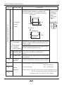
Dimension table by the capacity
TYPE
004SF
1-phase
200V
class
External dimension(mm) Installation dimension(mm)
(W H. )
(W H D)
115 130 135
007SF
015SF
TYPE
105 120,M4
115 130 155
External dimension(mm) Installation dimension(mm)
(W H D)
(W H. )
004LF
3-phase
200V
class
007LF
015LF
022LF
037LF
TYPE
004HF
3-phase
400V
class
007HF
015HF
022HF
037HF
115 130 135
105 120,M4
115 130 155
150 130 155
140 120,M4
External dimension(mm) Installation dimension(mm)
(W H D)
(W H. )
115 130 135
105 120,M4
115 130 155
150 130 155
4-4
140 120,M4
plus
N100
INSTRUCTION MANUAL
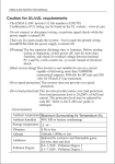
5. Installation
Choosing a Mounting Location
CAUTION
Be sure to install the unit on flame-resistant material such as a steel plate.
Otherwise, there is the danger of fire.
Be sure not to place any flammable materials near the inverter.
Otherwise, there is the danger of fire.
Be sure not to let the foreign matter enter vent openings in the inverter
housing, such as wire clippings, spatter from welding, metal shaving, dust,
etc.
Otherwise, there is the danger of fire.
Be sure to install the inverter in a place which can bear the weight
according to the specifications in the text
Otherwise, it may fall and cause injury to personnel.
CAUTION
Be sure to install the unit on a perpendicular wall which is not subject to
vibration.
Otherwise, it may fall and cause injury to personnel.
Be sure not to install or operate an inverter which is damaged or has
missing parts.
Otherwise, there is the danger of fire.
Be sure to install the inverter in a well-ventilated room which does not have
direct exposure to sunlight, a tendency for high temperature, high humidity
or dew condensation, high levels of dust, corrosive gas, explosive gas,
inflammable gas, grinding fluid mist, salt damage, etc.
Otherwise, there is the danger of fire.
5-1
plus
N100
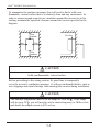
INSTRUCTION MANUAL
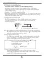
To summarize the cautions messages-You will need to find a solid, nonflammable, vertical surface that is a relaticely clean and any envirnment. In
order to ensure enough room for air circulation around the inverter to aid in
cooling, maintain the specified clearance around the inverter specified in the
diagram.
10cm
minimum
8cm
minimum
Air flow
12cm
minimum
Wall
10cm
minimum
CAUTION
Solid, nonflammable, vertical surface
Before proceeding to the wiring section, it's good time to temporarily
cover the inverter's ventilation openings. It will prevent harmful debris such as
wire clippings and metal shavings from entering the inverter during installation
CAUTION
The ambient temperature must be in the range of-10 to 40 . If the range
will be up to 50 , you will need to set the carrier frequency to 2kHz or less
and derate the output current to 80% or less.
5-2
plus
N100
INSTRUCTION MANUAL
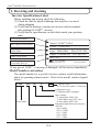
6.Wiring
DANGER
Be sure to ground the unit.
Otherwise, there is a danger of electric shock and/or fire.
Wiring work shall be carried out only by qualified personnel.
Otherwise, there is a danger of electric shock and/or fire.
Implement wiring after checking that the power supply is off.
You may incur electric shock and/or fire.
Do not connect wiring to an inverter or operate an inverter that is not mounted
according the instructions given in this manual.
Otherwise, there is a danger of electric shock and/or injury to personnel.
CAUTION
Be sure to that input voltage matches the inverter specifications.
Otherwise, there is a danger of electric fire and/or injury to personnel.
Be sure not to connect an AC power supply to the output terminals.
Otherwise, there is a danger of electric fire and/or injury to personnel.
Be sure not to connect a resistor to the DC-link terminal(P, PB).
Otherwise, there is a danger of fire
Remarks for using earth leakage circuit breakers in the main supply.
Otherwise, there is a danger of fire.
For motor leads, earth leakage breakers and electromagnetic contactors, be
sure to size these components properly.
Otherwise, there is a danger of fire.
Do not RUN/STOP operation by switching ON/OFF electromagnetic
contactors on the primary or secondary sides of the inverter.
Otherwise, there is a danger of fire.
Fasten the screws with the specified fastening torque.
Otherwise, there is a danger of fire.
6-1
plus
N100
INSTRUCTION MANUAL
6.1 Wiring the main circuit
You will connect main circuit terminal wiring to the input of the inverter.
For wiring, open the front cover and wiring cover.
plus
Ex)N100 -004LF
R
S
T P RB U V W
Inverter
Thermal
Relay
Thermal
Relay
Motor
Motor
Power supply
Motor
Always connect the power input terminals R, S, and T to the power supply.
Be sure to install thermal relay individually when one inverter operates
several motors.
Never connect P, RB, to R, S, T, or U, V, W.
Otherwise, there is the danger of equipment damage.
6-2
plus
N100
INSTRUCTION MANUAL
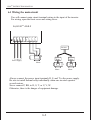
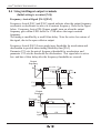
NOTE1) Install mechanically interlocked switches Mc1 and Mc2 in case of
exchange by using commercial power supply and inverter.
Mc1
MCCB
Power
supply
Mc0
Inverter
R
U
S
V
T
W
Mc2
Motor
NOTE2) Install an earth leakage breaker(or MCCB) on the power supply side
of the inverter. If the wiring distance between inverter and motor
(10m and more) is long, the thermal relay may be incorrectly operated
on the effect of high-frequency noise. Install the AC reactor on the
inverter output side or use the current sensor.
NOTE3) Make sure to ground the ground terminal according to the local
grounding code. Never ground the N100plus inverter in common with
welding machines, motors, or other electrical equipment.
When several inverters are used side by side, ground each unit as shown in
examples. Do not the ground wires.
POOR
GOOD
Inverter
Inverter
Inverter
Inverter
Inverter
Inverter
6-3
Ground bolt
plus
N100
INSTRUCTION MANUAL
6.2 Wiring the control circuit
control circuit terminal
CM1 6
5
4
3
2
1 P24
H O OI L FM CM2 12 11
Multi-speed1
Reverse command
Forward command
External power supply
for input signal
4
3
2
1 P24
H
Frequency arrival signal
Multi-speed2
5
Run
2-stage speed
CM1 6
Input common
Reset
Example of control circuit terminal
O OI L FM CM2 12 11
2
1
V.R
3
RY
Frequency
command
1
2
Frequency meter
FA2
RY
FA1
27 VDC
50 max
Note1) When an output intelligent terminal is used, be sure to install a surge
absorbing diode in parallel with relay. Otherwise, the surge voltage created
when the relay goes ON or OFF may damage the output intelligent terminal
circuit.
6-4
plus
N100
INSTRUCTION MANUAL
Note2) Use a twisted and shielded wire for the signal line, and cut the shielded
covering as shown in the diagram below. Make sure that the length of the
signal line is 20 meters or less
Insulate
No grounding necessary
²
Connect to the common terminal[CM1] and [L] of the inverter
Note3) When the frequency setting signal is turned on and off with a contact, use
a relay which will not cause contact malfunctions, even with the extremely
weak currents and voltages.
Note4) Use relays which do not have contact defects at 24 V DC, 3mA for the
other terminals.
Note5) Separate the main circuit wiring from the relay control circuit wiring.
If they must cross, be sure that they cross at a right angle.
Main circuit power line
(R,S,T,U,V,W,P,PB )
Right angle
Signal input line
(CM1,6,5,4,3,2,1,P24,H,O,OI,L, FM,CM2,12,11)
Seterate by 10cm or more
Note6) Do not short circuit the terminals H-L of the control circuit.
Note7) Do not short circuit the terminals H-OI of the control circuit.
6-5
plus
N100
INSTRUCTION MANUAL
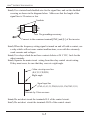
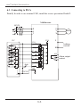
6.3 Connecting to PLCs
Note 1) In order to use terminal CM1, install the reverse prevention Diode D
N100 Inverter
MCCB
R
S
T
U
V
W
P24
PLC
S
P24
1
6
motor
P
braking
resistor
RB
2
5
3
4
4
3
5
2
6
diode
(D)
AL0
AL1 Alarm output
AL2 contact
1
CM1
DC24V
COM
6-6
plus
N100
INSTRUCTION MANUAL
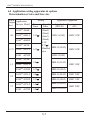
6.4 Application wiring apparatus & options
Determination of wire and Fuse size
Motor
Output Application
(kw) Inverter Model
Wiring
Power
Lines
N100plus-004SF
04
plus
N100 -004LF
1.25
N100plus-004HF
plus
N100 -007SF
0.75 N100plus-007LF
1.25
Signal
Lines
Applicable equipment
Leakage braker Magnetic contactor
(MC)
(MCCB)
(Note5)
(Note6)
HBS-33(5AT)
(Note7)
(Note8)
0.140.75
Shielded HBS-33(10AT)
wire
N100plus-007HF
HMC 10W
HMC 10W
HBS-33(5AT)
plus
N100 -015SF
1.5
2.2
3.7
plus
2.0
HBS-33(15AT)
N100 -015LF
HMC 10W
N100plus-015HF
1.25
HBS-33(10AT)
N100plus-022LF
2.0
HBS-33(20AT)
HMC 20W
N100plus-022HF
1.25
HBS-33(10AT)
HMC 10W
N100plus-037LF
3.5
HBS-33(30AT)
plus
N100 -037HF
HMC 20W
HBS-33(15AT)
2.0
6-7
plus
N100
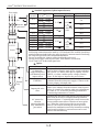
INSTRUCTION MANUAL
Power supply
Standard Apparatus(3-phase input reference)
Wiring
Applicable equipment
Motor
Inverter model
output(kw) (N100plus Series) Power lines Signal lines Fuse(class J) rated 600V
plus
Fuse
0.4
Electromagnetic contact
0.75
1.5
R S T
L1 L2 L3
P
Inverter
RB
T1 T2 T3
U V W
Thermal
relay
Motor
2.2
3.7
0.4
0.75
1.5
2.2
3.7
N100 -004SF
plus
N100 -004LF
plus
N100 -007SF
plus
N100 -007LF
plus
N100 -015SF
plus
N100 -015LF
plus
N100 -022LF
plus
N100 -037LF
plus
N100 -004HF
plus
N100 -007HF
plus
N100 -015HF
plus
N100 -022HF
plus
N100 -037HF
5A
1.25
0.14
2.0
0.75
shielded
wire
0.14
2.0
15A
20A
30A
3.5
1.25
10A
0.75
shielded
wire
5A
10A
15A
<Note>
Field wiring connection must be made by a UL listed and CSA certified, closed-loop
terminal connector sized for the wire gauge involved. Connector must be fixed using
the crimp tool specified by the connector manufacturer.
Be sure to consider the capacity of the circuit breaker to be used.
Be sure to use bigger wires for power lines if the distance exceeds 20m.
Use 0.75mm2 wire for the alarm signal wire.
Option
Name
Function
Input-side AC reactor This is useful when harmonic suppression measures
must be taken. when the main power voltage unbalance
for harmonic
suppression/power rate exceeds 3% and the main power capacity exceeds
coordination/power 500kVA, or when a sudden power voltage variation
occurs. It also helps to improve the power factor.
improvement
Reduces the conductive noise on the main power wires
generated from the main power supply. Connect to the
EMI filter
inverter primary side(input side).
This is installed between the inverter and the motor to
reduce noise radiated from the main the control power
Output-side noise wiring. It is useful for reducing radio-wave disturbance
filter
in a radio or TV set and for preventing malfunction
of measuring instruments or sensors.
AC reactor for
vibration
reduction/thermal
relay malfunction
prevention
Vibration may increases when driving a general-purpose
motor with an inverter as compared with operation on
commercial power. Connecting this reactor between the
inverter and the motor allows reduction of motor pulsation. When the wirung between the inverter and the
motor is 10m or more, inserting the reactor prevents
thermal relay malfunction caused by harmonics resulting
from incerter switching. A current sensor can be used
instead of the thermal relay
6-8
plus
N100
INSTRUCTION MANUAL
Note 1) The applicable equipment is for HYUNDAI standard four pole
squirrel cage motor.
Note 2) Be sure to consider the capacity of the circuit breaker to be used.
Note 3) Be sure to use larger wire for power lines if the distance exceeds 20m.
Note 4) Be sure to use an grounding wire same size of power line or similar.
Note 5) Use 0.75mm2 wire for the alarm signal terminal.
Note 6) Use 0.5mm2 wire for the control curcyit terminal.
Classify the detective current of the earth leakage breaker depending on the
total distance between the inverter and the motor.
Length
100m and less
300m and less
800m and less
Detective current(mA)
30
100
200
Note1) When using CV wire and metal tube the leakage current is around
30mA/km.
Note2) The leakage current becomes eight times because IV wires have a
high dielectric constant. Therefore, use an one class earth leakage
breaker according to the above table.
6-9
plus
N100
INSTRUCTION MANUAL
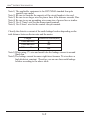
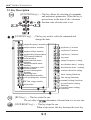
6.5 Terminal array & Terminal function
(1) Terminal array
<Main circuit>
Main circuit terminal
R
S
P RB U
T
V W
CASE
Model
Screw
Width(mm)
N100plus
004SF
015SF
004LF
037LF
004HF
037HF
M4
11
<Control circuit>
Control circuit terminal
CM1 6 5 4 3 2
1 P24 H O OI L FMCM212 11 AL0AL1AL2
* Use the "-"type skew driver
6-10
Width(mm)
Model Screw
diameter
N100plus
Control Control :
004SF
M2
3.5
015SF
Alarm Alarm:
004LF
M3
5.08
037LF
004HF
037HF
plus
N100
INSTRUCTION MANUAL
(2) Terminal Function
Main circuit Terminal
Terminal Terminal
Function
symbol name
power Connect the input
R, S, T Main
supply input power supply 220V,
440V
U, V, W Inverter
Connect the MOTOR
output
R S T P RB U V W
External Connect the braking
RB, P resistor
connection resistor(option)
Ground
Connect the Die-casting
(to prevent electric
shock and reduce noise)
M
Power
supply
Control circuit Terminal
Signal Terminal
symbol
P24
6
5
Input
signal
4
3
2
1
Terminal name
Power terminal for input signals
Forward run command(FW), Reverse run
command(RV), multi-speed commands1-4
(CF1-4), 2-stage accel/decel (2CH),
Reset(RS), second control function setting
(SET), terminal software lock(SFT),
unattended start protection(USP),
current input selection(AT), jogging
operation(JG), External trip(EXT)
Terminal function
24VDC
35mA
10%,
contact input :
Close : ON
(operating)
Open : OFF
(stop)
minimum ON
TIME :12ms
or more
Common terminal for input or monitor
CM1 signal
Monitor
signal
FM
Output frequency meter, output current
meter, output voltage meter
CM1
Common terminal for input or monitor
signal
6-11
Analog frequency
meter
plus
N100
INSTRUCTION MANUAL
Control circuit Terminal
Signal Terminal
symbol
Terminal function
Power supply for frequency setting
0 5VDC
O
Voltage frequency command signal
0 5VDC(standard),
0 10VDC, input
impedance 10
OI
Current frequency command signal
H
Frequency
command
signal
Terminal name
Common terminal for frequency command 4 20mA, input impedance
250
Intelligent output terminal:
11 run status signal(RUN), frequency arrival
signal(FA1) set frequency arrival signal
(FA2), overload advance notice signal(OL),
12 PID error deviation signal(OD), alarm
signal(AL)
L
Output
signal
CM2 Common terminal for output signal
Alarm output signals :
at normal status, power off
Trip al: AL0-AL2 (closed)
arm
at abnormal status
output AL2
: AL0-AL1(closed)
signal
AL0 AL1 AL2
Contact rating:
AC 250V 2.5A
(resistor load)
0.2A
(inductor load)
DC 30V 3.0A
(resistor load)
0.7A
(inductor load)
NOTE1) The USP function prevents the automatic startup immediately after
powerup.
NOTE2) The reset terminal can be used in the normally open(NO)contact state.
The contact can be inverted by using the parameter C 07 to C 12
NOTE3) The intelligent output terminal has several functions which you can
assign individually to three physical logic outputs.
NOTE4) The output terminal [11][12] is the normally open(NO) contact.
The contact logic can be inverted by using the parameter C 15 C 06
6-12
plus
N100
INSTRUCTION MANUAL
7. Operation
DANGER
Be sure to turn on the input power supply after closing the front case.
While being energized, be sure not to open the front case.
Otherwise, there is the danger of electric shock
Be sure not to operate the switches with wet hands.
Otherwise, there is the danger of electric shock.
While the inverter is energized, be sure not to touch the inverter terminals
even when the motor is stopped.
Otherwise, there is the danger of electric shock.
If the Retry Mode is selected, the motor may suddenly restart during the trip
stop. Do not approach the machine(be sure to design the machine so that
safety for personnel is secure even if it restarts).
Otherwise, it may cause injury to personnel.
If the power supply is cut off for a short period of time, the inverter may
restart operation after the power supply recovers if the command to operate
is active. If a restart may pose danger to personnel, so be sure to use a
lock-out circuit so that it will not restart after power recovery.
Otherwise, it may cause injury to personnel.
The stop key is effective only when the stop function is enabled. Be sure to
enable the key sepatately from the emergency stop.
Otherwise, it may cause injury to personnel.
Arter the operation command is given, if the alarm reset is conducted, it will
restart suddenly. Be sure to set the alarm reset after verifying the operation
command is off.
Otherwise, it may cause injury to personnel.
Be sure not to touch the inside of the energized inverter or to put any
conductive object into it.
Otherwise, there is a danger of electric shock and/or fire.
plus
N100
INSTRUCTION MANUAL
CAUTION
The heat sink fins will have a high temperature. Be careful not to touch
them.
Otherwise is the danger of getting burned.
The operation of the inverter can be easily changed from low speed to high
speed. Be sure check the capability and limitations of the motor and machine
before operating the inverter.
Otherwise, there is the danger of injury.
If you operate a motor at a frequency higher than the inverter standard
default setting 60Hz, be sure to check the motor and machine specifications
with the respective manufacturer.
Otherwise, there is the danger of equipment damage.
Install a holding brake separately if necessary.
Otherwise, there is the danger of accident.
Check the direction of the motor, abnormal motor vibrations, and noise.
Otherwise, there is the danger of equipment damage.
7.1 Before the powerup test
Prior to the test run, check the following
(1) Make sure that the power lines (R, S and T) and output terminals
(U, V and W)are connected correctly.
Otherwise, there is a danger of inverter damage
(2)Make sure that there are no mistakes in the signal line connections
Otherwise, it may be incorrect operation of the inverter.
(3) Make sure that the inverter earth terminal is grounded.
Otherwise, there is a danger of electric shock.
(4) Make sure that terminals other than those specified are not grounded.
Otherwise, it may be incorrect operation of the inverter.
(5) Make sure that there are no short-circuits caused by stay pieces of
wire, solderless terminals or other objects left from wiring work.
Also, make sure that no tools have been left behind.
Otherwise, there is a danger of inverter breakage.
(6) Make sure that the output wires are not short-circuited of grounded.
Otherwise. there is a danger of inverter damage.
plus
N100
INSTRUCTION MANUAL
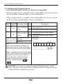
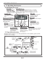
7.2 Powerup test
The following instructions apply to the power up test.
The operation from the standard operator Frequency setting, Run and
stop command are controlled as follows :
Frequency setting select the potentiometer STOP/RUN : select the
RUN and STOP key
MCCB
R
S
T
Power
supply
400V class
3-phase 380
460V, 50/60Hz
200V class
3-phase 200
230V , 50/60Hz
200V class
1-phase 200
230V, 50/60Hz
1
2
3
4
5
6
CM1
P24
H
0
0I
L
FM
U
V
W
P
RB
AL0
AL1
AL2
11
CM2
Motor
Regenerative
braking resistor
}
Alarm output :
(AT normal status,
power off : AL0-AL2 :ON
AT abnormal status
: AL0-AL1 :ON
12
Ground
ACTION (Digital operator control)
(1) Turn On the power supply by turning ON MCCB.
The [POWER] LED will illuminate.
(2) After checking that the potentiometer Enable LED is ON, set the frequency
by rotating the potentiometer.
(3) After checking that the RUN Enable LED is ON, press the RUN key.
(4) The inverter starts running [RUN] LED is ON.
(5) Monitor the output frequency in the monitor mode d 01
STOP key to stop the motor rotation.
(6) Press the RESET
plus
N100
INSTRUCTION MANUAL
Check the following before and during the powerup test.
CAUTION
Is the direction of the motor correct?
Otherwise, there is the danger of equipment damage.
Were there any abnormal motor vibrations or noise?
Otherwise, there is the danger of equipment damage.
NOTE1) 1. Did the inverter trip during acceleration or deceleration?
2. Were the rpm and frequency meter readings as expected?
If the over current or over voltage trip is occurred of the power up
test, set the acceleration or deceleration time longer.
Factory setting
Maximum frequency : 60Hz
Rotation direction : forward run
plus
N100
INSTRUCTION MANUAL
8. Using intelligent terminals
8.1 Intelligent terminal lists
Terminal Terminal name
symbol
SWF Switch
ON (closed):Forward run
OFF(open): stop
SWR Switch
ON (closed):Reverse
CM1
run
OFF(open): stop
FW Forward
(0) RUN/STOP
terminal
Intelligent Input Terminal(1 6)
RV Reverse
(1) RUN/STOP
terminal
CF4
(5)
JG(6) Jogging
SWR SWF
RV
Output freguency
Forward
Reverse
FW
2
1
SWF ON OFF OFF
SWR OFF ON OFF
When SWF and SWR commands are active at the same
time, the inverter stops
Frequency
0-speed
Default Terminal
1 (Hz) 3-speed
RS 2CHCF2 CF1 RV FW
CF1 Multi-speed
(2) frequency
commanding
CF2 terminal
2
(3)
CF3
(4)
Description
2-speed
1-speed
Switch
3
4
CF1
CF2
FW
RV
ON
ON
ON
ON
ON
ON
ON
CM1 6 5 4 3 2 1 L
setting
Terminal1 : FW
Terminal2 : RV
Terminal3 : CF1
Terminal4 : CF2
Terminal5 : 2CH
Terminal6 : RS
[4-Stage speed]
Jogging operation
You may change the setting value when only one inverter
SET Second control connects two motors(output frequency setting, acceleration/
deceleration time setting, manual torque boost setting, electr(7)
function
onic thermal setting, motor capacity setting, control method)
2CH 2-stage acceler- The acceleration or deceleration time is possible to change
(8) ation/deceleration considering the system.
The inverter stops the output and the motor enters the freeFRS Free-run stop
run state.(coasting)
(9)
EXT External trip
It is possible to enter the external trip state.
(10)
USP Unattended start Restart prevention when the power is turned on in the RUN
(11) prevention
state.
The data of all the parameters and functions except the output
SFT Terminal softfrequency is locked.
(12) ware lock
AT Current input
The [AT] terminal selects whether the inverter uses the voltage
(13) selection
[O] or current [OI] input terminals for external frequency control.
RS
If the inverter is in Trip Mode, the reset cancels the Trip Mode.
(14) Reset
plus
N100
INSTRUCTION MANUAL
Terminal
symbol
Terminal name
CM1
Signal source
for input
P24
External power
supply terminal External power connection terminal for intelligent input
terminals.
for input
Frequency commanding
Frequency
H command
power
terminal
Description
Common terminal for intelligent input terminals.
The External frequency voltage commanding is 0 to 5VDC
as a standard.
When the input voltage is 0 to 10VDC, use the parameter
A65
H 0 0I L
H 0 0I L
H 0 0I L
Frequency
commanding
0 terminal
(voltage
VRO
0~10VDC
4~20
commanding)
(1 ~ 2 )
input impedance input impedance
Frequency
0 5VDC
10
250
commanding
terminal
Note1) If the [AT] option is not assigned to any intelligent
0I
(current
input terminal, then inverter use the algebraic sum
command)
of both the voltage and current input for the
frequency command.
Frequency
2) If you use either the voltage or current analog input,
L command
make sure that the [AT] function is allocated to an
common
intelligent input terminal.
terminal
Monitor
terminal FM
Frequency monitor
Analog output frequency monitor/ analog output current monitor/
analog output voltage monitor
plus
N100
INSTRUCTION MANUAL
Terminal
symbol
Description
Terminal name
Frequency arrival [FA1][FA2] signals is indicated
when the output frequency accelerates and
decelerates to arrive at a constant frequency.
Frequency
F01 set value
Intelligent output terminal (11, 12)
FA1
(1)
FA2
(2)
Frequency
arrival
signal
ON at
constant
frequency
FA1
Time
FA2
Output terminal
specification
open-collector
output
27V DC max
50 max
CM2 12
11
RY
Frequency
Thresholds
C21
C22
ON at target
frequency
RUN
(0) Run signal
Time
When the [RUN] signal is selected, the inverter
outputs a signal on that terminal when it is in
the RUN mode.
Overload
When the output current exceeds a preset value,
notice signal the [OL] terminal signal turns on.
OL
advance
(3)
OD PID control error When the PID loop error magnitude the
(4) deviation signal preset value, the [OD] terminal signal
turns on.
AL
Alarm signal
(5)
CM 2
Common
terminal
AL 0
AL 1
AL 2
Alarm
terminals
The inverter alarm signal is active when a fault
has occurred.
Common terminal for intelligent output terminal
At normal status, power off(initial setting value)
: Al0 - AL1(closed)
At abnormal status
: AL0 - AL2(closed)
Contact rating : 250V AC 2.5A(resistor 1oad) 0.2A(inductor load)
30V DC 3.0A(resistor 1oad) 0.7A(inductor load)
(minimum 100V AC 10mA, 5V DC 100mA)
plus
N100
INSTRUCTION MANUAL
8.2 Monitor terminal function
Terminal Name : Monitor terminal [FM] (analog)
The inverter provides an analog output terminal primary for frequency
monitoring on terminal [FW] (output frequency, Output current, and output
voltage monitor signal).
Parameter C17 selects the output signal data.
When using the analog motor for monitoring, use scale reactor C18 and C19 to
adjust the [FM] output so that the maximum frequency in the inverter corresponds to full-scale reading on the motor.
(1) output frequency monitor signal
The [FM] output duty cycle varies with the inverter output frequency.
The signal on [FM] reaches full scale when the inverter outputs the
maximum frequency.
CM1 FM CM2
10V
M
0~10V
1
full-scale maximum T=4
(constant)
Note) This is dedicated indicator, so that it cannot be used as a line speed signal.
The indicator accuracy after adjustment is about 5% (Depending on the
meter, the accuracy may exceed this value)
(2) output current monitor signal
The [FM] output duty cycle varies with the inverter output current to the
motor. The signal on [FM] reaches full scale when the inverter output
current reaches 200% of the rated inverter current.
The accuracy of the current reaches approximately 10%
inverter output current (measured) : Im
monitor display current
: Im'
inverter rated current
: Ir
Im' - Im
Ir
100 <
=
10%
(3) output voltage monitor signal
The [FM] output duty cycle varies with inverter output voltage.
The signal on [FM] reaches full scale when the inverter output voltage
reaches 100% of the rated inverter voltage.
plus
N100
INSTRUCTION MANUAL
8.3 Intelligent Input Terminal Function
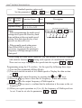
Forward Run/Stop[FW] and Reverse Run/Stop Command[RV]
When you input the Run command via the terminal [FW], the inverter executes
the Forward Run command (high) or Stop command(low).
When you input the Run command via the terminal [RV], the inverter executes
the Reverse Run command(high) or Stop command(low).
Option Terminal Function Name State
Description
Code Symbol
Inverter is in Run Mode, motor
Forward Run/ ON runs forward
FW
0
Stop
OFF Inverter is in Run Mode, motor stop
Inverter is in Run Mode, motor
Reverse Run/ ON runs reverse
RV
1
Stop
is in Run Mode, motor
OFF Inverter
runs stop
C01,C02,C03,C04,
Valid for inputs: C05,C06
Example:
Required setting
A02=01
RV FW
CM1 6 5 4 3 2 1 P24
Notes:
When the Forward Run and Reverse
Run commands are active at the same
SWR SWF
time, the inverter enters the Stop Mode.
When a terminal associated with either
[FW] or [RV] function is configured for
normally closed, the motor starts rotation when that terminal is disconnected or otherwise has no input
voltage. Set the parameter A 02 to
1
DANGER : If the power is turned on and the Run command is already
active, the motor starts rotation and is dangerous! Before turning power on,
confirm that Run command is not active.
plus
N100
INSTRUCTION MANUAL
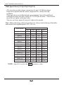
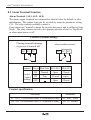
Multi-Speed Select [CF1][CF2][CF3][CF4]
The inverter provides storage parameters for up to 16 different target
frequencies (speeds) that the motor output uses for steady-state run
condition.
These speeds are accessible through programming four of the intelligent
terminals as binary-encoded inputs CF1 to CF4 per the table . These can be
any of the six inputs, and in any order.
You can use fewer inputs if you need eight or less speeds.
Note : When choosing a subset of speeds to use, always start at the top of the table,
and with the least-significant bit: CF1, CF2, etc.
Multi-speed
Speed 0
Speed 1
Speed 2
Speed 3
Speed 4
Speed 5
Speed 6
Speed 7
Speed 8
Speed 9
Speed 10
Speed 11
Speed 12
Speed 13
Speed 14
Speed 15
SW5
OFF
OFF
OFF
OFF
OFF
OFF
OFF
OFF
ON
ON
ON
ON
ON
ON
ON
ON
Control circuit terminal
SW4
SW3
SW2
OFF
OFF
OFF
ON
OFF
OFF
ON
OFF
OFF
ON
ON
OFF
ON
OFF
OFF
ON
ON
OFF
ON
ON
OFF
ON
ON
ON
OFF
OFF
OFF
ON
OFF
OFF
ON
OFF
OFF
ON
ON
OFF
ON
OFF
OFF
ON
ON
OFF
ON
ON
OFF
ON
ON
ON
NOTE : Speed 0 is set by the F 01 parameter value.
plus
N100
INSTRUCTION MANUAL
speed0 speed1speed2 speed3speed4 speed5 speed6 speed7 speed8 speed9 speed10 speed11 speed12 speed13 speed14 speed15
SW2
SW3
SW4
SW5
FW
Multi-speed
Set code
Speed 0
Speed 1
Speed 2
Speed 3
Speed 4
Speed 5
Speed 6
Speed 7
Speed 8
Speed 9
Speed 10
Speed 11
Speed 12
Speed 13
Speed 14
Speed 15
F01
A11
A12
A13
A14
A15
A16
A17
A18
A19
A20
A21
A22
A23
A24
A25
SW5
CF4
OFF
OFF
OFF
OFF
OFF
OFF
OFF
OFF
ON
ON
ON
ON
ON
ON
ON
ON
Control circuit terminal
SW4 SW3 SW2
CF3
CF2
CF1
OFF
OFF
OFF
OFF
OFF
ON
OFF
ON
OFF
OFF
ON
ON
ON
OFF
OFF
ON
OFF
ON
ON
ON
OFF
ON
ON
ON
OFF
OFF
OFF
OFF
OFF
ON
OFF
ON
OFF
OFF
ON
ON
ON
OFF
OFF
ON
OFF
ON
ON
ON
OFF
ON
ON
ON
SW1
FW
ON
ON
ON
ON
ON
ON
ON
ON
ON
ON
ON
ON
ON
ON
ON
ON
Set value
2Hz
5Hz
10Hz
15Hz
20Hz
30Hz
40Hz
50Hz
60Hz
55Hz
45Hz
35Hz
25Hz
15Hz
5Hz
2Hz
plus
N100
INSTRUCTION MANUAL
Standard operator option code
Set the parameter [ C 01
C 06 ] to [ 0 2
Option Terminal
Code Symbol Function Name State
Valid for inputs: C01,C02,C03,C04,C05,C06
Required setting F01, A11 to A25
Notes:
When programming the multi-speed
setting sure to press the Store key each
time and then set the next multi-speed
setting. Note that when the key is not
pressed, no data will be set.
05 ]
Description
Example:
CF4 CF3 CF2 CF1 FW
CM1 6
5
4
3
2
1
P24
SW6 SW5 SW4 SW3 SW2 SW1
When a multi-speed setting more
than 50Hz(60Hz) is to be set, it is
necessary to program the maximum
frequency A04 high enough to allow
that speed.
While using the multi-speed capability, you can monitor the current frequency
with monitor function F 01 during each segment of a multispeed operation.
There are two ways to program the speeds into the registers A 20 to A 25
Programming using the CF switches, Set the speed by following these steps
(1) Turn the Run command off(Stop Mode).
(2) Turn each switch on and set it to Multi-speed n. Display the data section
of F 01 .
(3) Set an optional output frequency by pressing the
and
keys.
(4) Press the STR key once to store the set frequency. When this occurs,
F 01 indicates the output frequency of Multi-speed n.
(5) Press the FUNC key once to confirm that the indication is the same as the set
frequency.
(6) When you repeat operations in (1) to (4), the frequency of Multi-speed can
be set. It can be set also be parameters A 11 to A 25
N100plus INSTRUCTION MANUAL
Jogging Command [JG]
[JG]
terminal
When the terminal [JG] is turned on and
the Run command is issued, the inverter
[FW,RV]
(Run)
outputs the programmed jog frequency
A 27
to the motor. Use a switch between
Motor
time
terminals [CM1] and [P24] to activate
speed
Jog decel type
A 27
the JG frequency.
0:Free-run stop
The frequency for the jogging operation is
1:Deceleration stop
2:DC braking stop
set by parameter A 26 .
Set the value
1 (terminal mode) in A 02 (Run command)
Since jogging does not use an acceleration ramp, we recommend
setting the jogging frequency in A 26 to 5Hz or less to prevent tripping.
The type of deceleration used to end a motor jog is selectable by
programming function A 27 The options are:
0 : Free-run stop (coasting)
1 : Deceleration (normal level) and stop
2 : DC braking and stop
Option Terminal Function Name
Code Symbol
Input
State
Description
Inverter is in Run Mode, output to
ON motor runs at jog parameter
Jogging
JG
6
frequency.
OFF Inverter is in Stop Mode.
Valid for inputs: C01,C02,C03,C04,C05,C06 Example:
Required setting A02, A26, A27
JG
FW
Notes:
CM1 6 5 4 3 2 1 P24
No jogging operation is performed when
the set value of jogging frequency A26 is
smaller than the start frequency B10 or the
value is 0Hz.
Be sure to stop the motor when switching
the function [JG] on or off.
plus
N100
INSTRUCTION MANUAL
Second Control Function [SET]
If you assign the [SET] function to a logic terminal, the inverter will display
the Sxx numbered parameters, allowing you to edit the second motor
parameters. These parameters store an alternate set of motor characteristic
parameters. When the terminal [SET] is turned on, the inverter will use the
second set of parameters to generate the frequency output to the motor.
When changing the state of the [SET] input terminal, first confirm the inverter
is in the Stop Mode, and the motor is not rotating.
When the switch between the set terminals [SET] and [CM1] is on, the
inverter operates per the second set of parameters.
When the terminal is turned off, the output function returns to the original
settings(first set of motor parameters.)
Option Terminal Function Name
Code Symbol
Input
State
Description
Causes the inverter to use the 2nd
of motor parameters for
ON set
generating the frequency output to
motor
7
SET
Set 2nd Motor
Causes the inverter to use the 1st
(main) set of motor parameters
OFF for heating the frequency
output to motor
Valid for inputs: C01,C02,C03,C04,C05,C06 Example:
Required setting (none)
SET
Notes:
If the terminal is turned off while the motor
is running, the inverter continues to generate the frequency output using the 2nd set
of parameters until the motor is stopped.
CM1 6
5
RV FW
4
3
2
1
P24
plus
N100
INSTRUCTION MANUAL
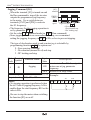
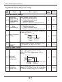
Two-stage Acceleration and Deceleration[2CH]
When terminal [2CH] is turned on, the
inverter changes the rate of acceleration
[FW, RV]
and deceleration from the initial settings
[2CH]
F 02 (acceleration time1) and F 03
(deceleration time1) to use the second
set of acceleration / deceleration values.
Output
When the terminal is turned off, the
frequency
equipment is turned off, the equipment is
returned to the original acceleration and deceleration time
( F 02 acceleration time1 and F 03 deceleration time1). Use A 54
(acceleration time2) and A 55 (deceleration time2) to set the second
stage acceleration and deceleration time.
In the graph shown above, the [2CH] becomes active during the initial
acceleration. This causes the inverter to switch form using acceleration 1
( F 02 ) to acceleration 2 ( A 54 )
Option Terminal Function Name Input
Description
State
Code Symbol
8
Two-stage
2CH Acceleration
and Deceleration
Time
output uses 2nd-stage
ON Frequency
acceleration and deceleration values
Frequency output uses the initial
OFF acceleration 1 and deceleration 1
values
Valid for inputs: C01,C02,C03,C04,C05,C06 Example:
Required setting A54, A55, A56
2CH
Notes:
Function A56 selects the method for
second stage acceleration. It must be
00 to select the input terminal method
in order for the 2CH terminal
assignment to operate.
CM1 6
5
FW
4
3
2
1
P24
plus
N100
INSTRUCTION MANUAL
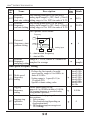
Free-run stop [FRS]
When the terminal [FRS] is turned on, the inverter stops the output and the
motor enters the free-run state (coasting). If terminal [FRS] is turned off, the
output resumes sending power to the motor if the Run command is still active.
The free-run stop feature works with other parameters to provide flexibility in
stopping and starting motor rotation.
In the figure below, parameter B 16 selects whether the inverter resumes
operation form 0Hz (left graph) or the current motor rotation speed (right
graph) when the [FRS] terminal turns off. The application determines which
is the best setting. Parameter B 03 specifies a delay time before resuming
operation from a free-run stop. To disable this feature, use a zero delay time.
[FW,RV]
[FW,RV]
[FRS]
[FRS]
0Hz start
Motor speed
Motor speed
Option Terminal Function Name
Code Symbol
9
FRS
(
b 03
wait time)
Input
State
Description
ON
Causes output to turn off, allowing
motor to free run (coast) to stop
OFF
Output operates normally, so
contorolled deceleration stops
motor
Free-run Stop
Valid for inputs: C01,C02,C03,C04,C05,C06 Example:
Required setting B03, b16, C07 to C12
Notes:
When you want the [FRS] terminal to be
active low(normally closed logic), change
the setting (C07 to C12) which corresponds
to the input (C01 to C06) that is assigned
the [FRS] function
FRS
CM1 6
5
4
3
FW
2
1
P24
plus
N100
INSTRUCTION MANUAL
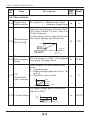
External Trip [EXT]
When the terminal [EXT] is turned on, the inverter enters the trip state, indicates
error code E 12 , and stop the output. This is a general purpose interrupt type
feature, and the meaning of the error depends on what you connect to the
[EXT] terminal. When the switch between the set terminals [EXT] and [CM1]
is turned on, the equipment enters the trip state. Even when the switch to
[EXT] is turned off, the inverter remains in the trip state. You must reset the
inverter or cycle power to clear the error, returning the inverter to the Stop
Mode.
RUN command [FW, RV]
[EXT] terminal
start
Motor revolution speed
[RS] terminal
Alarm output terminal
Option Terminal Function Name
Code Symbol
10
EXT
Input
State
Description
ON
When assigned input transitions
Off to On, inverter latches trip
event and displays E12
OFF
No trip event for On to Off, any
recorded trip events remain in
history until Reset.
External Trip
Valid for inputs: C01,C02,C03,C04,C05,C06 Example:
Required setting (none)
CM1 6
Notes:
If the USP (Unattended Start Protection)
feature is in use, the inverter will not
automatically restart after cancelling the
EXT trip event. In that case, it must
receive enter Run command
(off-to-on transition)
5
EXT
FW
4
3 2
1
P24
plus
N100
INSTRUCTION MANUAL
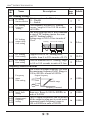
Unattended Start Protection [USP]
If the Run command is already set when power is turned on, the inverter starts
running immediately after power up. The Unattended Start Protection (USP)
function prevents that automatic start up, so that the inverter will not run without outside intervention. To reset an alarm and restart running, turn the Run
commend off or perform a reset operation by the terminal [RS] input or the
keypad Stop/reset key.
In the figure below, the [UPS] feature is enabled. When the inverter power
turns on, the motor does not start, even though the Run command is already
active. Instead, it enters the USP trip state, and displays E 13 error code.
This forces outside intervention to reset the alarm by turning off the Run
command. Then the Run command can turn on again and start the inverter
output.
Inverter power supply
RUN command [FW, RV]
[USP] terminal
Alarm output terminal
Inverter output frequency
Alarm
display
E 13
Alarm
cleared
Run
command
plus
N100
INSTRUCTION MANUAL
Option Terminal Function Name
Code Symbol
11
USP
Input
State
Description
ON
On power up, the inverter will not
resume a Run command (mostly
used in the Us)
OFF
On power up, the inverter will not
resume a Run command that was
active before power loss
Unattended Sart
Protection
Valid for inputs: C01,C02,C03,C04,C05,C06 Example:
Required setting (none)
Notes:
Note that when a USP error occurs and
it is canceled by a reset from a [RS]
terminal input, the inverter restarts
running immediately.
Even when the trip state is canceled by
turning the terminal [RS] on and off after
an under voltage protection E09 occurs,
the USP function will be performed.
When the running command is active
immediately after the power is turned on,
a USP error will occur. When this function
is used, wait for at least three seconds after
the power up to generate a Run command.
CM1 6
5
USP
FW
4
3 2
1
P24
plus
N100
INSTRUCTION MANUAL
Analog Input Current/Voltage Select [AT]
The [AT] terminal selects whether the inverter uses the voltage [O] or current
[OI] input terminals for external frequency control. When the switch between
the terminals [AT] and [CM1] is on, it is possible to set the output frequency
by applying a current input signal at [OI]-[L]. When the terminal is turned off,
the voltage input signal at [O]-[L] is available. Note that you must also set
parameter A 01 = 1 to enable the analog terminal set for controlling the inverter
frequency.
Option Terminal Function Name
Code Symbol
13
AT
Analog Input
Voltage/current
select
Input
State
Description
ON
Terminal OI is enabled for current
input(uses terminal L for power
supply return)
OFF
Terminal O is enabled for voltage
input(uses terminal L for power
supply return)
Valid for inputs: C01,C02,C03,C04,C05,C06
Required setting A01=01
Notes:
If the [AT] option is not assigned to any
intelligent input terminal, then inverter
uses the algebraic sum of both the
voltage and current inputs for the frequency
command(and A01=01)
When using either the analog current and
voltage input terminal, make sure that the
[AT] function is allocated to an intelligent
input terminal.
Be sure to set the frequency source setting
A01=01 to select the analog input terminals.
Example:
AT
CM1 6
5
SFT
4
ON
3
FW
2
1
P24
plus
N100
INSTRUCTION MANUAL
Reset Inverter [RS]
The [RS] terminal causes the inverter to
12 min
execute the reset operation. If the inverter
is in Trip Mode, the reset cancels the Trip
[RS]terminal
state. When the switch between the set
approx.30
terminals [RS] and [CM1] is turned on and Alarm output
off, the inverter executes the reset operation.
The input timing requirement for [RST] needs a 12 ms pulse width or greater.
The alarm output will be cleared within 30 ms after the onset of the Reset
command.
DANGER
After the Reset command is given and the alarm reset occurs, the motor will
restart suddenly if the Run command is already active. Be sure to set the
alarm reset after verifying that the Run command is off to prevent injury to
personnel.
Option Terminal Function Name
Code Symbol
Input
State
Description
The motor output is turned off, the
Trip Mode is cleared(if it exists),
and power up reset is applied
Reset Inverter
14
RS
Normal power-on operation
OFF
Valid for inputs: C01,C02,C03,C04,C05,C06
Example:
Required setting (none)
RS
ON
Notes:
3 2
1 P24
5 4
CM1 6
When the control terminal [RS] input is already
at power up for more than 4 seconds, the display
of the digital operator is E60. However, the
inverter has no error.
To clear the digital operator error, turn off the terminal [RS] input and press stop/ reset butt
on of the operator.
When the [RS] terminal is turned off from on, the Reset command is active.
The stop/reset key of the digital operator is valid only when an alarm occurs.
Only the normally open contact [NO] can be set for a terminal configured with the [RS]
function. The terminal cannot be used in the normally closed contact [NC] state.
Even when power is turned off or on, the function of the terminal is the same as that of the
reset terminal.
The Stop/Reset key on the inverter is only operational for a few seconds after inverter
power up when a hand-held remote operator is connected to the inverter.
If the [RS] terminal is turned on while the motor is running, the motor will be
free running(coasting)
plus
N100
INSTRUCTION MANUAL
Software Lock[SFT]
When the terminal [SFT] is turned on, the data of all the parameters and
functions except the output frequency is locked (prohibited from editing).
When the data is locked, the keypad keys cannot edit inverter parameters.
To edit parameters again, turn off the [SFT] terminal input.
Use parameter B31 to select whether the output frequency is excluded from the
lock state or is locked as well.
Option Terminal Function Name
Code Symbol
15
SFT
Input
State
Description
ON
The keypad and remote programming devices are prevented from
changing parameters
Software Lock
parameters may be edited
OFF The
and stored
Valid for inputs: C01,C02,C03,C04,C05,C06
Required setting B09 (excluded from lock)
Notes:
When the [SFT] terminal is turned on,
only the output frequency can be
changed.
Software lock can be made possible also
for the output frequency by b09
Software lock by the operator is also
possible without [SFT] terminal being
used (b09)
Example:
CM1 6
5
SFT
FW
4
3 2
1
P24
plus
N100
INSTRUCTION MANUAL
8.4 Using intellingent output terminals
(Initial setting is a-contact [NO])
Frequency Arrival Signal [FA1]/[FA2]
Frequency Arrival [FA1] and [FA2] signals indicate when the output frequency
accelerates or decelerates to arrive at a constant frequency. Refer to the figure
below. Frequency Arrival [FA1](upper graph) turns on when the output
frequency gets within 0.5Hz below or 1.5Hz above the target constant
frequency.
The timing is modified by a small 60ms delay. Note the active low nature of
the signal, due to the open collector output.
Frequency Arrival [FA2] (lower graph) uses thresholds for acceleration and
deceleration to provide more timing flexibility than [FA1].
Parameter C21 sets the arrival frequency threshold for acceleration, and
parameter C22 sets the thresholds for deceleration. This signal also is active
low and has a 60ms delay after the frequency thresholds are crossed.
Output
frequency
Hz
F 01
set value 1.5
0.5
F 01
0.5
FA1
signal
ON
60
set value
1.5
ON
60
Output
frequency
Hz
Thresholds
C 21 set value
C 22 set value
0.5
FA2
signal
1.5
ON
60
plus
N100
INSTRUCTION MANUAL
Option Terminal
Code Symbol
Function Name
Input
State
Description
when output to motor is at the
set frequency
when output to motor is off,
OFF or in any acceleration or
deceleration ramp
when output to motor is at or
above the set frequency the
ON holds for, even if in acceleration
or deceleration ramps
when output to motor is off,
during acceleration or decelOFF or
eration before the respective
thresholds are crossed
ON
1
FA1
Frequency arrival
type 1 signal
2
FA2
Frequency arrival
type 2 signal
Valid for inputs: C13, C14, C21, C22
Required setting (none)
Example:
Open collector output
Notes:
At the time of acceleration, an arrival signal at
Fa1/ FA2
a frequency between the set frequency -0.5Hz
to +1.5Hz is turned on.
CM2 12
11
At the time of deceleration, an arrival signal at
a frequency between the set frequency +0.5Hz
to -1.5Hz is turned on.
RY
The delay time of the output signal is 60ms
50 max
(nominal).
DC 27Vmax
plus
N100
INSTRUCTION MANUAL
Run Signal [RUN]
When the [RUN] signal is selected as an intelligent output terminal, the inverter
outputs a signal on that terminal when it is in the Run Mode. The output logic
is active low, and is the open collector type (switch to ground)
Run
command
FW[RV]
Motor
speed
DC braking
Run
signal
Option Terminal
Code Symbol
0
RUN
ON
Function Name
Run signal
ON
Input
State
Description
ON
when inverter is in Run Mode
OFF
when inverter Stop Mode
Valid for inputs: C13, C14
Required setting (none)
Notes:
The inverter outputs the [RUN] signal
whenever the inverter output exceeds the
start frequency . The start frequency is the
initial inverter output frequency when it
turns on.
Example:
Open collector output
RUN
CM2
12
11
RY
50 max
DC 27Vmax
NOTE : The example circuit in the table above drives a relay coil. Note the use
of a diode to prevent the negative-going turn-off spike generated by the coil
from damaging the inverter's output transistor.
plus
N100
INSTRUCTION MANUAL
Overload Advance Notice Signal [OL]
When the output current exceeds a
preset value, the [OL] terminal signal
Current
turns on. The parameter C20 sets the
Power running
C 20
overload threshold. The overload
Regeneration
set value
detection circuit operates during
powered motor operation and during
regenerative braking. The output circuits
use open-collector transistors, and are
OL
signal
active low.
Option Terminal
Code Symbol
Function Name
Input
State
ON
3
OL
Overload advance
notice signal
Description
when output current is more than
the set threshold for the overload
signal
when output current is less than
OFF the set threshold for the overload
signal
Valid for inputs: C13, C14, C20
Required setting C23
Notes:
The default value is 100%. To change the
level from the default, set C20 (overload
level).
The accuracy of this function is the same as
the function of the output current monitor
on the [FM] terminal
Example:
Open collector output
CM2
OL
12
RY
50 max
DC 27Vmax
11
plus
N100
INSTRUCTION MANUAL
Output Deviation for PID Control [OD]
The PID loop error is defined as the
magnitude(absolute value) of the
difference between the Set point
(target value) and the process Variable
(actual value). When the error magnitude
exceeds the press value for C23, the [OD]
terminal signal turns on. Refer to the PID
loop operation.
Option Terminal
Code Symbol
Function Name
Input
State
ON
4
OD
Output deviation
for PID control
Process variable
Current
Setpoint
C 23
set value
OD
signal
Description
when PID error is more than the
set threshold for the deviation
signal
when PID error is less than the
OFF set threshold for the deviation
signal
Valid for inputs: C13, C14, C23
Required setting C23
Example:
Open collector output
Notes:
The default difference value is set to 10%.
To change the value, change parameter
C23 (deviation level).
OD
CM2
12
11
RY
50 max
DC 27Vmax
NOTE : The example circuit in the table above drives a relay coil. Note the use
of a diode to prevent the negative-going turn-off spike generated by the coil
from damaging the inverter's output transistor.
plus
N100
INSTRUCTION MANUAL
Alarm Signal output [AL]
The Inverter alarm signal is active when a fault has occurred and it is in the
Trip Mode. When the fault is cleared the alarm signal becomes inactive.
We must make a distinction between the alarm signal [AL] and the alarm relay
contacts AL0, AL1and AL2. The signal [AL] is a logic function which you
can assign to the open collector output terminals 11, or 12, or the relay outputs.
The most common (and default) use of the relay is for [AL], thus the labeling
of its terminals.
Option Terminal
Code Symbol
5
AL
Function Name
Alarm signal
Input
State
Description
an alarm signal has occurred
ON When
and has not been cleared
When no alarm has occurred since
OFF the last clearing of alarm(s)
Valid for inputs: 11, 12, AL0-AL2
Example: Open collector output
Required setting C13, C14,C15,C16
Notes:
AL
When the alarm output is set to normally
CM2
12
11
closed [NC], a time delay occurs until the
contact is closed when the power is turned
on. Therefore, when the alarm contact outRY
50 max
put is to be used, set a delay of about 2
DC 27Vmax
seconds when the power is turned on.
Terminals 11 and 12 are open collector outputs, so the electric specification of [AL] is
different from the contact output terminals AL0, AL1, AL2.
The logic sequence of terminals 11 and 12 is the same as AL0-AL2.
See the description of AL1, AL2 and AL0.
When the inverter power supply is turned off, the alarm signal output is valid
as long as the external control circuit has power.
The signal output has the delay time(300ms nominal) from the fault alarm
output.
Output terminal 11 is a contact a.
In case of contact b, set up C15.
Output terminal 12 is a contact a.
In case of contact b, set up C16.
plus
N100
INSTRUCTION MANUAL
8.5 Alarm Terminal Function
Alarm Terminal [AL1, AL2- AL0)
The alarm output terminals are connected as shown below by default, or after
initialization. The contact logic can be inverted by using the parameter setting
C16. The relay contacts normally contact a.
Convention uses "normal' to mean the inverter has power and is in Run or Stop
Mode. The relay contacts switch to the opposite position when it is Trip Mode
or when input power is off.
Contact a (Initial setting)
During normal running
or power is turned off
when an alarm occurs
AL0 AL1 AL2
AL0 AL1 AL2
contact Power Run State AL0-AL1 AL0-AL2
ON
Contact a
(initial ON
setting) OFF
Normal
Open
Closed
Trip
Closed
Open
Open
Closed
Contact specification
Maximum
Minimum
AC 250V, 2.5A(Resistor load), 0.2A(Inductive load)
AC 100V, 10mA
DC 30V, 3.0A(Resistor load), 0.7A(Inductive load)
DC 5V, 100mA
plus
N100
INSTRUCTION MANUAL
8.6 Configuring the Inverter of Multiple Motors
Simultaneous Connections
For some applications, you may need to connect two motors (wired in
parallel) to a single inverter's output. For example, this is common in
conveyors applications where two separate conveyors need to have approximately the same speed. The use of two motors may be less expensive than
making the mechanical link for one motor to drive multiple conveyors.
Inverter Configuration for Two Motor Types
Function Name
Multi-speed frequency setting
Acceleration time setting (Acceleration 1)
Deceleration time setting (Deceleration 1)
Second acceleration time setting (Acceleration 2)
Second acceleration time setting (Deceleration 2)
Second method to use 2nd acceleration/deceleration
Acc1 to Acc2 frequency transition point
Dcc1 to Dcc2 frequency transition point
Acceleration patten setting
Dece1eration patten setting
Leve1 of electronic thermal setting
Select electronic thermal characteristic
Torques boost mode selection
Manual torque boost setting
Manual torque boost frequency adjustment
V/F characteristic curve selection
Base frequency setting
Maximum frequency setting
Select motor constant
Motor capacity setting
Motor poles setting
Motor Rated Current
Motor constant R1 setting (Standard, Auto tuning)
Motor constant R2 setting (Standard, Auto tuning)
Leakage inductance (Standard, Auto tuning)
Leakage factor (Standard, Auto tuning)
No load current(Standard, Auto tuning)
Parameter Codes
1st motor 2nd motor
S01
F01
S02
F02
S03
F03
S10
A54
S11
A55
S14
A56
S15
A57
S16
A58
S12
A59
S13
A60
S17
B04
S18
B05
S06
A28
S07
A29
S08
A30
S09
A31
S04
A03
S05
A04
S19
H02
S20
H03
S21
H04
S22
H05
H06/H11 S23/S28
H07/H12 S24/S29
H08/H13 S25/S30
H09/H14 S26/S31
H10/H15 S27/S32
plus
N100
INSTRUCTION MANUAL
8.7 Sensorless Vector Control
Function description
plus
plus
The N100 inverter has a built-in auto-tuning algorithm. The N100
inverter can be possible to do high-starting torque and high-precision operation.
Also, the settings have a second set of parameters for a second motor.
The required torque characteristic or speed control characteristic may not be
maintained in case that the inverter capacity is move than twice the capacity of
the motor in use .
Function setting method
Select the parameter A31 to 2 ( sensorless vector control).
Parameter H03 and H04 select motor capacity and poles (4-poles).
Parameter H02 selects which data(standard data, auto-tuning data) of motor
constants you want the inverter to use.
plus
N100
INSTRUCTION MANUAL
8.8 Auto-tuning
Function description
The auto-tuning procedure automatically sets the motor parameter related to
sensorless vector control. Since sensorless vector control needs motor
parameter, the standard motor parameters have been set at the factory.
Therefore, when an inverter exclusive-use motor is used or when a motor of
any other manufacture is drive, the motor parameter is detected by auto-tuning
because the parameters are not matched.
Function setting
Follow the steps below to auto-tune the inverter, finally set the parameter H01.
F02, F03 setting : Set the time the range that over-current or over-voltage trip
event not occurs.
Set the same as setting F02.
H03 setting : Set the motor rating.
0 4 : 004LF 037LF
5 9 : 004HF 037HF
H04 setting : set the motor poles
A01 setting : set the frequency command source to 0 (potentiometer)
A03 setting : set the base frequency(60Hz)
F01 setting : set the operation frequency except 0hz (by the potentiometer)
A53 setting : select output voltage for motor.
A33 setting : set DC braking setting to 0(disable).
H01 setting : select the auto-tuning mode (1).
After setting above parameters, press the RUN key on the standard operator.
{
}
plus
N100
INSTRUCTION MANUAL
Auto-tuning method
Motor connection
Auto-tuning mode
selection H01=1
Run command ON
Motor parameter setting
Parameter setting
completed, stop
AC excitation (no rotation)
DC excitation (no rotation)
Motor accelerates to 80% of
base frequency, the stops.
End display
auto-tuning process completed:
auto-tuning process failed
:
Note) The motor parameter of N100plus is standard data of HYUNDAI
standard 4-poles motor. At the sensorless vector control when using
different poles motor, operates by using auto-tuning data as a motor
parameter.
plus
N100
INSTRUCTION MANUAL
Setting Method
(1) Digital panel
No
Name
Setting range
Description
H01
auto-tuning
mode selection
0/1
0 : auto-tuning OFF
1 : auto-tuning ON
H02
motor data
setting
0/1
0 : standard data
1 : auto-tuning data
H03
motor capacity
0 9
0 4 : 004LF 037LF
5 9 : 004HF 037HF
H04
motor poles
2/4/6/8
Unit : pole
H06/H11
motor resistor
R1
0.001-30.00
Unit :
H07/H12
motor resistor
R2
0.001-20.00
Unit :
H08/H13
Motor
inductance
0.01-999.9
Unit : mH
H09/H14
Transient
inductance
0.01-100.0
Unit : mH
H10/H15
No-load
current
0.1-100.0
Unit : A
The data of H11 to H15 is auto-turning data.
plus
N100
INSTRUCTION MANUAL
Remark
1. If satisfactory performance through auto-tuning cannot be fully obtained,
please adjust the motor constants for the observed symptoms according to the
table below.
Operation
status
Symptom
Adjustment
Parameter
When low frequency Slowly increase the motor constant H06/H11/
(a few Hz) torque is R1 in relation to auto-tuning data S23/S28
insufficient.
within 1 to 1.2 times R1.
Slowly increase the motor constant H07/H12/
When the speed
deviation is negative. R2 in relation to auto-tuning data S24/S29
within 1 to 1.2 times R2.
Powered
running
(status with a
Slowly decrease the motor constant H07/H12/
accelerating When the speed
deviation is positive R2 in relation to auto-tuning data S24/S29
torque)
within 0.8 to 1 times R2.
When over current Slowly increase the motor constant H10/H15/
prote ction is operated IO in relation to auto-tuning data S27/S32
at injection of load within 1 to 1.2 times IO.
Slowly increase the motor constant H06/H11/
R1 in relation to auto-tuning data S23/S28
Regeneration
within
1 to 1.2 times R1.
(status with a When low frequency
Hz) torque Slowly increase the motor constant H10/H15/
decelerating (aisfew
insufficient.
IO in relation to auto-tuning data S27/S23
torque)
within 1 to 1.2 times IO.
Decrease the carrier frequency.
b11
2. If the inverter capacity is more than twice the capacity of the motor in use,
the inverter may not achieve its full performance specifications.
3. Running multiple motor under sensorless vector control is not available.
4. When DC braking is enabled, the motor constant will not be accurately set.
Therefore, disable DC braking before starting the auto-tuning procedure.
5. The motor will rotate up to 80% of base frequency : make sure that acceleration or deceleration is not operated. If then, decrease the manual torque
boost setting value.
6. Be sure if motor is in standstill before you carry out an auto-tuning.
Auto-tuning data carried out when motor is still running may be not correct.
7. If the auto-tuning procedure is interrupted by the stop command, the autotuning constants may be stored in the inverter. It will be necessary to store
the inverters factory defaults setting.
plus
N100
INSTRUCTION MANUAL
9. Operating the inverter
9.1 Identifying the parts
STOP/RESET key
RUN LED
on when the inverter This key is use for stopping the motor or resetting
outputs the PWM
errors. (When either operator or terminal is selected,
voltage and operating this key works. If the extension function b 15 is used,
command is ready
this function is void)
PRG LED
POWER LED
This LED is on when the
On when the control
powerinput to inverter
inverter is ready for
is on
parameter editing.
Hz/A LED
Display part (LED display)
Display units Hertz/Ampere
This part display frequency,
motor current, motor
LEDs.
rotation speed, alarm history,
Potentiometer
and setting value.
set the inverter output
RUN key
frequency.(be operated
Press this key to run the
only when the ramp is
motor. The Run enable
ON)
LED must be terminal
operation
UP/ DOWN key STORE KEY
FUNCTION key
This key is used to Press the store key to write the
This key is used for
data and setting value to the
change data and
changing parameter
increase of decrease memory
and command
the frequency.
0.0
9.2 Operation procedure
(Example that the frequency is set from potentiometer to the standard operator and the
equipment starts running)
Display after
power is
turned on FUNC
press the key
once
01
press the key
once FUNC
A --
FUNC
press the key
four times
chage the frequency
command by key
STR store the
operation from the
set the frequency
data
potentiometer
to 60Hz
RUN
060.0
press the key OperMotor
ation Operation
start
0.0
A 01
FUNC
F 01
A--
press the key press the key
once
four times
F 01
01 FUNC 60.0
press the key
9 times
Hz
press the key
once
0
press the key twice
STR store the data
A 01
FUNC
display transition
frequency monitor
plus
N100
INSTRUCTION MANUAL
9.3 Key Description
[FUNCTION key]
58.1
F
2
58.0
or
F
This key allows the selection of commands
and memorises parameters. When the key is
pressed once in the state of, the extension
function code selection state is set.
2
57.9
[UP/DOWN key]
The key are used to select the command and
change the data
0 1 output frequency monitor
0 2 output current monitor
1 4 trip history 1 monitor
0 3 output voltage monitor
1 5 trip history 2 monitor
0 4 rotation direction monitor
1 6 trip history 3 monitor
control feedback
0 5 PID
value monitor
0 6 input terminal status
1 7 trip count
F 0 1 output frequency setting
monitor
0 7 output terminal status
monitor
0 8 output frequency scale
factor monitor
0 9 power comsumption
monitor
operating
time
10
accumulation monitor
1 1 real operating time monitor
A --
basis setting functions
b --
fine tuning functions
1 2 DC link votage monitor
C--
terminal setting functions
1 3 trip monitor
S --
seceond motor setting
functions
seceond motor setting
functions
F 0 2 acceleration time 1 setting
F 0 3 deceleration time 1 setting
F 0 4 rotation direction setting
H --
[RUN key]
This key starts the run.
The set value of F 0 4 determines a forward run or a reverse run.
[STOP/RESET key]
This key stops the run
When a trip occurs, this key becomes the reset key.
plus
N100
INSTRUCTION MANUAL
9.4 Expanded function mode navigational map
Using the /
key to enter the expanded function mode, select expanded
function command NO. in A - - b - - C - - S - - and H - - mode.
Expanded function
setting
A --
expanded function command NO.
A 01
A 02
expanded function data
A 65
0
40
store data and return to the expanded
command (setting data is disabled)
do not store data and return to the expanded
command (setting data is disabled)
Display description:
When the inverter is turned on, the output frequency monitor display appears.
plus
N100
INSTRUCTION MANUAL
Function List
Parameter Monitoring Functions
Funccode
Name
Description
Output frequency
monitor
Real-time display of output frequency to
motor, from 0.00 to 400.0 Hz, "Hz" LED ON
Real-time display of output current to motor,
d02 Output current monitor from 0.0 to 99.9A, "A" LED ON.
d01
d03 Output voltage monitor Real-time display of output voltage to motor
d04
Rotation direction
monitor
d05 PID feedback monitor
d06 Intelligent input terminal
status
Three different indications:
"F"..... Forward Run
" "... Stop
"r"...... Reverse Run
Displays the scaled PID process variable
(feedback) value (A50 is scale factor)
Displays the state of the intelligent input
terminals:
ON
6 5 4 3 2 1
OFF
Terminal numbers
Displays the state of the intelligent output
terminals:
d07 Intelligent output
terminal status
ON
OFF
AL 12 11
Terminal numbers
Displays the output frequency scaled by the
Scaled
output
frequency
d08
constant in b14.
monitor
Scale factor(b14) x freguency data
plus
N100
INSTRUCTION MANUAL
Funccode
Description
Name
Power consumption
monitor
Operating time
d10 accumulation
monitor(hour)
d09
Displays the power consumption at inverter
starting (W)
Inverter operating accumulation time(0 9999)
Real operating time
d11 monitor (minute)
Inverter real operating time (0 59)
d12 DC link voltage
Displays the inverter DC link voltage(V)
d13 Trip event monitor
Displays the current trip event
Display method
Alarm reason
press the UP key
Output frequency at alarm event
press the UP/DOWN key
Output current at alarm event
press the UP/DOWN key
DC link voltage at alarm event
press the FUNC key
"d13" display
No trip event
d14 Trip history 1 monitor
Displays the previous first trip event
d15 Trip history 2 monitor
Displays the previous secound trip event
d16 Trip history 3 monitor
Displays the previous third trip event
d17 Trip count
Displays the trip accumulation count
plus
N100
INSTRUCTION MANUAL
Basic Function Mode
Funccode
F01
F02
Name
Output
frequency
setting
Acceleration
time1 setting
Deceleration
F03
time 1 setting
Description
Standard default target frequency that
determines constant motor that determines constant motor speed. setting range
is 0.00 to 400.0Hz
(1) frequency setting from UP/DOWN
key of digital operator.
(2) Multi-step speed
By combining frequency reference
and intelligent input terminal ON/
OFF, up to 16 step of speed can be set.
(3) Remote operator (NOP), control
terminal input (O-L, OI-L).
Frequency reference by the local
potentiometer can be monitored.
Standard default acceleration,
setting range is 0.1 to 3000sec.
0.1 999.9 ----- by 0.1sec
minimum
setting range 1000 3000 ----- by 1sec
Standard default deceleration, 2nd motor.
0.1 999.9 ----- by 0.1sec
minimum
setting range 1000 3000 ----- by 1sec
Runtime Defaults
Edit
volume
setting
value
10.0sec
10.0sec
Rotation dire- Two options: select codes:
0
F04 ction setting
0... Forward run
1... Reverse run
Extended fun- Basic setting functions
A-- ction of A group setting range : A01 A65
setting
Extended func- Fine tuning functions
b-- tion of b group Setting range :b01 b17
setting
Extended func- Terminal setting functions
C-- tion of C group Setting range :C01 C23
setting
Extended func- Seond motor setting functions
S-- tion of S group Setting range :S01 S32
setting
Extended func- Sensorless vector setting functions
H-- tion of H group
Setting range :H01 H15
setting
Note) If you set the carrier frequency less than 2kHz, acceleration / deceleration
time delays approximately 500msec.
plus
N100
INSTRUCTION MANUAL
Expanded Function Mode of A Group
Funccode
Runtime Defaults
Edit
Description
Name
Basic parameter settings
Frequency
Four options: select codes:
commanding 0.... Keypad potentiometer
1.... Control terminal input
A01 (Multi-speed
commanding 2.... Standard operator
method)
3.... Remote operator(communication)
Four options: select codes:
Run
0.... Standard operator
A02 commanding 1.... Control terminal input
2.... Remote operator(communication)
Settable from 0 to maximum frequency
in units of 0.01Hz
V
(A04)
Base frequency
100%
A03 setting
0
0
0
60.00Hz
Base
Maximum
Frequency Frequency
(A03)
Maximum
Settable from the base frequency [A03]
A04 frequency
up to 400Hz in units of 0.1 Hz.
setting
Analog Input Settings
60.00Hz
Start frequency provided when analog
input is 0V (4mA) can be set in
units of 0.01Hz setting range is 0 to
400 Hz
Frequency
External
A05 frequency
setting start
A05
OV A07
4mA
External
A06 frequency
setting end
0.00Hz
A06
A08 10V
20mA
Analog Input
End frequency provided when analog
input is 10V(20mA) can be set in units
of 0.01Hz. setting range is 0 to 400Hz
0.00Hz
plus
N100
Funccode
INSTRUCTION MANUAL
Description
Name
External
The starting point(offset) for the active
analog input range(0 10V, 4mA 20mA)
A07 frequency
start rate setting setting range is 0 to 100% in units of 0.1%
The ending point(offset) for the active
External
analog input range(0 10V, 4mA 20mA)
A08 frequency
end rate setting setting range is 0 to 100% in units of 0.1%
Two options: select codes:
Runtime Defaults
Edit
0.0%
100.0%
Frequency
A06
External
A09 frequency start
pattern setting
A09=0
A05
0
A09=1
4V
4mA A07
10V
A08 20mA
Analog input
0.... start at start frequency
1.... start at 0Hz
External
Range n = 1 to 8, where n = number of
A10 frequency
sampling setting samples for average
4
Samples
Multi-speed Frequncy Setting
A11 Multi-speed
frequency
A25 setting
Jogging
A26 frequency
setting
Jogging stop
A27 operation
selection
Defines the first speed of a multispeed profile, range is 0 to 400Hz in
units of 0.01Hz.
Setting range is 1-speed(A11) to
15-speed(A25).
Speed0:volume setting value
Defines limited speed for jog,
range is 0.5 to 10.00Hz in units of 0.01Hz.
The jogging frequency is provided safety
during manual operation.
Define how end of jog stops the motor:
three options:
0.... Free-run stop
1.... Deceleration stop(depending on
deceleration time)
2.... DC braking stop(necessarg to set
DC braking)
speed1:5Hz
speed2:10Hz
speed3:15Hz
speed4:20Hz
speed5:30Hz
speed6:40Hz
speed7:50Hz
speed8:60Hz
etc. 0Hz
0.50Hz
0
plus
N100
INSTRUCTION MANUAL
Funccode
Runtime Defaults
Edit
Description
Name
V/F Characteristics
A28
Torque boost Two options: 0.... Manual torque boost
1.... Automatic torque boost
mode selection
Manual torque
A29 boost setting
0
Can boost starting torque between 0 and
100% above normal V/F curve, from 0 to
1/2 base frequency
Be aware that excessive torgue boost can
cause motor damage and inverter trip.
V
5.0%
100%
A
A29=5.0
frequency
0
A30=10.0%
6.0Hz
0%
30.0Hz
base frequency
=60.0Hz
100% : A30
Manual torque Sets the frequency of the V/F breakpoint
A30 boost frequency
A in graph for torque boost
setting
Two available V/F curves: three select
codes:
0... Constant torque
1... Reduced torque(reduction of the 1.7th
power)
V/F
2...
Sensorless
vector control
A31
characteristic
V
100%
curve selection
Constant
torque
0
10.0%
0
Reduced
torque
frequency
Sets output voltage gain of the inverter
from 20 to 100%
A32 V/F gain setting
V
100%
100.0%
A32
20%
0
frequency
plus
N100
INSTRUCTION MANUAL
Funccode
Runtime Defaults
Edit
Description
Name
DC Braking Settings
A33
DC braking
function selection
A34
DC braking
frequency
setting
A35
DC braking
output delay
time setting
Sets two options for DC braking
0.... Disable
1.... Enable
The frequency at which DC braking
occurs, range is 0.0 to 10.0 Hz in units
of 0.01Hz
The delay from the end of Run command
to start of DC braking (motor free runs
until DC braking begins).
Setting range is 0.0 to 5.0sec in units of
0.1set.
Running
DC braking
Free run
+
0
0.50Hz
0.0sec
0
time
-
DC braking
force setting
A 35
A 37
Applied level of DC braking force,
settable from 0 to 50% in units of 0.1%
10.0%
Sets the duration for DC braking, range
is 0.0 to 10.0 seconds in units of 0.1sec.
Frequency-related Functions
Sets a limit on output frequency less than
the maximum frequency(A04). Range is
0.00 to 400.0Hz in units of 0.01Hz.
0.0sec
A36
A37
DC braking
time setting
A38
Frequency
upper
limit setting
Output frequency
A38 Upper
limit
Lower
A39 limit
A39
Frequency
lower limit
setting
A40
A42
A44
Jump(center)
frequency
setting
0.00Hz
Settable range
Frequency command
Sets a limit on output frequency greater
than zero. Range is 0.00 to 400.0Hz in
units of 0.01Hz
Up to 3 output frequencies can be defined
for the output to jump past to avoid motor
resonances(center frequency) range is
0.00 to 400.0Hz in units of 0.01Hz.
0.00Hz
0.00Hz
plus
N100
INSTRUCTION MANUAL
Funccode
Name
Description
Defines the distance from the center
Jump(hysteresis) frequency at which the jump around
frequency width occurs. Range is 0.00 to 10.00Hz in
A41 setting
units of 0.01Hz
A43
A40
A45
A41
Runtime Defaults
Edit
0.00Hz
PID Control(Note1)
A46 PID Function
selection
PID P
A47 (proportional)
gain setting
PID I (integral)
A48 gain setting
PID D(derivaA49 tive) gain setting
scale factor
A50 PID
setting
A51 Feed-back
method setting
Enables PID function, two option codes:
0.... PID control disable
1.... PID control enable
0
Proportional gain has a range of 0.1
to 100 in units of 0.1.
10.0%
Integral time constant has a range of
0.0 to 100.0 seconds in units of 0.1
Derivative gain has a range of 0.0 to
100 .0 seconds in units of 0.1
PID scale factor (multiplier),
range of 0.1 to 1000 in units of 0.1
10.0sec
Selects source of PID, option codes:
0.... "OI" terminal(current in put)
1.... "O" terminal(voltage in put)
0.0sec
100
0
Automatic Voltage Regulation (AVR) Function
A52
AVR function
selection
Automatic (output) voltage regulation,
selects from three type of AVR functions, three option codes:
0... Constant ON
1... Constant OFF
2... OFF during deceleration
200V class inverter settings:
.... 200/220/230/240
400V class inverter settings:
Motor input
.... 380/400/415/440/460
A53 voltage setting
The AVR feature keeps the inverter
output waveform at a relatively constant
amplitude during power input fluctuations
0
220/
380V
plus
N100
INSTRUCTION MANUAL
Funccode
Name
Runtime Defaults
Edit
Description
Second Acceleration and Deceleration Functions
Duration of 2nd segment of acceleration,
is 0.1 to 3000 sec.
Second accelera- range
Second
acceleration can be set by the
A54 tion time setting
[2CH] terminal input or frequeny
transition setting
Duration of 2nd segment of deceleration,
motor, range is 0.1 to 3000 sec.
Second decelera- Second
acceleration can be set by the
A55 tion time setting
[2CH] terminal input or frequeny
transition setting
A56
Two stage
acce1/dece1
switching
method
selection
10.0sec
10.0sec
Two options for switching from 1st to 2nd
accel/decel:
0.... 2CH input from terminal
1.... transition frequency
0
frequency acc1 acc2
2CH
time
A57 frequency
Output frequency at which Accel 1
switches to Acce1 2, range is 0.00 to
transition point 400.0Hz in units of 0.01Hz.
0.00Hz
Decl to Dec2
Output frequency at which Decel 1
A58 frequency
switches to Dece1 2, range is 0.00 to
transition point 400.0Hz in units of 0.01Hz.
0.00Hz
Acc1 to Acc2
A59 Acceleration
curve selection
Set the characteristic curve of Acc1 and
Acc2, two options:
0... linear, 1... S-curve, 2... U-curve
0
Target freq.
Linear
Deceleration
A60 curve setting
U-curve
S-curve
Set the characteristic curve of dec1
and dec2, two options:
0... linear, 1... S-curve, 2... U-curve
0
plus
N100
INSTRUCTION MANUAL
Funccode
Name
Description
Runtime Defaults
Edit
A61
Input voltage Set the voltage offset for external analog
offset setting signal input input signal adjustment
0.0
A62
Input voltage Set the voltage gain for external analog
Gain setting signal input signal adjustment
100.0
A63
Input current
offset setting
Set the current offset for external analog
signal input signal adjustment
0
A64
Input current
Gain setting
Set the current gain for external analog
signal input signal adjustment
100.0
Set the input power supply for external
External voltage
voltage input frequency
A65 input frequency
0:5V input
selection
1:10V input
0
plus
N100
INSTRUCTION MANUAL
Note 1) PID feedback control
The PID(Proportional, Integral, Differential) control functions can apply to
controlling of fan, the air (water) amount of pump, etc., as well as controlling
of pressure within a fixed value.
[Input method of target value signal and feedback signal]
Set the reference signal according to the frequency setting method or the internal
level.
Set the feedback signal according to the analog voltage input (0 to 10V) or analog
current input (4 to 20mA).
If both input signal (target value and feedback value) set the same terminal,
PID control is not available.
To use analog current [OI-L] for the target value, set the [AT] terminal to ON.
[PID gain adjustment]
If the response is not stabilized in a PID control operation, adjust the gains as
follows according to the symptom of the inverter.
The change of controlled variable is slow even when the target value is changed.
Increase P gain [A47]
The change of controlled variable is fast, but not stable.
Decrease P gain[A47]
It is difficult to make the target value match with the controlled variable.
Decrease I gain [A48]
Both the target value and the controlled variable are not stable.
Increase I gain [A48]
The response is slow even when the P gain is increased.
Increase D gain[A49]
The response is not stabilized due to oscillation even when the P gain is increased.
Decrease D gain[A49]
The figure below is a more detailed diagram of the PID control.
Target value
operator
multi-speed
A50
Feedback value
analog votage input
analog current input
P
A47
+
I
A48 + +
D
A49
A50
Volume
analog votage input
analog current input
+ -
analog iput
setting
A05-A08
F01
A50
monitor
d05
Frequency setting
plus
N100
INSTRUCTION MANUAL
Expanded Function mode of B Group
Funccode
Name
Runtime Defaults
Edit
Description
Restart Mode
b01
Selection of
restart mode
Allowable
instantaneous
b02 power failure
time setting
Reclosing stand
by after
b03 instantaneous
power failure
recovered
Select inverter restart method, four option
codes:
0.... Alarm output after trip, no automatic
restart
1.... Restart at 0Hz
2.... Resume operation after frequency
matching
3.... Resume previous freq. after freq.
matching, then decelerate to stop and
display trip info.
Restart trip is overcurrent, overvoltage
and under voltage.
Overcurrent and over voltage trip restart
up to 3 times, under voltage trip restart
up to 10time.
0
The amount of time a power input under
voltage can occur without tripping the
power failure alarm. Range is 0.3 to 1.0
sec. If under-voltage exists longer than
this time, the inverter trips, even if the
restart mode is selected.
1.0sec
Time delay after under-voltage condition
goes away, before the inverter runs motor
again. Range is 0.3 to 3.0 seconds.
Input power
failure
Motor speed
b02
b03
1.0sec
plus
N100
INSTRUCTION MANUAL
Funccode
Runtime
Edit
Description
Name
Defaults
Electronic Thermal Overload Alarm Setting
Electronic
b04 thermal
level setting
Electronic
b05 thermal
characteristic,
selection
Set a level between 20% and 120% for
the rated inverter current.
setting range- 0.2 (inverter rated
current) 1.2 (inverter rated current).
Select from two curves, option codes:
0....(SUB) reduced torque characteristic
1....(CRT) constant torque characteristic
Constanttorque(CRT)
100
80
output
current 60
Reducedtorque(SUB)
0
120
5 20 60
Outputfrequency(Hz)
100.0%
1
Overload Restriction
Overload
b06 overvoltage
restriction
mode selection
Select overload or overvoltage restriction
mode;
0.... Overload,overvoltage restriction
mode OFF
1.... Overload restriction mode ON
2.... Overvoltage restriction mode ON
3....Overload,overvoltage restriction
mode OFF
Overload
b07 restriction
level setting
Sets the level for overload restriction,
between 20% and 200% of the rated
current of the inverter, setting range- 0.2
( inverter rated current) 2.0 ( inverter
rated current).
Overload
b08 restriction
constant setting
1
125.0%
Set the deceleration rate when inverter
detects overload,
range is 0.1 to 10.0 and
resolution is 0.1
Motor
Current
b07
Output
frequency
b08
1.0sec
plus
N100
INSTRUCTION MANUAL
Funccode
Name
Description
Runtime Defaults
Edit
Software Lock Mode
Prevents parameter changes, in four
options, option codes:
0.... All parameters except b09 are locked
when SFT from terminal is on
b09 Software lock 1.... All parameters except b09 and outmode selection
put frequency F01 are locked when
SFT from terminal is ON
2.... All parameters except b09 are locked
3.... All parameters except b09 and output
frequency F01 setting are locked
Other Function
Start frequency Sets the starting frequency for the inverter
output, range is 0.50 to 10.00Hz in units
b10 adjustment
of 0.01Hz
Carrier frequthe PWM carrier frequency, range
b11 ency setting Sets
is 0.5 to 16.0kHz in units of 0.1kHz.
Select the type of initialization to occur,
Initialization
two option codes:
b12 mode(parameters 0.... Trip history clear
or trip history) 1.... Parameter initialization
Select default parameter values for country on initialization, three options,
Country code option codes:
b13
for initalization 0.... Korea version
1.... Europe version
2.... US version
Frequency scalar Specify a constant to scale the displayed
frequency for [d08] monitor, range is
b14
conversion factor 0.01 to 99.9 in units of 0.01
Select whether the STOP key on the k
STOP key
eypad is enabled, two option codes:
b15 validity during 0.... stop enabled
terminal operation 1.... stop disabled
Select how the inverter resumes operaResume on tion when the free-run stop (FRS) is
cancelled, two options:
b16 FRS cancel- 0... Restart from 0Hz
lation mode 1.... Restart from frequency detected from
real speed of motor
Communication Sets the communication number for
b17
communication, range is 1 to 32
number
0
0.50Hz
5.0kHz
0
0
o
1.00
0
0
1
plus
N100
INSTRUCTION MANUAL
Expanded Function Mode of C Group
Funccode
Name
Description
Runtime Defaults
Edit
Input TerminalFunction
Select function for terminal 1
Intellingent Input
C01 terminal 1 setting
<code> 0: Forward run command(FW)
1: Reverse run command(RV)
2: 1st multi-speed command(CF1)
3: 2nd multi-speed command(CF2)
4: 3rd multi-speed command(CF3)
5: 4th multi-speed command(CF4)
6: Jogging operation command(JG)
7: 2nd function setting command(SET)
8: 2-stage acceleration/deceleration command(2CH)
9: free-run stop command(FRS)
10:external trip(EXT)
11:unattended start protection(USP)
12:software lock function(SFT)
13.analog input current/voltage selection signal(AT)
14:reset(RS)
0
Intellingent Input Select function for terminal 2
C02 terminal 2 setting <code>-see C01 parameter
1
Intellingent Input Select function for terminal 3
C03 terminal 3 setting <code>-see C01 parameter
2
Intellingent Input Select function for terminal 4
C04 terminal 4 setting <code>-see C01 parameter
3
Intellingent Input Select function for terminal 5
C05 terminal 5 setting <code>-see C01 parameter
8
Intellingent Input Select function for terminal 6
C06 terminal 6 setting <code>-see C01 parameter
14
Input Terminal 1 Select logic convention, two option codes:
C07 a/b contact setting 0.... normally open [NO]
1.... normally closed [NC]
(NO/NC)
0
Input Terminal 2 Select logic convention, two option codes:
C08 a/b contact setting 0.... normally open [NO]
1.... normally closed [NC]
(NO/NC)
0
Input Terminal 3 Select logic convention, two option codes:
C09 a/b contact setting 0.... normally open [NO]
1.... normally closed [NC]
(NO/NC)
0
plus
N100
INSTRUCTION MANUAL
Funccode
Name
Description
Input Terminal 4 Select logic convention, two option codes:
C10 a/b contact setting 0.... normally open [NO]
1.... normally closed [NC]
(NO/NC)
Input Terminal 5 Select logic convention, two option codes:
C11 a/b contact setting 0.... normally open [NO]
1.... normally closed [NC]
(NO/NC)
Input Terminal 6 Select logic convention, two option codes:
C12 a/b contact setting 0.... normally open [NO]
1.... normally closed [NC]
(NO/NC)
Output Terminal Function
C13
Intellingent
output
terminal 11
setting
Select function for terminal 11
<code>
0... RUN(Run signal)
1.... FA1(Frequency arrival signal:
command arrival)
2.... FA2(Frequency arrival signal:
setting frequency or more)
3.... OL(Overload advance notice
signal)
4.... OD(Output deviation for PID
control)
5.... AL(Alarm signal)
Intellingent
C14 output terminal Select function for terminal 12, 6
code.
12 setting
Select logic convention, two option
Output Terminal 11 codes:
C15 a/b contact setting 0.... normally open [NO]
1.... normally closed [NC]
Select logic convention, two option
Output Terminal 12 codes:
C16 a/b contact setting 0.... normally open [NO]
1.... normally closed [NC]
Select function for terminal FM,
3 options
Montor
signal
0.... output frequency monitor
C17
selection
1.... output current monitor
2.... output voltage monitor
Runtime Defaults
Edit
0
0
0
1
0
0
0
0
plus
N100
INSTRUCTION MANUAL
Funccode
Description
Name
Runtime Defaults
Edit
Output Terminal state setting
Analog meter
C18 gain adjustment Range is 0(45%) to 250(220%),
resolution is 1
Analog meter
C19 offset adjustment Range is -3.0 to 10.0%
resolution is 0.1
Output Terminal related function
Sets the overload signal level between
50% and 200% resolution is 0.1%.
0.5x(Inverter rated current) 2.0x
Overload
(Inverter rated current)
advance
C20 notice signal Motor current
C20
level setting
Over load
signal output
Sets the frequency arrival setting threshold for the output frequency during
acceleration.
Acceleration Setting range is 0.0 to A04, resolution is
arrival signal 0.01Hz output
C21 frequency
frequency
setting
C21
C22
100.0%
0.0%
100%
0.00Hz
freguency
Arrival signal
Deceleration
arrival signal
C22 frequency
setting
Sets the frequency arrival setting threshold for the output frequency during
deceleration, setting range is 0.00 to
400.0Hz resolution is 0.01Hz
0.00Hz
Sets the allowable PID loop error magnitude. Setting range is 0.0 to 100%,
resolution is 0.01%
Target value Feedback value
PID deviation
C23 level setting
PID contrnl
C23
Deviation
signal
10.0%
plus
N100
INSTRUCTION MANUAL
Expanded function mode of S group
Funccode
Name
2nd control,
Multi-speed
frequency
setting
Description
Runtime Defaults
Edit
Range is 0.0 to 400Hz in units of 0.01Hz
(It is enabled by the frequency demanding in
the standard operator)
0speed:
60.00Hz
2nd control ,
S02 Acceleration
time
Range is 0.1 3,000sec
minimum setting unit
0.1 999.9 ----- by 0.1sec
1000 3000 ----- by1sec
10.0sec
2nd control,
S03 Deceleration
time
Range is 0.1 3,000sec
mininmum setting unit
0.1 999.9 ----- by 0.1sec
1000 3000 ----- by 1sec
10.0sec
S01
S04
S05
2nd control,
Base
frequency
2nd control,
maximum
frequency
Range is 0 to SO5 (second control maximum
frequency) in units of 0.1Hz
Range is S04(second control base frequency)
to 400.00Hz in units of 0.1Hz.
Twoselections,optioncodes:
2nd control,
0---manualtorqueboost
S06 torque boost
mode selection 1---automatictorqueboost
Set the manual torque boost voltage. Adjust
2nd control, the motor torque by boosting the output voltage
S07 manual torque above the normal V/F ratio. Be aware that
boost setting excessive torque boost can cause motor damage
and inverter trip.
2nd control,
manual torque The boost is applied from 0 to 50% the base
S08 boost frequency frequency.
adjustment
set the V/F characteristics V
2nd control,
100%
0 --- constant torque
constant torque
V/f
reduced
S09
characteristic 1 --- reduced torpue
torpue
(the 1.7th power)
curve selection
0
2 --- sensorless vector control
60.00Hz
60.00Hz
0
5.0%
10.0%
0
plus
N100
INSTRUCTION MANUAL
Funccode
Runtime Defaults
Edit
Description
Name
Range is 0.1 to 999.9sec in units of 0.1sec,
1000 3000sec in units of 1 sec. Second
acceleration can be set by the [2CH] terminal
input or frequency transition setting
2nd control, Range is 0.1 to 999.9sec in units of 0.1sec,
S11 deceleration 1000 3000sec in units of 1 sec. Second
time 2 setting acceleration can be set by the [2CH] terminal
input or frequency transition setting
2nd control,
Set the characteristic curve of Acc 1 and
S12 acceleration Acc2, three options.
pattem setting 0:linear, 1:S-curve, 2:U-curve
2nd control,
S10 acceleration
time 2 setting
2nd control, Set the characteristic curve of Dec 1 and
S13 deceleration Dec2, three options.
pattem setting 0:linear, 1:S-curve, 2:U-curve
2nd control,
2-stage
S14 Accel./decel.
transition
method setting
0 --terminal(2CH), 1 -- transition frequency
2nd control,
acceleration
S15 transition
frequency setting
Output frequency at which Acc1 switches to
Acc2, range is 0.0 to 400.0Hz in units of
0.01Hz
2nd control,
deceleration
S16 transition
frequency
setting
2nd control,
electronic
S17 thermal level
setting
Output frequency at which Dcc1 switches to
Dcc2, range is 0.0 to 400.0Hz in units of
0.01Hz
Set a level between 20% to 120% for the rated
inverter current
setting range : 0.2*(inverter ratedcurrent)
1.2*(inverter ratedcurrent)
frequency
Acc1
10.00sec
10.00sec
0
0
Acc2
0
2CH
time
0.00Hz
0.00Hz
100.0%
plus
N100
INSTRUCTION MANUAL
Funccode
S18
S19
Description
Name
2nd control,
Electronic
thermal
characteristic
setting
2nd control
motor
constant
setting
Runtime Defaults
Edit
Considering on the overload, the electronic
thermal protects against the motor from
overheating
0 ---- SUB, 1 ---- CRT
1
0 : standard motor constants
1 : auto tune data
0
S20 2nd control, motor 0
capacity selection
9(0 4 : 004LF
5 9 : 004HF
037LF,
037HF )
-
2nd control, motor
S21 poles selection 2/4/6/8
4
2nd control, motor The setting depend on the motor
S22 rated current
capacity
selection
-
2nd control, motor setting range: 0.001 -30.00
S23 constant R1
-
control, motor setting range: 0.001 -20.00
S24 2nd
constant R2
control, motor setting range: 0.1 -999.9mH
S25 2nd
constant L
-
S26 2nd motor control setting range: 0.01 -100.0mH
leakage factor
-
motor
S27 2nd
constant IO
-
setting range: 0.1 -100.0A
-
plus
N100
INSTRUCTION MANUAL
Funccode
Name
S28 2nd motor
constant R1
auto-tuning data
2nd motor
S29 constant R2
auto-tuning data
2nd motor
S30 constant L
auto-tuning data
2nd motor constant
S31 leakage factor
auto-tuning data
2nd motor
S32 constant IO
auto-tuning data
Description
Runtime Defaults
Edit
setting range 0.001 -30.00
-
setting range 0.001 -20.00
-
setting range 0.1 -999.9mH
-
setting range 0.01 -100.0mH
-
setting range 0.1 -100.0A
-
plus
N100
INSTRUCTION MANUAL
Expanded Function mode of H Group
Funccode
Name
Description
Sensorless Vector Control
Two States for auto-tuning function,
Auto-tuning
option codes:
H01
0.... Auto-tuning OFF
mode selection
1.... Auto-tuning ON
Two selections, option codes:
Motor
data
0.... Use standard motor data
H02
selection
1.... Use auto-tuning data
H03 Motor capacity
Ten selections:
0 4 -- 0.4/0.75/1.5/2.2/3.7kW(220V)
5 9 -- 0.4/0.75/1.5/2.2/3.7kW(440V)
H04 Motor poles setting Four selections: 2/4/6/8
The setting depend on the inverter
H05 Motor rated current capacity
H06 Motor Resistance R1 Range is 0.001 to 30.00 ohm
H07 Motor Resistance R2 Range is 0.001 to 20.00 ohm
H08 Motor Inductance L Range is 0.1 to 999.9 mH
Transien
Range is 0.01 to 100.0 mH
H09 Inductance
H10 Motor constant IO Range is 0.1 to 100.0A
Runtime Defaults
Edit
0
0
specified
by the
capacity
of each
inverter
4poles
-
Auto-tuning data setting range is
0.001 to 30.00 ohms
Auto-tuning data setting range is
0.001 to 20.00 ohms
Auto-tuning data setting range is
0.1 to 999.9mH
-
Auto-tuning data setting range is
0.01 to 100.0 mH
-
Motor constant IO
H15 auto-tuning data Auto-tuning data setting range is
0.1 to 100.0A
-
H11 Motor Resistance
R1
H12 Motor Resistance
R2
H13 Motor Inductance
L
Transien
H14 Inductance
-
plus
N100
INSTRUCTION MANUAL
10. Protective function
The various functions are provided for the protection of the inverter itself, but
they may also protection function when the inverter breaks down.
Error
Cause(s)
Name
Code
When the inverter output current exceeds the rated
Overcurrent
current by more than approximately 200% during
E04
protection
the motor locked or reduced in speed. Protection
circuit activates, halting inverter output.
Overload protection When the inverter output current causes the motor
(Electronic thermal) to overload, the electronic thermal trip in the
E05
Regenerative
inverter cuts off the inverter output.
If regenerative energy from the motor or the main
power supply voltage is high, the protective circuit
Over voltage
E07
activates to cut off the inverter output when the
protection
voltage of DC link exceeds the specification
The inverter output is cut off when communication
Communication
in the inverter has an error to external noise,
E60
error
excessive temperature rise, or other factor
Under-voltage
protection
Output
short-circuit
USP error
EEPROM error
External trip
Ground fault
protection
Temperature trip
When the input voltage receives by the inverter
decreases, the control circuit does not function
normally. When the input voltage is below the specification, the inverter output is cut off.
The inverter output was short-circuited. This condition causes excessive current for the inverter, so
the inverter output is turned off.
The USP error is indicated when the power is
turned on with the inverter in RUN state. (Enabled
when the USP function selected)
The inverter output is cut off when EEPROM in
the inverter has an error due to external noise, excessive temperature rise, or other factor
E09
E34
E13
E08
When the external equipment or unit has an error,
the inverter receives the corresponding signal and E12
cuts off the output.
Ground fault is detected between the inverter output section and the motor when the power is turned E14
on, to protect the inverter.
When the temperature in the main circuit increases
due to cooling fan stop, the inverter output is cut
E21
off.(only for the model type with cooling fan)
plus
N100
INSTRUCTION MANUAL
Other display
Contents
Display
It is displayed when initialization of data is processing
(It is not displayed when initialization of history is
processing.)
It is displayed when Copy function is operated by the remote
operator.
There is no data available
(Trip history, PID feedback data)
The auto-tuning operation terminates normally.
copy
plus
N100
INSTRUCTION MANUAL
11. Troubleshooting Tips
Symptom/condition
Probable Cause
Countermeasure
Is the frequency command
source A01 parameter setting
correct?
Is the Run command source
A02 parameter setting
correct?
Make sure the parameter
A01setting correct?
Make sure the parameter
A02setting correct?
Is power being supplied to
terminals R, S and T ? If
so, the power lamp should
be on.
Check terminals R, S and
T then U, V, and W
Turn on the power supply
or check fuses.
The The inverter
motor outputs U,V Is there an error code
will and W are
E
displayed?
not run. not supplying
voltage.
Press the Func key and
determine the error type.
Then clear the error(Reset).
Are the signals to the intelligent input terminals correct?
Is the Run Command active?
Is the[FW] terminal (or [RV]
connected to CM1(via switch,
etc.)
Verify the terminal functions
for C01-C06 are correct.
Turn on Run Command
Supply 24V to [FW] or [RV]
terminal, if configured.
(Terminal mode selection)
Has the frequency setting
for F01 been set greater than
zero?
Are the control circuit terminals H, O, and L connected
to the potentiometer?
Set the parameter for F01
to a safe, non-zero value.
If the potentiometer is the
frequency setting surce,
verify voltage at"O" 0V
Is the RS(reset) function
or FRS(free-run stop)
function on?
Turn off the command(s)
Inverter
outputs U,V, Is the motor load too heavy? Reduce load, and test the
motor independently.
W are supply- Is the motor locked?
ing voltage.
plus
N100
INSTRUCTION MANUAL
Symptom/condition
The direction of the
motor is reversed
Probable Cause
Countermeasure
Are the connections of
output terminal U, V, and
W correct?
Is the phase sequence of
the motor forward or reverse
with respect to U, V, and W?
Make connections according
to the phase sequence of the
motor. In general:
FWD=U-V-W, and
REV=U-W-V.
Are the control terminals
Use terminal [FW] for [RV]
[FW] and [RV]wired
is reverse.
correctly?
Is parameter F04 properly Set motor direction in F04.
set?
If using the analog input, is Check the wiring
the current or voltage at"O" Check the potentiometer or
The motor speed will or"OI"?
signal generating device.
not reach the target
frequency
Reduce the load.
(desired speed)
Heavy loads activate the
Is the load too heavy?
overload restriction feature
(reduces output as needed)
the motor capacity
Is the load fluctuation too Increase
(both inverter and motor)
great?
Fix power supply problem.
Is the supply voltage
Change the output frequency
The rotation is unstable unstable?
or use the jump
Is the problem occurring at slightly,
frequency setting to skip the
a particular frequency?
problem frequency.
Is the maximum frequency
The RPM of the motor setting
A04 correct?
does not match the
Does the monitor function
inverter output freque- d01
display the expected
ncy setting
output frequency?
Verify the V/F settings
match motor specifications
Make sure all scaling is
properly set
plus
N100
INSTRUCTION MANUAL
Symptom/condition
Probable Cause
Countermeasure
Was power turned off after Edit the data and press the
a parameter edit but before store key once
pressing the store key?
Inverter
data is No downloads
not
have occurred.
Edits to data are permanently Wait six seconds or more
correct
stored at power down. Was before turning power off
the time from power off to after editing data.
power on less than six
seconds?
The frequency
setting will not
change.
Run/Stop
does not
operate.
Was the standard operator Make sure the setting mode
mode and terminal mode of [A01], [A02] is changed
changed correctly?
A parameter will
not change
Is the inverter in run mode? Put inverter in stop mode
True for
after an
some parameters cannot be (press the stop/reset key)
edit (reve- certain
Then edit the parameter.
rts to old parameters edited during run mode
setting)
If you're using the[SET]
intelligent input selection
True for all [b09] is the [SFT]
parameters Is switch 4(located on the
back of the remote operator
copy unit) on?
Change the state of the SFT
input, and check the b09
parameter (b09=0)
Turn the switch off
Precautions for data setting
When changing any set data and pressing STR key to store the data, keep the
equipment un-operated for 6 seconds or more after the selected method is
executed. When any key is pressed, or the reset operation is performed, or the
power is turned off within 6 seconds, correct data may not be set.
plus
N100
INSTRUCTION MANUAL
12. Maintenance and Inspection
Please read following safety messages before troubleshooting or performing
maintenance on the inverter and motor system.
DANGER
Wait at least five(5) minutes after turning off the input power supply before
performing maintenance of an inspection. Otherwise, there is the danger of
electric shock.
Make sure that only qualified personnel will perform maintenance, inspection, and part replacement. (Before starting to work, remove any metallic
objects from your person(wristwatch, bracelet, etc.)) Be sure to use tools with
insulated handles. Otherwise, there is a danger of electric shock and/or injury
to personnel.
12.1 General Precautions and Notes
Always keep the unit clean so that dust of other foreign matter does not
enter the inverter.
Take special care in regard to breaking wires of making connection
mistakes.
Firmly connect terminals and connectors.
Keep electronic equipment away from moisture and oil. Dust, steel filings
and other foreign matter can damage insulation, causing unexpected accidents, so take special care.
When removing connectors, never pull the wires(wires for the cooling fan
and logic P.C. board.) Otherwise, there is danger of fire due to wire breakage and/or injury to personnel.
plus
N100
INSTRUCTION MANUAL
12.2 Inspection Items
This chapter provides instructions or checklists for these inspection items:
Daily inspection
Periodic inspection(approximately once a year)
Insulation resistance test(approximately once two years)
Conduct the insulation resistance test by short circuiting the terminals as
shown below.
R
S
T
P
RB U
V
W
Megar
Never test the withstand voltage on the inverter. The inverter has a surge
protector between the main circuit terminals and the chassis ground.
Spare parts
We recommend that you stock spare parts to reduce down time, which include:
Part description
Cooling fan
Case
Symbol
FAN
Quanity
Used Spare
1
1
1
1
Note
015SF
015LF 037LF
007HF 037HF
Front case
Case
Bottom cover
plus
N100
INSTRUCTION MANUAL
Monthly and Yearly Inspection Chart
Overall
Inspection
Inspection
Criteria
Item Inspected Check for... Cyelc
Method
MonthYear
Extreme
Thermometer, Ambient temperature
Ambient
between -10 to 40 ,
temperatures
hygrometer
environment & humidity
non-condensing
Abnormal
environment for
Major devices vibration
Visual and aural Stable
electronic
controls
noise
Main circuit
Power supply Voltage
insulation
tolerance
Ground
Insulation
Adequate
resistance
Mounting
No loose
screws
Components Overheating
Housing
Dirt, dust
Terminal block Secure
connections
Smoothing Leaking
capacitor
swelling
Digital volt meter,
measure between
inverter terminals
R, S, T
Digital volt meter,
GND to terminals
M3: 0.5 0.6Nm
M5: 1.5. 2.0Nm
Thermal trip events No trip events
Vacuum dust and dirt
Visual
No abnormalities
Visual
Visual
No abnormalities
Single click when
switching On or Off
Use Ohm meter to check
braking resistors
Chattering
Aural
Resistors
Cracks or
discoloring
Visual
Cooling fan
Noise
Power down,
Rotation must be smooth
manually rotate
Vacuum to clean
Dust
Control
circuit
Display
No odor,
discoloring
corrosion
Capacitor No leaks or
deformation
Legibility
LEDs
500V class Megohm
meter
Torque wrench M4: 0.98 1.3Nm
Relay(s)
Overall
200V class:
200 to 230V 50/60Hz
400V class:
380 to 460V 50/60Hz
Visual
No abnormalities
Visual
Undistorted appearance
Visual
All LED segments work
Note1: The life of a capacitor is affected by the ambient temperature,
Note2: The inverter must be cleaned periodically. If dust accumulates on the fan
and heat sink, it can cause overheating of the inverter.
plus
N100
INSTRUCTION MANUAL
12.3 General Inverter Electrical Measurements
The following table specifies how to measure key system electrical parameters. The diagrams on the next page show inverter-motor systems the location of measurement points for these parameters.
Parameter
Circuit location Measuring instrument
of measurement
Supply voltage R-S, S-T, T-R
E1
(ER) (ES) (ET)
Supply current R S T Current
(IR) (IS) (IT)
I1
Notes
Moving-coil type Fundamental
voltmeter or recti- wave effective
fier type voltmeter value
Moving-coil type Total effective value
Ammeter
Reference
Value
Commercial
supply voltage
(200V class)
200~220V 50Hz
200-230V 60Hz
(400V class)
380-415V 50Hz
400-460v 60Hz
Supply power R-S, S-T
Electronic type Total effeW1
ctive value
wattmeter
(W11)+(W1 2)
Supply power
W1
Pf1=
100(%)
factor
3
E
I
1
1
Pf1
Output voltage U-V, V-W, W-U
Rectifier type
Total effective value
voltmeter
E0
(EU) (EV) (EW)
Output current U, V, W current
Moving-coil type Total effective value
I0
(IU) (IV) (IW)
Ammeter
Output power U-V, V-W
Electronic type Total effeW0
ctivevalue
wattmeter
(W0 1)+(W0 2)
Calculate the output power factor from the output
Output power voltage E0, output current I0, and output power W0
factor
W0
Pf
=
100(%)
0
Pf0
3 E0 I0
Note 1: Use a meter indicating a fundamental wave effective value for voltage,
and meters indicating total effective values for current and power.
Note 2: The inverter output has a PWM waveform, and low frequencies may
cause erroneous readings. However, the measuring instruments and methods
listed above provide comparably accurate results.
Note 3: A general-purpose digital volt meter (DVM) is not usually suitable to
measure a PWM waveform(not pure sinusoid)
plus
N100
INSTRUCTION MANUAL
The figures below show measurement locations for voltage, current, and power
measurements listed in the table on the previous page. The voltage to be
measured is the fundamental wave effective voltage. The power to be measured
is the total effective power.
Three-phase measurement diagram
R
IR
ER
Power S
Supply
IS
T
IT
ES
ET
W11
W12
R I U
N
V
S E V
R
T
E W
T R
U
IU
EU-V
W11
V
IV
EV-W
W12
W
IW
EW-U
Motor
plus
N100
INSTRUCTION MANUAL
13. Option
13.1 Dynamic Braking Resistor Table
For the running motor
Motor
capacity(kW)
200V class
400V class
R(resistor
R(resistor
WATTAGE
value)
value) WATTAGE
1
1.5 KW
50 ohm
0.2 KW
180 ohm
0.3 KW
2
2.2 KW
50 ohm
0.3 KW
100 ohm
0.3 KW
3
3.7 KW
35 ohm
0.6 KW
100 ohm
0.6 KW
For the up/down motor
Motor
capacity(kW)
200V class
400V class
R(resistor
R(resistor
value) WATTAGE
value) WATTAGE
180 ohm
50 ohm
0.3 KW
0.3 KW
1
1.5 KW
2
2.2 KW
35 ohm
0.6 KW
100 ohm
0.6 KW
3
3.7 KW
35 ohm
1.2 KW
100 ohm
0.6 KW
plus
N100
INSTRUCTION MANUAL
13.2 Remote operator (NOP 100)
Using remote operator specified cable, remote operator controls the inverter
parameter setting and run command.
Because NOP100 contains READ/COPY function, it can be possible to
transmit and store the data of inverter, which is set in advance.
Specification
Description
Item
Model Name
NOP 100
External Dimension
135mm(H)
Display
75mm(L)
19mm(D)
LCD
2Line
LED
Forward Run, Reverse Run, Mode change display
Keypad
16Characteristic
12 Key (UP/DOWN method)
Communication Method RS485 (Modular connect method)
Function
Abnormal status store count: 6 times
Built-in READ/COPY function
Connection Cable
1.5m, 3m
plus
N100
INSTRUCTION MANUAL
External Diagram
Unit : mm
NOP
135
REMOTE OPERATOR
REMT
READ
COPY
MON
FUNC
STR
FWD
REV
STOP
75
Remote Operator(NOP100
plus
)
plus
N100
INSTRUCTION MANUAL
Connection Diagram
External Diagram
13.3 Input-side and Output-side AC reactor
plus
N100
INSTRUCTION MANUAL
Input - side AC reactor
This is useful when harmonic suppression measures must be taken, when the
main power voltage Unbalance rate exceeds 3% and the main power capacity
exceeds 500KVA, or when a sudden power voltage variation occurs, It also
helps to improve the power factor
.
ACL L I - 2.5
L:3- phase 200V
H:3- phase 400V
Input- side
Inverter output capacity (KVA)
Output-side reactor
Vibration may increase when driving a general purpose motor with an inverter
as compared with commercial power operation. Connecting this reactor between
the inverter and the motor allows reduction of motor pulsation. When the cable
between the inverter and the motor is 10m or more inserting the reactor prevents
thermal relay malfunction caused by harmonics resulting from inverter switching.
A current sensor can be used instead of the thermal relay.
ACL L - 2.5
L:3- phase 200V
H:3- phase 400V
Inverter output capacity (KVA)
plus
N100
INSTRUCTION MANUAL
Dimension of Input-side AC reactor for power pactor correction
Voltage
200V
Installation Dimension(mm)
Model
J
Weight
(kg)
A
C
H
X
T
ACL-LI-1.5
110
80
110
40
52
6
1.85
ACL-LI-2.5
130
90
130
50
67
6
3.0
ACL-LI-3.5
130
95
130
50
70
6
3.4
ACL-LI-5.5
130
100
130
50
72
6
3.9
ACL-LI-7.5
130
115
130
50
90
6
5.2
Dimension of Output-side AC reactor for power pactor correction
Installation Dimension(mm)
Voltage
200V
Model
J
Weight
(kg)
A
C
H
X
T
ACL-L-0.4
110
90
110
40
65
6
2.7
ACL-L-0.75
130
105
130
50
80
6
4.2
ACL-L-1.5
160
100
160
80
75
6
6.6
ACL-L-2.2
180
110
190
90
90
6
11.5
ACL-L-3.7
220
110
210
125
90
6
14.8
plus
N100
INSTRUCTION MANUAL
13.4 Noise filter
Reduces the conductive noise on the main power wires generated from the main
power supply. Connect to the inverter primary side (input side).
Connection of the noise filter
Install a noise filter as shown in figure below. The noise filter must be installed
as close as possible to the inverter and its wiring distance minimized. In addition,
the primary and secondary wirings of the noise filter must not be close to each
other or cross each other
No is e F ilte r As S h o rt a s
P o we r S up p ly
MC C B
Line
L1
Lo a d
L1
L2
In ve rte r
p o s s ib le
R
U
L2
S
V
L3
L3
T
W
PE
PE
Mo to r
M
Outlook of the noise filter
Specification of the noise filter
Dimension
Rated Current Rated Voltage External
(W H D)
Class
Model
200V
P3B2020-HD
20A
250V
210 140 45
400V
P3B4012-HD
12A
450V
210 140 45
plus
N100
INSTRUCTION MANUAL
14. RS485 Communication
The communication between inverter and external controller is doing by
RS485 using modular connector in cling to inverter controller.
- Relation code Function
Initial
Minimum Maximum Value
code
b 17
A 01
A 02
1
0
0
32
3
2
1
0
0
Description
Unit
-
Setting the communication number
3: Communication
2: Digital operator
- Communication formula Item
Interface
Communication method
Description
RS485
Half duplex
Communication speed
9600
Communication code
Binary code
Data bits
Parity
Stop bit
Starting method
Wait time
Connection type
Error check
Remark
Fixing
8
Fixing
No.
Fixing
1
Fixing
External request
Inverter is only slave part.
10 1000ms
1 : N (Max32)
Frame / CRC / CMD / Communication number is
selected at b17
MAXREQ / parameter
plus
N100
INSTRUCTION MANUAL
RS485 port specification
1 2 3 4 5 6 7 8
Pin number
Description
1
2
3
Transmit/Receive+side
4
5
Transmit/Receive-side
24V
6
7
24V GND
8
Communication sequence
The communication sequence is as follows:
External
controller
Inverter
Frame 1
Frame 2
wait time
Frame start : Frame start is recognized by signal line data transmitted.
Frame completion : Frame completion is recognized by no data during
correspond 4, 5-character time.
Frame 1: Transmit from external controller to inverter.
Frame 2: Indication reflects from inverter to external controller.
plus
N100
INSTRUCTION MANUAL
Communication frame type and form
External controller transmit frame
Number
Command Parameter Parameter Count
Description
Communication Inverter
Communication
number
number
Frame type
Command
Data size
CRC Hi
Specifications
1 byte
1
1 byte
0 06
st
1 byte : Group
nd
2 byte : Index
2 byte
Parameter
Parameter
Parameter
number
Request parameter
number
2 byte
CRC Hi
CRC Lo
-
1 byte
1 byte
CRC Lo
32
1st byte : 0 00
2nd byte : N(0 01 0 08)
Higher 8bit of 16bit CRC
Lower 8bit of 16bit CRC
Inverter response frame
Communication
Byte
Order number
number
Data 1
Data N CRC Hi CRC Lo
Description
Specifications
Data size
Communication Inverter
Communication 1 byte 1 32
number
number
1 byte 0 06
Frame type
Command
Byte Number Data Byte number 1 byte Request parameter number
2 byte Parameter value
Parameter 1
Data 1
2 byte Nth parameter value
Parameter N
Data N
1 byte Higher 8bit of 16bit CRC
CRC Hi
1 byte Lower 8bit of 16bit CRC
CRC Lo
Frame Size = 5+Request parameter number 2
2
plus
N100
INSTRUCTION MANUAL
External transmit frame
Communication number
Order Parameter Data
Description
Communication Target Inverter
Communication
number
number
Frame type
Command
Data size
Specifications
1
1 byte
0 03
st
1 byte : Group
nd
2 byte : Index (Note1)
Setting value(Note 2)
Parameter
2 byte
Data
Data
2 byte
-
CRC Lo
1 byte
Parameter
CRC Hi
CRC Lo
CRC Hi
1 byte
1 byte
32
Higher 8bit of 16bit CRC
Lower 8bit of 16bit CRC
Inverter response frame
Communication number
Order Parameter Data
CRC Hi
CRC Lo
Description Data size
Specifications
Communication Target Inverter
Communication 1 byte 1 32
number
number
1 byte 0 03
Frame type
Command
1st byte : Group
2 byte
Parameter
Parameter
2nd byte : Index (Note1)
2 byte Setting value is response(Note 4)
Data
Data
1 byte Higher 8bit of 16bit CRC
CRC Hi
1 byte Lower 8bit of 16bit CRC
CRC Lo
plus
N100
INSTRUCTION MANUAL
(Note1) Parameter setting
Basic parameter
st
1 byte : Each group is setting.
st
nd
Group
1 byte
Group
2 byte
d
0 01
C
0 05
F
0 02
S
0 06
A
0 03
H
0 07
d
0 04
nd
2 byte : Parameter number setting.
Ex) The case of A60 parameter reading or writing
st
1 byte : 0 03
nd
2 byte : 0 3C
Trip information
Trip information is 4 parameter.(output frequency, output current, DC link
voltage at trip occurs)
Previous Previous
Previous
Trip
Trip count
second trip third trip
information first trip
st
1 trip
0 01
0 01
0 01
0 01
0 01
2nd trip
0 0D
0 11
0 15
0 19
0 1D
Trip information items
Trip data Trip contents
Over current trip
1
Over voltage trip
2
Under voltage trip
3
Arm short trip
4
5
6
Reserved
Inverter over heat trip
Trip data Trip contents
Electric thermal trip
7
Outside trip
8
9
10
11
12
EEROM trouble
Communication trouble
USP trip
GF trip
plus
N100
INSTRUCTION MANUAL
(Note2) Data value setting
Data value is transmitted except decimal point.
Ex1) Output frequency
Parameter value
Communication data
Conversion hexadecimal
6000
1 byte : 0 17
nd
2 byte : 0 70
Communication data
Conversion hexadecimal
100
1 byte : 0 00
nd
2 byte : 0 64
st
60.00Hz
Ex2) acc/dec time
Parameter value
st
10.00sec
Note3) Special parameter
Run command
parameter
1st byte : 0 00
2nd byte : 0 02
setting data
1st byte
Bit7
Bit6
Reserved
Bit5
Bit4
Bit3
Bit2
Bit1
Bit0
Bit5
Bit4
Bit3
Bit2
RST
Bit1
REV
Bit0
RWD
2nd byte
Bit7
Bit6
Reserved
Bit0 : Forward command
Bit1 : Reverse command
Bit2 : Reset command
plus
N100
INSTRUCTION MANUAL
Frequency command
Parameter
1st byte : 0 00
2nd byte : 0 04
setting data
output frequency *100
Ex) the case of output frequency command is 60.00Hz
Data 6000 transmit
1st byte : 0 17
2nd byte : 0 70
16bit CRC generation
The step of CRC generation is as follows:
1. All of 16-bit register is 1.0 ffff
2. The exclusive OR of 16-bit register and 8-bit register.
3. Shift right side 1bit 16-bit register
4. If the result of step 3 is 1, exclusive OR 16-bit register and 0xa001.
5. Execute 8 times step 3 and step 4.
6. Execute step 2 6 until data completion.
7. Exchange the step 6 result of higher 8bit and lower 8bit.
Ex)
The case of D01 output frequency reading.
Byte 1
Byte 2
Communication
number
Command
0 01
0 03
Byte 3
Byte 4
Parameter
0 01
0 01
Byte 6
Byte 7
Parameter number
0 00
0 01
plus
N100
INSTRUCTION MANUAL
The sequence of addition Byte(01 01)
16-BIT REGISTER
(Exclusive OR) 1111
01
0000
1111
0111
Shift 1
0011
Shift 2
Polynomial
1010
1001
0100
Shift 3
0010
Shift 4
Polynomial
1010
0100
1000
Shift 5
0010
Shift 6
Polynomial
1010
1000
0100
Shift 7
0010
Shift 8
Polynomial
1010
1000
Byte1 6
0
0
0
0
0
0
01
03
01
01
00
01
MSB
1111
0001
1111
1111
1111
0000
1111
1111
0111
0000
0111
0011
0001
0000
0001
0000
0000
0000
0000
1111
1111
1111
1111
1111
0000
1111
1111
1111
0000
1111
1111
1111
0000
1111
1111
0111
0000
0111
1110
1111
1111
0001
1110
1111
1111
0001
1110
1111
1111
0001
1110
1111
1111
0001
1110
CRC of operation results
0
0
0
0
0
0
807e
3364
30e1
8831
d449
36d4
Flag
1
1
1
1