1
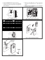
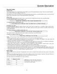
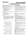
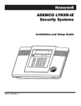
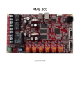
K14400V1 8/08 Rev A ADEMCO 5800WAVE Wireless Siren Module INSTALLATION AND SETUP GUIDE GENERAL INFORMATION The 5800WAVE (Figure 1) is a wireless siren module that contains an RF receiver and transmitter. The 5800WAVE provides the following features: • Compatible with the LYNXR Rev 10 or higher (with RF enrollment) and LYNXR-EN self-contained controls or with any other control that supports a 5883 Transceiver Module. • Transmits module status, including mounting tamper, low battery, and AC loss to the control. • Transmits supervisory check-in message. • Provides temporal 3 pulse sounding during fire alarms (which indicates evacuation of the premises). • AC powered and mounts on any standard duplex receptacle that is dedicated for use by this device. • Contains a rechargeable battery that provides up to 12 hours of standby operation in the event of AC loss. LED Activates Upon Yellow Normally off. Blinks to indicate that an RF message is being sent by the 5800WAVE. On steady during RF Link test. Green Normally on (lighted) when AC power is present. On when the system is armed. Off when the system is disarmed. During RF Link test, on indicates poor RF transmission. Red INSTALLATION The 5800WAVE must be powered overnight for the battery to reach full capacity. Connecting the Battery and Setting the House ID ! When separating the case front from the back use care not to damage the wire leads connected to the sounder and circuit board. Refer to Figure 2. 1. Remove the four screws located in the back of the unit. 2. Separate the case front from the back. 3. Check that the standby battery is held securely in place by the two battery clips as shown in Figure 2. 4. Plug the standby battery connector into the PCB connector as shown in Figure 2. 5. Set DIP switches 4-8 to the appropriate House ID (1-31) See Figure 3. The House ID set by the DIP switches should match that entered in the control. 6. Close the 5800WAVE’s case and reinstall the four screws removed in step 1. Verifying the RF Link Dip switch 6 on the 5883 must be set to ON to enable its RF transmitter. The security system control must have the House ID set and must not be in the Test Mode or Programming Mode when checking the RF Link. 1. Plug the 5800WAVE into the AC receptacle at the desired location. The green LED will light indicating AC is present and the 5800WAVE is powered. The yellow LED will light for approximately 15 seconds. • If the red LED turns on, the RF link is bad. Relocate the 5800WAVE to another AC receptacle (closer to the control) and repeat step 1 to verify the RF Link. • If the red LED remains off, the RF link is good and you may complete the installation at this location. 2. Unplug the 5800WAVE and proceed to “Enabling Module Supervision”. Enabling Module Supervision The 5800WAVE is supervised by the control for loss of RF check-in transmissions, low battery, loss of AC, and mounting tamper. The 5800WAVE reports AC loss and low battery as Low Battery to the control (and will not cause an alarm when the control is armed). If an AC loss condition exists “Low Battery” is displayed on the control keypad (with the programmed zone number) and the Green LED on the 5800WAVE is off. Program the 5800WAVE in the control as a zone and enroll its serial number as described using the installation and setup guide supplied with the control and the information below. Note the following when enrolling: Zone type = 5 (trouble by day / alarm by night) Input type = 3 (Supervised RF)…..Loop number = 1 1. When prompted for the serial number, you can either enter it manually or transmit from the device. a. To enter the serial number manually, read the number from the label on the device and enter it via the control’s keypad (referring to the zone programming section of the Installation and Setup Guide for the control). b. To transmit the serial number, plug the 5800WAVE into an AC receptacle. Within 15 seconds, place the tamper magnet next to the tamper position-indicator lines on the case (Figure 4) and wait until the yellow LED turns off, and then remove the magnet to cause a transmission. The yellow LED will flash when the transmission is sent. 2. When the enrollment is complete, exit programming mode and unplug the 5800WAVE. Proceed to step 3 if mounting tamper is desired. Otherwise proceed to “Completing Installation”. 3. Mount the magnet (using the screws supplied) to the wall, adjacent to the case, between the tamper position indicator lines as shown in Figure 4. Verifying Tamper Operation (if used) 1. Plug the 5800WAVE into the AC receptacle. Wait until the yellow LED turns off and clear any tamper fault caused by the 5800WAVE from the control. 2. Unplug the 5800WAVE from the AC receptacle and verify that the control now indicates the tamper fault. Completing Installation 1. Remove the screw that secures the cover plate to the duplex receptacle. Leave the cover plate in place on the receptacle as shown in Figure 5. 2. Plug the 5800WAVE back into the AC receptacle. 3. Insert the hold down screw (supplied) in the 5800WAVE mounting hole and secure the case to the receptacle as shown in Figure 5. 4. When the yellow LED turns off, arm the control and verify that the red LED turns on. Then disarm the control. 5. With the control in the TEST Mode, test the 5800WAVE sounder by causing an alarm. SIREN WIRE HOLD DOWNS GREEN YELLOW LED LED RED LED 1 2 ON OFF 3 4 5 6 7 8 OUTLET INDEXER BATTERY SIREN + + BATTERY CLIPS Figure 1. 5800WAVE Siren Module DIP SWITCH POSITIONS 4 5 6 7 8 House ID DIP SWITCH POSITIONS 4 5 6 7 8 0 1 2 3 4 5 6 7 8 9 10 11 12 13 14 15 – – – – – – – – – – – – – – – – 16 17 18 19 20 21 22 23 24 25 26 27 28 29 30 31 ON ON ON ON ON ON ON ON ON ON ON ON ON ON ON ON – – – – ON ON ON ON – – – – ON ON ON ON – – ON ON – – ON ON – – ON ON – – ON ON – ON – ON – ON – ON – ON – ON – ON – ON – – – – – – – – ON ON ON ON ON ON ON ON BATTERY TERMINAL BLOCK CONNECTOR (NOT USED) Figure 2. Battery and Siren Connection Points House ID – – – – – – – – ON ON ON ON ON ON ON ON JUMPER (DO NOT REMOVE) 5800WAVE-004-V1 5800WAVE-001-V0 MOUNTING HOLE – – – – ON ON ON ON – – – – ON ON ON ON – – ON ON – – ON ON – – ON ON – – ON ON – ON – ON – ON – ON – ON – ON – ON – ON “–“ Indicates “OFF.” 3 TAMPER POSITION INDICATOR LINES 4 5 6 HOUSE ID 16 SHOWN 5800WAVE-003-V0 1 2 ON OFF SWITCHES 1,2,3 MUST BE SET TO OFF 8 5800WAVE-005-V0 7 Figure 4. Optional Tamper Magnet Installation Figure 3. DIP Switch Settings RECEPTACLE COVER PLATE IN POSITION 5800WAVE-002-V1 MOUNTING SCREW Figure 5. Final Installation -2- SPECIFICATIONS Dimensions: 7.5" W x 4.5" H x 2.25" D. 191mm W x 114mm H x 57mm D. Input Voltage: 120VAC Current: 217mA Typical Range: 200ft (60m) nominal indoors (the actual range to be determined with the security system in the TEST mode). Operational Temperature: 32° to 122° F. Siren Output Level: 77.3dB @ 10 ft. TO THE INSTALLER Regular maintenance and inspection (at least annually) by the installer and frequent testing by the user are vital to continuous satisfactory operation of any alarm system. The installer should assume the responsibility of developing and offering a regular maintenance program to the user, as well as acquainting the user with the proper operation and limitations of the alarm system and its component parts. Recommendations must be included for a specific program of frequent testing (at least weekly) to insure the system's operation at all times. Federal Communications Commission (FCC) Part 15 The user shall not make any changes or modifications to the equipment unless authorized by the Installation Instructions or User's Manual. Unauthorized changes or modifications could void the user's authority to operate the equipment. CLASS B DIGITAL DEVICE STATEMENT NOTE: This equipment has been tested and found to comply with the limits for a Class B digital device, pursuant to part 15 of the FCC Rules. These limits are designed to provide reasonable protection against harmful interference in a residential installation. This equipment generates, uses and can radiate radio frequency energy and, if not installed and used in accordance with the instructions, may cause harmful interference to radio communications. However, there is no guarantee that interference will not occur in a particular installation. If this equipment does cause harmful interference to radio or television reception, which can be determined by turning the equipment off and on, the user is encouraged to try to correct the interference by one or more of the following measures: • • • • Reorient or relocate the receiving antenna. Increase the separation between the equipment and receiver. Connect the equipment into an outlet on a circuit different from that to which the receiver is connected. Consult the dealer or an experienced radio/TV technician for help. This Class B digital apparatus complies with Canadian ICES-003. Cet appareil numérique de la classe B est conforme à la norme NMB-003 du Canada. FCC/IC STATEMENT This device complies with Part 15 of the FCC rules and RSS 210 of Industry Canada. Operation is subject to the following two conditions: (1) This device may not cause harmful interference, and (2) This device must accept any interference received, including interference that may cause undesired operation. Cet appareil est conforme à la partie 15 des règles de la FCC & de RSS 210 des Industries Canada. Son fonctionnement est soumis aux conditions suivantes: (1) Cet appareil ne doit pas causer d' interferences nuisibles. (2) Cet appareil doit accepter toute interference reçue y compris les interferences causant une reception indésirable. -3- For the latest warranty information, please go to: http://www.security.honeywell.com/hsc/resources/wa 2 Corporate Center Drive, Suite 100 P.O. Box 9040, Melville, NY 11747 Copyright 2008 Honeywell International Inc. ÊK14400V1tŠ K14400V1 8/08 Rev. A