1
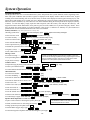
System Operation
Security Codes
Installer Code
The installer programs the 4-digit Installer Code initially as part of the programming procedure. The factory default Installer
Code is 4-1-1-2, but may be changed in field *20.
The Installer Code is the only code that can enter Programming mode and also, in normal operation mode, is used to enter the
Master Code, which allows access to the normal functions of the system.
Master Code
In normal operation mode, the Installer Code is used to enter the 4-digit Master Security Code using the keypad:
To enter/change the Master code by installer, enter:
Installer Code + [CODE key] + [02] + desired 4-digit Master Code
To change the Master code by master, enter:
Current Master Code + [CODE key] + [02] + new Master Code + new Master Code again
Secondary User Codes
In normal operation mode, the Master Security Code can be used to assign up to 6 secondary 4-digit security codes,
including a Babysitter Code and a Duress Code. The Master Code can also be used to remove secondary codes from the
system (individually).
To assign (or change) a secondary security code, enter:
Master Code + [CODE key] + User # (03–08) + desired Secondary Code
The system will emit a single beep when each secondary code has been successfully entered.
To delete a secondary security code, enter:
Master Code + [CODE key] + User # (03–08)
Notes:
All Master and Secondary security codes permit access to the system for arming, disarming, etc.
• The Installer Code can disarm the system only if it was used to arm it. In addition, the Installer Code cannot disarm the
system if it was armed by pressing and holding a Quick-Arm button.
• Babysitter Code is User Code No. 7; i.e., it can disarm the system only if it was used to arm it. In addition, the Babysitter
Code cannot disarm the system if it was armed by pressing and holding a Quick-Arm button.
• Duress code is User Code No. 8. When this is used to perform any system operation, a special code is sent to the
monitoring station. Instruct users to be careful not to use this code for normal usage.
• If a secondary code is inadvertently repeated for different users, the lower user number will take priority.
• Opening and closing reports are sent for the Installer Code as No. 01, with the appropriate subscriber number. Master Code
and set of secondary user codes are sent as Nos. 02 and 03–08, respectively, in Contact ID® format (with the appropriate
user number); in 4+2, it is 1–8. Quick arming is reported as user 00.
Panic Keys
There are three panic key pairs that, if programmed, can be used to manually initiate alarms and send a report to the central
station.
Each can be individually programmed for 24-hour silent, audible, personal or fire emergency responses. The panic function is
activated when both keys of the appropriate key pair are pressed at the same time.
The panic functions are identified by the system as follows:
Keys
Displayed as Zone
[1] & [*]
95
[*] & [#]
99
[3] & [#]
96
Important: For the silent panic functions to
be of practical value, the system must be
connected to a central station.
–39–
System Operation
Keypad Functions
The keypad allows the user to arm and disarm the system, and perform other system functions, such as bypassing zones.
Zone and system conditions (alarm, trouble, bypass) are displayed in the display window. When an alarm occurs, keypad
sounding and external sounding will occur, and the zone(s) in alarm will be displayed on the keypad. Pressing any key will
silence the keypad sounder for 10 seconds (only once). Disarming the system will silence both keypad and external sounders.
When the system is disarmed, any zones that were in an alarm condition during the armed period will be displayed (memory
of alarm). To clear this display, simply repeat the disarm sequence (enter the security code and press the OFF key). The
keypad also features chime annunciation, and 3 panic key pairs for silent, audible, fire or personal emergency alarms. These
keys can notify the central station of an alarm condition, if that service is connected. A summary of system functions is
provided below for more detailed information refer to the User's Manual.
Security Functions (Empty boxes represent the user’s security code)
Checking system status: -- STATUS (high level messages); press STATUS again for secondary messages
To arm in STAY mode: To restart exit delay: ------
+
STAY
(or installer code + [3])
STAY
(applies only if system is armed in Stay mode)
To arm in AWAY mode: To arm with NO DELAY:
To arm if Quick Arm is programmed:
+
AWAY
+
AWAY
or
AWAY
(or installer code + [2])
or
To disarm the system and silence alarms:
+
To bypass a zone(s): -------
+
To stop recording before end of 20 seconds:
OFF
To play back a message: - FUNCTION + PLAY
Volume Control
To adjust message playback/system announcement volume:
+
FUNCTION
NO DELAY
OFF
+ 2-digit zone number(s)
BYPASS
To turn Chime mode on or off: FUNCTION + CHIME
Message Center
To record a message: ------ FUNCTION + RECORD
To mute system announcements:
+
STAY
(hold down for at least 2 seconds)
STAY
+
VOLUME
NOTE
If a 5827 or 5827BD Wireless keypad has been installed, it cannot be
used to activate message playback/recording, programming the real time
clock or scheduling remotely. In this case, you must use the master
keypad on the control panel to perform these functions.
FUNCTION
+
VOLUME
+ [3] or [6]
OFF
To restore/unmute announcement & volume: FUNCTION + VOLUME + [3] or [6]
Other Functions
To set the time and date: + FUNCTION + [63]
To set the scheduling: -----
+
To activate or deactivate X-10 devices 1-6:
+ [64]
FUNCTION
FUNCTION
+
LIGHTS ON
To activate or deactivate X-10 devices 7 & 8:
+
*+
To add a user code: -------
CODE
*+
+
TEST
To turn Test mode off: ----
+
OFF
To use the defined AUX function: Press and hold
To define AUX function: -
+
LIGHTS OFF
AUX
FUNCTION
CODE
To flash (switch between two calls using call waiting):
To enable/disable (toggle) ringer: [#] +
+
or
LIGHTS OFF
+ dev. no.
key 2 secs (4 beeps) +
+
AUX
+ action separated by +
AUX
AUX
To return the keypad to telephone mode after disarming the system: [#] +
–40–
AUX
terminated by +
AUX
+
AUX
NOTE
The ARMED and READY LEDs blink alternately
when the Speaker Phone is active.
OFF
VOLUME
LIGHTS ON
+ user number (* master code)
To send message to pager: Press and hold AUX key 2 seconds (4 beeps)
Speaker Phone Operation (LYNXR-EN Only)
To place a call or answer a call using the speaker phone: [#] + AUX
To hang up and exit speaker phone mode:
+
FUNCTION
+ device number
+ user number + user’s code (*master code)
To delete a user code (except Master Code):
To turn Test mode on: ----
or
AUX
System Operation
Remote Phone Control Feature
The remote phone control feature, which must be enabled in field *91, allows the user to access the security system from any
off-site touch-tone telephone. The control will pick up the incoming call, based on the ring count specified in field *95, and
will announce “SYTEM” every three (3) seconds for the next eight (8) seconds. During this period the panel will wait for a
valid User Code to be entered. If a valid User Code is not entered or the eight (8) second period expires a modem tone will be
generated for remote programming (Compass Downloading). If a valid User Code has been entered, the control will
announce the current system status and/or beeping sounds.
Keypad Functions
Remote Phone Control Feature
To remotely disarm system:
+ [1]
+ [2]
To remotely arm in AWAY mode:
To remotely arm in STAY mode:
+ [3]
+ [2] or [3] + [0]
To remotely arm in AWAY or STAY with no delay:
Quick Arm Note:
The installer code
and babysitter code
cannot disarm the
system if armed by
Quick Arm method.
To remotely activate X-10 devices 1-6: [#] + [4] + device no.
+ [#] + [4] + device no.
To remotely activate X-10 devices 7 & 8:
To remotely deactivate X-10 devices 1-6: [#] + [7] + device no.
+ [#] + [7] + device no.
To remotely deactivate X-10 devices 7 & 8:
To remotely Bypass zones:
+ [6] + zone no.
To remotely activate Forced Bypass:
+ [6] + [#]
To remotely check system status: [*]
To end remote phone control session: Hang Up or
8/
+ [9]
Alarm audio verification cannot be used for UL installations.
Alarm Audio Verification (Two-Way Voice Feature)
This feature allows the central station operator to listen, talk to or conduct a two-way conversation with an individual(s) at
the premises. It also assists the operator in gathering information about the nature and location of the alarm that may be
helpful in responding to police and fire departments. All LYNXR-Series control panels are capable of supporting the TwoWay Voice feature, however only the LYNXR-EN has this feature built in. The LYNXR/LYNXR24 requires the installation
of the Audio Verification Module (LYNX-AVM). For further information regarding the LYNXR/LYNXR24 Two Way
Voice Feature refer to the LYNX-AVM Installation and Setup Guide. The LYNXR-EN does not make system
announcements when the Two-Way voice feature is active.
Activation
The LYNXR-EN sends the "alarm message" followed by a "Listen-in-to-Follow message" (Contact ID code 606) to the
Central Station. The Listen-in-to-Follow message causes the Central Station's digital receiver to temporarily hold the
phone line for approximately 1-minute. When the LYNXR-EN receives the "kissoff" from the central station, indicating
that the alarm message has been received, the Two-Way Voice (AVM) feature is activated in the (default) “Listen
Mode” and sirens and keypad sounds are discontinued. The LYNXR-EN transmits a beep acknowledgment to the
Central Station, once per second. The beep alternates between two tones and indicates that the LYNXR-EN is waiting for
a session command from the Central Station operator. Once a command is issued the beep acknowledgement is
discontinued, however, if a command is not issued within two minutes the system will “time out” and the call will be
terminated.
–41–
System Operation
Operator Commands
The Central Station operator begins the session, which last 5 minutes, by entering one of the valid AVM commands shown in the
table below. The session may be extended 5 minutes, without changing the operating mode, by pressing the [7] key on the touchtone phone. Selecting another operating mode also resets the session an additional 5 minutes. During the last minute of the 5
minute, session, the LYNXR-EN generates two beeps every 30 seconds to alert the Central Station operator that the session is
about to time out. The Central Station operator may then extend the session by pressing the [7] key on the touch-tone phone. If
the session is not extended the phone line is disconnected, and the session is ended. Sessions may be ended at any time by
pressing the [9] key on the touch-tone phone. The AVM modes are described as follows:
Note:
Key
1
2
When entering AVM commands make sure the Central Station receiver has been disconnected from the
phone line, otherwise AVM commands may not go through.
Function
Talk Mode: Pressing the [1] key on the touch tone phone, enables one-way voice communication from the central station to the
violated premises, and allows the operator to talk communicate through the LYNXR-EN speaker. In this mode the ARMED
(red) and READY (green) LEDs blink alternately.
VOX (Voice) Mode: Pressing the [2] key on the touch-tone phone, enables two-way voice communications between the central
station and the violated premises. In this mode the ARMED (red) and READY (green) LEDs blink alternately.
7
Listen Mode: Pressing the [3] key on the touch-tone phone, enables one-way audio from the violated premises to the central
station. The Listen Mode is the start up default mode of the voice feature and allows the operator to listen through the LYNXR-EN
microphone. This mode does not affect the existing LED pattern.
Extends the session 5 minutes without changing its operating mode.
9
Ends the session and disconnects the phone line.
3
–42–
System Operation
Powerline Carrier Devices (e.g. X-10 devices)
If Powerline Carrier Devices are used, two keypad entries available to the user are included. They can manually activate or
deactivate the device(s) for starting or stopping some action, such as turning lights on or off, etc.
These keypad entries are:
Security Code* + [#] + [4] + Device # activates (starts) that device.
Security Code* + [#] + [7] + Device # de-activates (stops) that device.
* Code is required for devices 7 and 8. Code is not required for devices 1-6.
Exit Error Alarm Displays
If programmed:
• A display of "CA" and a zone indication will appear if an exit or interior zone contained a fault during closing at the
time the exit delay ended (e.g., exit door left open), but the system was disarmed during the entry delay time. The
alarm sounder and keypad sound continuously, but stop when the system is disarmed. No message will be transmitted to
the central station.
• A display of "EA" and a zone indication will appear if an exit or interior zone contained a fault during closing at the
time the exit delay ended, but the system was NOT disarmed during the entry delay time. The alarm sounder and
keypad sound continuously until the system is disarmed (or timeout occurs). An Exit Alarm message is sent to the central
station.
• The "EA" display, etc. will also result if an alarm from an exit or interior zone occurs within two minutes after the end of
an exit delay.
In any of the above cases, use a second OFF sequence (code plus OFF key) to clear the display.
Trouble Conditions
The word "FAULT" on the keypad's display, accompanied by a rapid "beeping" at the keypad, indicates that there is
a trouble condition in the system. Pressing any key can silence the audible warning sound. Instruct users to call for
service immediately upon seeing any of the following messages.
"Fault" and "Battery" Displays
• A display of "FAULT" and one or more zone numbers indicates that a problem exists with the displayed zone(s) and
requires attention.
After correcting the problem, the display can be cleared by entering the security code plus the OFF key twice.
• The fault condition may also be caused by some change in the environment that prevents the built-in receiver from
receiving signals from a particular wireless sensor.
• A display of "LOW BAT" with no zone number indicates that the system's backup battery is weak.
• A display of "LOW BAT" with a zone number and a once-per-45 seconds "beeping" at the keypad indicates that a
low battery condition exists in the wireless sensor displayed (zone "00" indicates a wireless button/keypad). If the battery is
not replaced within 30 days, a “FAULT” display may occur.
Power Failure
• If there is no display at all, and both indicators are not lit, operating power for the system has stopped and the system is
inoperative.
• If the display is lit and the AC display is off, the system is operating on battery power only.
• During an AC power loss, the backlighting will turn off and the indicators will flicker slightly to minimize deep discharge
of the battery.
Other Displays
dI = Busy-Standby: Displayed upon power-up. After approximately 1 minute* the green “READY” LED should light. If
the “dI” remains displayed for more than 1 minute, the system is disabled.
* To bypass the 1-minute delay, press [#] + [0].
CC = Modem Comm: The system is in communication with the central station for change of function or status verification.
FC = Comm. Failure: A communication failure has occurred. This message clears only when the system is subsequently
armed.
90 = RF Jam: The system has detected an RF jamming condition or excessive interference.
PH = Speaker Phone Mode: The system is in Speaker Phone mode.
PC = Phone Control: The remote Phone Control feature is active.
–43–