1
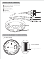
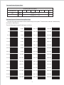
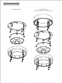
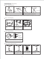
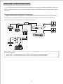
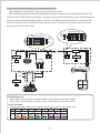
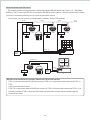
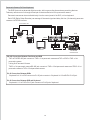
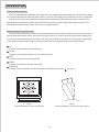
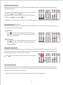
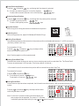
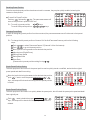
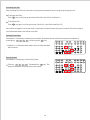
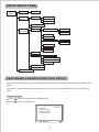
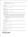
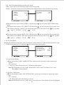
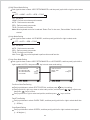
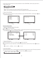
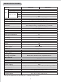
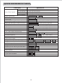
360° 4CH PANORAMA CAMERA
CMD2422S/SC
MERIT LILIN ENT. CO., LTD
http://www.meritlilin.com
66-CMD2422CSE
INSTRUCTION MANUAL
IMPORTANT SAFEGUARDS
CAUTION
RISK OF ELECTRIC SHOCK
DO NOT OPEN
CAUTION:
TO REDUCE THE RISK OF ELECTRIC SHOCK,
DO NOT REMOVE COVER (OR BACK)
NO USER SERVICEABLE PARTS INSIDE.
REFER SERVICING TO QUALIFIED
SERVICE PERSONNEL.
GRAPHIC SYMBOL EXPLANATION
The lightning flash with arrowhead symbol, within an equilateral
triangle, is intended to alert the user to the presence of
uninsulated "dangerous voltage" within the product's enclosure
that may be of sufficient magnitude to constitute a risk of electric
shock to persons.
The exclamation point within an equilateral triangle is intended
to alert the user to the presence of important operating and
maintenance (servicing) instructions in the literature
accompanying the unit.
CAUTION
RISK OF EXPLOSION IF BATTERY IS REPLACED
BY AN INCORRECT TYPE.
DISPOSE OF USED BATTERIES ACCORDING
TO THE INSTRUCTIONS
PREFACE
With 2 Megapixels (CMOS) camera and a 360 ° fisheye lens viewfinder, the 360 ° captured panoramic image is split
into four standard video signals (CVBS Port). Each image can be controlled by keyboard controller through RS-485
communication interface or through Lilin single-chip digital video recorder (DVR) Local Host RS-485 communication
interface, and control functions are similar to controlling 4 fast dome cameras. The new panoramic camera can be
from single 4-channel panoramic camera or serial linking to 64 panoramic cameras allowing expansion to 256channel video screen. Each channel can be set up to 128 preset points and perform automatic patrol (Auto-Pan).
The digital Pan/Tilt/Zoom (ePTZ) control is different from the traditional fast dome camera, there is no vibration,
noise and heat problem inherent in motor rotation. There are also no motor component reliability and life span issues.
The new 2 Megapixels 360 ° panorama camera, not only has bright smooth appearance, it timely switch to night
mode at low illumination showing clearly visible image with extra infrared illuminator. The best choice among
monitoring equipment.
FEATURES
Build-in 360 ° optical fisheye lens with focal length 1.25mm
Lens angle field of view: 185 ° ; Vertical = 185 ° ; Diagonal = 185 °
Effective Pixels
Input: 1600(H) x 1200(V) ; Output:4 x D1(N/P) 2:1 Interlace
Minimum Illumination
Color: 1 Lux (F2.0) ; Monochrome: 0.5 Lux (F2.0) ; 0 Lux at IR LED turn ON
White Balance: ATW / Manual / 3200 ° K / 5600 ° K / 6500 ° K
Auto Gain Control
Shutter Speed: 1/60 ~ 1/10,000s
Electronic Pan, Tilt & Zoom:
1. Panning Range: 360 ° Endless
2. Tilting Range: 90 °
3. Panning & Tilting Speed: Manual 0.15 ° /sec ~ 120 ° /sec, Preset Position 1 ° /sec ~ 255 ° /sec
4. Panning & Tilting Mode: Manual, Auto, Manual Position, Sequential Position.
Control Interface: RS-485
Protocol: MLP2 / D-Protocol
Control Setting:
1. Build in DSP color camera.
2. Color / Mono Switch (IR Cut Filter): Day(Color) / Night(Mono) / Schedule
3. White Balance Control: Auto Tracing(ATW) & Manual(MTW)
4. 11 levels Brightness Adjustment & 12 levels Pedestal Adjustment
Up to 64 Panorama Camera configuration
Preset Position: 128 (Each channel)
Auto Mode: OFF / AUTO / SEQ. / TOUR
Self Run Mode: OFF / HOME / AUTO / SEQ. / TOUR
Schedule Mode: OFF / AUTO / SEQ. / TOUR / STOP
1
STRUCTURAL ELEMENT
4 port Video Out BNC Jacks - [4CH BNC Model]
RJ-45 Jack - [CAT5 Model]
RS-485 In/Out Terminal
Power In DC Jack (DC12V)
Camera Case
2M-Pixels 360 ° Panorama Camera
PANORAMA DOME CAMERA SETUP
DIP Switch Setting
1 2 3 4 5 6 7 8
ON
1 2 3 4 5 6 7 8
ON
2
RS-485 Protocol Switch
Camera System & ID Switch
RS-485 Protocol Switch Setting
DIP Switch Setting:
1. BAUD SEL 1
: Transmission speed selection 1
2. BAUD SEL 2
: Transmission Speed selection 2
3. PROTOCOL SEL 1
: Protocol selection 1
4. PROTOCOL SEL 2
: Protocol selection 2
5. PROTOCOL SEL 3
: Protocol selection 3
6. RS-485 IN-TML RES.
: RS-485 IN Terminal Resistor ON/OFF
7. RS-485 OUT-TML RES. : RS-485 OUT Terminal Resistor ON/OFF
8. NA
Note: Using Pelco D, please contact your nearest agent.
Transmission Speed Setting
BAUD RATE SELECTION
DIP SWITCH
1
2
2400 bps
ON
ON
4800 bps
OFF
ON
9600 bps
ON
OFF
Remark: Lilin Protocol control mode is N, 8, 1 Baud Rate : 9600 bps
Protocol Setting
PROTOCOL SELECTION
DIP SWITCH
3
4
5
MLP2 (MERIT LILIN PROTOCOL 2) VERSION
ON
ON
ON
PELCO D PROTOCOL
OFF
ON
ON
RS-485 In/Out Terminal Resistor Setting
Daisy Connection: Set RS-485 In and Out terminal resistor as ON. (Factory Initialize)
Parallel Connection: Set the front and last equipments terminal resistor as ON. The parallel connection
equipment in the middle set as OFF to keep the best transmitted status.
RS-485 Protocol DIP Switch of Lilin CMD2422S/CMD2422SC Series Setting
RS-485 Protocol DIP Switch Setting
DIP SWITCH
1
2
3
4
5
6
7
8
MLP2 Version
ON
OFF
ON
ON
ON
ON
ON
X
3
Panorama Camera System Switch
Camera System & ID Switch
DIP SWITCH
1
PAL
ON
2
3
Camera ID : 1 - 256
4
5
6
7
X
8
NTSC
OFF
Camera ID : 1 - 256
X
Panorama Camera ID Address Setting Refer Chart
Up to 64 4CH panoramic camera can be serial linking in one system. Therefore each channel is addressed by
ID switch for identification.
The 4CH Panorama Camera ID setting are as follows:
ON
1~4
1
ON
2
3
4
5
6
7
8
65~68
ON
5~8
1
1
2
3
4
5
6
7
8
69~72
1
2
3
4
5
6
7
8
73~76
1
2
3
4
5
6
7
8
77~80
1
2
3
4
5
6
7
8
81~84
1
2
3
4
5
6
7
8
85~88
1
2
3
4
5
6
7
8
89~92
1
2
3
4
5
6
7
8
93~96
1
2
3
4
5
6
7
8
97~100
1
2
3
4
5
6
7
8
101~104
1
2
3
4
5
6
7
8
105~108
1
2
3
4
5
6
7
8
109~112
1
2
3
4
5
6
7
8
113~116
1
2
3
4
5
6
7
8
117~120
1
7
133~136
8
1
1
1
1
1
1
1
1
1
1
1
1
2
3
4
5
6
7
8
121~124
1
2
3
4
5
6
7
137~140
8
3
4
5
6
7
8
125~128
1
3
4
5
6
7
8
193~196
1
1
2
3
4
5
6
7
141~144
8
1
2
3
4
5
6
7
8
197~200
3
4
5
6
7
145~148
8
1
2
3
4
5
6
7
8
201~204
3
4
5
6
7
149~152
8
1
2
3
4
5
6
7
8
205~208
3
4
5
6
7
153~156
8
1
2
3
4
5
6
7
8
209~212
3
4
5
6
7
157~160
8
1
2
3
4
5
6
7
8
213~216
3
4
5
6
7
161~164
8
1
2
3
4
5
6
7
8
217~220
3
4
5
6
7
165~168
8
1
2
3
4
5
6
7
8
221~224
3
4
5
6
7
169~172
8
1
2
3
4
5
6
7
8
225~228
3
4
5
6
7
173~176
8
1
2
3
4
5
6
7
8
229~232
3
4
5
6
7
177~180
8
1
2
3
4
5
6
7
8
233~236
3
4
5
6
7
181~184
8
1
2
3
4
5
6
7
8
237~240
3
4
5
6
7
185~188
8
1
2
3
4
5
6
7
8
241~244
3
4
5
6
7
189~192
8
4
1
5
6
7
8
1
2
3
4
5
6
7
8
1
2
3
4
5
6
7
8
1
2
3
4
5
6
7
8
1
2
3
4
5
6
7
8
1
2
3
4
5
6
7
8
1
2
3
4
5
6
7
8
1
2
3
4
5
6
7
8
1
2
3
4
5
6
7
8
1
2
3
4
5
6
7
8
1
2
3
4
5
6
7
8
1
2
3
4
5
6
7
8
2
3
4
5
6
7
8
2
3
4
5
6
7
8
2
3
4
5
6
7
8
ON
2
3
4
5
6
7
8
245~248
1
ON
2
3
4
5
6
7
8
249~252
ON
2
4
ON
ON
2
3
ON
ON
2
2
ON
ON
2
1
ON
ON
2
8
ON
ON
2
7
ON
ON
2
6
ON
ON
2
5
ON
ON
2
4
ON
ON
2
3
ON
ON
2
2
ON
ON
2
1
ON
ON
ON
2
ON
2
ON
ON
ON
61~64
6
ON
ON
57~60
5
ON
ON
53~56
4
ON
ON
49~52
3
ON
ON
45~48
2
ON
ON
41~44
1
1
ON
ON
ON
37~40
129~132
8
ON
ON
33~36
7
ON
ON
29~32
6
ON
ON
25~28
5
ON
ON
21~24
4
ON
ON
17~20
3
ON
ON
13~16
ON
2
ON
ON
9~12
1
1
ON
2
3
4
5
6
7
8
253~256
1
INSTALLATION
Embedded Mounting
Attached Mounting
(Only applicable in CAT5 model option)
5
Embedded Mounting (False Ceiling)
Step 1. Ceiling Preparation
Drill a 3/32" (2.4mm) hole at the center of the chosen
area.
Use a pencil and a compass to mark a circle 3.6"~4.1"
(90~105mm) in diameter and cut the circle.
Note: Due to camera body cable tap hole position, drill hole bigger than 3.6"(90mm) but smaller than fix ring inner diameter.
Step 2. The Ceiling Ring
90°
125mm
105mm
125mm
Place fixed ring on the
ceiling.
Tighten the four tapping
screws into the ceiling or
four machine screws with
four screw nuts.
Fixed ring size and screw
location.
Step 3. Camera Setting
1 2 3 4 5 6 7 8
ON
RS-485 Protocol
Switch
1 2 3 4 5 6 7 8
ON
Camera System
& ID Switch
Note: Refer to
section P2~4
Separate rubber sheet from the camera main body.
Set Panorama Camera ID, RS-485 Protocol and Camera
system.
TXDI+
TXDI TXDO+
TXDO GND
Step 4. Control Cable Connection
Connect RS-485 cable.
Connect DC12V Power
cable. (Suggest to use the
ADAPTOR from the factory.)
6
Connect four video signal
cable. [4CH BNC Model]
Connect RJ-45 cable.
[CAT5 Model]
Step 5. Install Camera Body and Ring
Attach the camera body
to the fixed ring.
Notice: Camera body screw
hole should be align to fixed
ring’s latch position.
Tighten the two screws to
fix the camera body.
Step 6. Install Decorative Ring
Put the decorative ring on
the camera body.
Notice: Ring’s positioning
column should be between
camera body positioning
column and screw nut.
Rotate the decorative ring
counter clockwise until its
position column touch the
camera body positioning
column. Tighten the 4
screws.
Installation is complete.
Attached Mounting (Fixed Ceiling) - [Option for CAT5 Model only]
Step 1. Fixed the Camera Base
90°
116mm
116mm
Attach the camera base to
ceiling.
Tighten the four tapping
screws into the ceiling.
Camera base size and
screw location.
Step 2. Fixed the Ring
90°
125mm
105mm
125mm
The fixed ring placed on
the base.
Tighten the four screws
into the base.
Fixed ring size and screw
location.
7
Step 3. Camera Setting
1 2 3 4 5 6 7 8
ON
RS-485 Protocol
Switch
1 2 3 4 5 6 7 8
ON
Camera System
& ID Switch
Note: Refer to
section P2~4
Separate rubber sheet from camera main body.
Set Panorama Camera ID, RS-485 Protocol and Camera
system.
TXDI+
TXDI TXDO+
TXDO GND
Step 4. Control Cable Connection
Connect RS-485 cable.
Connect DC12V Power
cable. (Suggest to use the
ADAPTOR from the factory.)
Connect RJ-45 cable.
[CAT5 Model]
Step 5. Install Camera Body and Ring
Attach the camera body to
the fixed ring.
Notice: Camera body screw
hole should be align to fixed
ring’s latch position..
Tighten the two screws to
fix the camera body.
Step 6. Install Decorative Ring
Put the decorative ring on
the camera body.
Notice: Ring’s positioning
column should be between
camera body positioning
column and screw nut.
Rotate the decorative ring
counter clockwise until its
position column touch the
camera body positioning
column. Tighten the 4
screws.
8
Installation is complete.
SYSTEM CONFIGURATION
Lilin’s Panorama camera Surveillance System is suitable for wide range of surveillance applications. With DVR
digital storage in the system, it can control the panoramic camera. Such flexibility means future expansion is easily
facilitated.
Panoramic Camera, Keyboard and 4CH DVR Configuration
Single Panoramic camera configuration: One Panorama Camera connects to one PIH-931D/932T. Telemetry
control is sent via twisted pair between Panoramic camera and Keyboard. 4 channel Video signal from the
panoramic camera is sent to multiplexer or quad and into monitor.
OR
4CH VIDEO
OUT
VIDEO
IN
VIDEO
OUT
VIDEO
IN
RS-485
Monitor
ADAPTOR
ZOOM AUTO
HOLD
PIH-624
COLOR QUAD
HIGH RESOLUTION
1
2
3
4
4/4
MENU
POWER
ON
OFF
Quad
AC
VIDEO
IN
VIDEO
OUT
VIDEO
IN
GND
TXDOTXDO+
TXDITXDI+
Monitor
DC12V
1
8
GND
2
7
3
6
4
5
ADAPTOR
AC
POWER
ALARM
DVR
06/02/15 12:00:00
PTZ MODE ID=000
R/T
Keyboard Controller
RS-485 Connection
7th pin TXDI+ of Connector Box connects to TXDI+ of RS-485 jack on panoramic camera.
8th pin TXDI- of Connector Box connects to TXDI- of RS-485 jack on panoramic camera.
9
Long distance Panoramic Camera with a Keyboard and 4CH DVR
( Applicable Model: CMD2422SC ; Video transmission distance: 300m)
When installing the panorama camera in long distance is required, may switch to panorama CAT5 camera. This
model has built-in video encoder converting 4-ch analogue video signal to CAT5 network signal. With RJ-45 network
connector, and transmitted through the network cable up to 300 meters transmission distance. Just connect video
decoder at the other end or at the DVR 4CH video input front-end to restore the analog video and have complete
panorama camera 4-ch video signal.
Plug at DVR side
CH4
CH3
CH2
CH1
Plug at Camera side
CH4
CH3
CH2
CH1
~
~
8
7
6
5
4
3
2
1
8
7
6
5
4
3
2
1
Converter
1000feet
1
RS-485
8
1
4CH VIDEO
OUT
8
ADAPTOR
ADAPTOR
RJ-45
RJ-45
AC
GND
TXDOTXDO+
TXDITXDI+
AC
DC12V
1
8
GND
2
7
3
6
4
5
ADAPTOR
AC
POWER
ALARM
DVR
VIDEO
OUT
VIDEO
IN
06/02/15 12:00:00
PTZ MODE ID=000
R/T
Monitor
Keyboard Controller
RS-485 Connection
7th pin TXDI+ of Connector Box connects to TXDI+ of RS-485 jack on panoramic camera.
8th pin TXDI- of Connector Box connects to TXDI- of RS-485 jack on panoramic camera.
RJ-45 Connection
*Should pay attention to the RJ-45 connectors at both ends, must be the same color order.
Pin
Signal
Color
1
2
CH1
White/Orange
stripe
3
4
CH2
Orange
solid
White/Green
stripe
5
6
CH3
Green
Solid
White/Blue
stripe
7
8
CH4
Blue
solid
10
White/Brown
stripe
Brown
Solid
Multiple Domes means that more than one panoramic camera is linked in the system. Each panoramic camera
connects to next panoramic camera forming a serial linking. Each panoramic camera has an individual ID dip switch,
which allows the keyboard to identify each panoramic camera and make command. Sometimes it is more convenient
to wire a telemetry system in star configuration rather than daisy chain. To do this a PIH-804Ⅲ data distributor is
necessary. It takes an output from a keyboard or a matrix and splits the single data line into 4 separate data lines.
One Keyboard can control up to 64 cameras total of 256 channels.
4CH VIDEO OUT
4CH VIDEO
OUT
4CH VIDEO
OUT
4CH VIDEO
OUT
DC12V
DC12V
DC12V
DC12V
CAMERA 16
(61~64CH)
ADAPTOR
CAMERA 32
(125~128CH)
CAMERA 48
(189~192CH)
CAMERA 64
(253~256CH)
AC
4CH VIDEO
OUT
4CH VIDEO
OUT
4CH VIDEO
OUT
4CH VIDEO
OUT
DC12V
DC12V
DC12V
DC12V
CAMERA 2
(5~8CH)
CAMERA 18
(69~72CH)
CAMERA 34
(133~136CH)
CAMERA 50
(197~200CH)
4CH VIDEO
OUT
4CH VIDEO
OUT
4CH VIDEO
OUT
4CH VIDEO
OUT
DC12V
DC12V
DC12V
DC12V
CAMERA 1
(1~4CH)
CAMERA 17
(65~68CH)
O1+
O1GND
O2+
O2GND
O3+
O3GND
O4+
O4GND
GND
TXDOTXDO+
TXDITXDI+
CONTROL
CHAIN 1
CAMERA 33
(129~132CH)
CONTROL
CHAIN 3
CONTROL
CHAIN 2
DAISY CONFIGURATION
CAMERA 49
(193~196CH)
CONTROL
CHAIN 4
RS-485
DISTRIBUTER
PIH-804
OUT
DC 12V
RS-485
DATA
DISTRIBUTOR
ADAPTOR
DC12V
1
8
GND
2
7
3
6
4
5
AC
ADAPTOR
AC
POWER
ALARM
TXDITXDI+
06/02/15 12:00:00
PTZ MODE ID=000
R/T
4CH DVR
Keyboard Controller
RS-485 Connection Between PIH-804Ⅲ Data Distributor and Panoramic Camera
1st output TXDI1+ of PIH-804Ⅲ connects to TXDI+ of 1st panoramic camera and TXDI1- of PIH-804Ⅲ to TXDIof 1st panoramic camera.
Linking 2nd Panoramic Camera
TXDO+ of 1st panoramic camera connects to TXDI+ of 2nd panoramic camera and TXDO- of 1st panoramic
camera to TXDI- of 2nd panoramic camera.
RS-485 Connection Between PIH-804Ⅲ Data Distributor and Keyboard
7th pin TXDI+ of Connector Box connects to TXDO+ on RS-485 OUT jack of PIH-804Ⅲ
8th pin TXDI- of Connector Box connects to TXDO- on RS-485 OUT jack of PIH-804Ⅲ
11
Panoramic Camera with PC Control
PC telemetry remote controls panoramic camera with standard RS-485 data format (format: N, 8, 1 Baud Rate:
9600bps). The PC control port RS-232 is converted to RS-485 format by interface. User may use their own software
(protocol) or software provided by Lilin to control the panoramic camera.
In this system, you can connect up to 64 panoramic cameras, a total of 256 channels.
RS-485
RS-485
4CH VIDEO
OUT
RS-485
4CH VIDEO
OUT
ADAPTOR
CAMERA 1
(1~4CH)
ADAPTOR
4CH VIDEO
OUT
CAMERA 2
(5~8CH)
AC
ADAPTOR
CAMERA 3
(9~12CH)
AC
GND
TXDOTXDO+
TXDITXDI+
AC
NEXT
DOME
VIDEO
RS-232
RS-485
Interface
VIDEO
IN
IN
RS-232
PC
4CH VIDEO OUT
RS-485
AC
GND
TXDOTXDO+
TXDITXDI+
ADAPTOR
RS-232
RS-485
Interface
CAMERA
CH1
CH2
CH3
CH4
VIDEO
IN
RS-232
PC
RS-485 Connection Between Panoramic Camera and Conversion Interface
TXD+ of conversion interface RS-485 jack connects to TXDI+ of 1st panoramic camera and connect TXD- to
TXDI-.
Linking 2nd Panoramic Camera
TXDO+ of 1st panoramic camera RS-485 jack connects to TXDI+ of 2nd panoramic camera and TXDO- of 1st
panoramic camera to TXDI- of 2nd panoramic camera. 64 panoramic cameras can be linked through the
connection as shown.
12
Panoramic Camera, DVR and Keyboard
The DVR System is an advanced digital recorder, with long recording time and easy searching features.
Telemetry remote control is through twisted pair for data transmission to the panoramic camera.
Panoramic camera can be controlled directly from the control panel of the DVR, or from keyboard.
Each DVR (Digital Video Recorder) can manage 16 channels signal and daisy link four (16 channels) panorama
cameras via RS-485 interface.
4CH VIDEO OUT
RS-485
DVR
ADAPTOR
On
CAMERA 1
(1~4CH)
of f
VIDEO
1
GND
TXDOTXDO+
TXDITXDI+
9
AC
2
10
3
11
1
CA M ERA I N
5
4
12
13
6
14
7
15
8
V I DEO
OU T
16
Au d i o i n
Po w e r
A L A R M /r s 4 8 5
S -V I D E O
16
1
3
2
4
Au d i o
out
1
La n
AC 100~240V
8
POWER
ALARM
06/02/15 12:00:00
PTZ MODE ID=000
R/T
RJ-45
MONITOR
KEYBOARD
CONTROLLER
RS-485 Connection Between Fast Dome and DVR
TXD+ of DVR RS-485 jack connects to TXDI+ of 1st panoramic camera and TXD- of DVR to TXDI- of 1st
panoramic camera.
Linking 2nd Panoramic Camera
TXDO+ of 1st panoramic camera RS-485 jack connects to TXDI+ of 2nd panoramic camera and TXDO- of 1st
panoramic camera to TXDI- of 2nd panoramic camera.
RJ-45 Connection Between DVRs
"Keyboard Out" of 1st DVR connects to RJ-45 jack connects to "Keyboard In" of 2nd DVR's RJ-45 jack.
RJ-45 Connection Between DVR and Keyboard
"Keyboard In" of 1st DVR's RJ-45 jack connects to RJ-45 jack of keyboard.
13
OPERATION
Initial Power Up Inspection
After you completed the installation and initially power up, the panorama camera will perform self-test procedure,
the camera calibrates and checks the basic function, controlling the camera is possible after self-test is completed.
If preset positions and tours have been programmed into a panorama camera and the power is turned off, the
panorama camera will enter the Auto Scan mode once the power is turned on again (after self-test period). The
panorama camera will remain in Auto Scan until an operator cancels it.
Manual Operation (Pan/Tilt Control)
To control the pan and tilt movement of the panorama camera screen, simply use the joystick on the keyboard; to
pan the panorama camera screen. left push the joystick to the left, to tilt down pull the joystick down (towards you).
To move the panorama camera screen faster, push the joystick further in that direction, the joystick is proportional
to the speed of the panorama camera; a small movement will move the panorama camera screen slower.
1
2
3
4
5
UP
Push the joystick forward, the camera tilt up.
DOWN
Push the joystick down (towards you), the camera tilt down.
LEFT
Push the joystick left, the camera pan left.
RIGHT
Push the joystick right, the camera pan right.
DIAGONAL
Push the joystick diagonally, the camera moves to that direction (direction
on figure 1)
1
5
5
3
4
5
5
2
Figure 1
Relationship Between Joystick and Direction
Figure 2
Relationship Between Joystick and Rotation Speed
14
Panorama Camera Selection
Each panoramic camera has four surveillance panoramic image channels, the user can switch between image
channel and operation.
To select 1st Panorama Camera (Channel 1 of the first Camera)
Push key 1 followed by CAM key.
To select 64th Panorama Camera (Channel 4 of 16th Camera)
4
Push key 6
followed by CAM key.
LENS
WIPER
ICR
SPRAY
C.ESC
LIGHT
C.SET
CTRL1
180。
CTRL2
SEARCH
DVR
CAM
MATRIX
MON
PRESET
1
2
3
4
5
6
7
8
9
CLR
0
ENT
ALARM
RESET
SET
ESC
F1
F2
F3
SEQ
AUTO
PAN
FOCUS
NEAR
AUTO
FOCUS
F4
SHIFT
FOCUS
FAR
AUTO
IRIS
*When matrix system is used, select monitor before camera selection. Please refer to matrix system user manual.
Zoom Lens Control (Digital Zoom)
Each panoramic camera has four surveillance panoramic image channels, the user can control screen zoom in (or
out) image in each channel separately.
To Zoom In
Push
key. The viewing angle becomes narrower and
target will become enlarge on the screen. Zooming will stop
when the key is released.
LENS
WIPER
ICR
SPRAY
C.ESC
LIGHT
C.SET
CTRL1
180。
CTRL2
SEARCH
To Zoom Out
Push
key. The viewing angle becomes wider and target
will become smaller on the screen. Zooming will stop when
the key is released.
DVR
MATRIX
CAM
MON
PRESET
1
2
3
4
5
6
7
8
9
CLR
0
ENT
ALARM
RESET
SET
ESC
F1
F2
F3
SEQ
AUTO
PAN
FOCUS
NEAR
AUTO
FOCUS
F4
SHIFT
FOCUS
FAR
AUTO
IRIS
Horizontal 180 ° Instant Flip
Sometimes it is hard to use the joystick to control the camera tracking the target directly under the camera. The
instant flip key can rotate the camera 180 ° instantly. This allows the camera continue to track the target passing
directly under the camera. To operate 180 ° instant flip:
Push
。
180
CTRL 2
key on keyboard to flip the camera 180 ° horizontally.
LENS
WIPER
ICR
SPRAY
C.ESC
LIGHT
C.SET
CTRL1
180。
CTRL2
SEARCH
DVR
MATRIX
CAM
MON
PRESET
1
2
3
4
5
6
7
8
9
CLR
0
ENT
ALARM
RESET
SET
ESC
F1
F2
F3
SEQ
AUTO
PAN
FOCUS
NEAR
AUTO
FOCUS
SHIFT
FOCUS
FAR
AUTO
IRIS
Preset Positions Setting
Each panoramic camera can have 128 individual preset positions. Each preset stores the exact position of the
camera and automatic pan, tilt, zoom, focus and iris setting. Once the data is set, the preset can be recalled for
viewing, or the presets can be set for auto pan.
*Only the first 16 preset positions of panorama camera can be set to auto pan mode.
15
F4
1
Select Panorama Camera
Push key 1 followed by CAM key, confirming that first channel is selected.
Ex. To select 1st channel (Channel 1 of the first Camera) : 1 CAM keys
To select 64th channel (Channel 4 of the 16th Camera) : 6 4 CAM keys
2
Selecting Preset Position
Push key 1 followed by PRESET key, confirming that first preset position selected.
Ex. To select 1st preset position : 1 PRESET keys
To select 128th preset position : 1 2 8 PRESET keys
3
Joystick Control
Move the joystick to bring the camera to the desired view position.
1
5
5
3
4
5
5
4
Adjusting Lens
When set up preset point, adjust ZOOM IN and ZOOM OUT keys.
5
Setting Preset Speed
The speed the panorama camera travels to that preset position can be adjusted between 1 ° to 255 ° per second
(the factory default is 40 ° /sec).
To set speed as 10 ° /sec:
0
Push key 1
followed by F1 key, two beeps will be
heard confirming that speed is set.
2
LENS
WIPER
ICR
SPRAY
C.ESC
LIGHT
C.SET
CTRL1
180。
CTRL2
SEARCH
DVR
CAM
MATRIX
MON
PRESET
1
2
3
4
5
6
7
8
9
CLR
0
ENT
ALARM
RESET
SET
ESC
F1
F2
F3
SEQ
AUTO
PAN
FOCUS
NEAR
AUTO
FOCUS
F4
SHIFT
FOCUS
FAR
AUTO
IRIS
Note: Push key again to confirm speed entered.
6
Setting Preset Dwell Time
The dwell time means the time user wants to view on certain preset position under Auto Pan. The Preset Dwell
Time can be set between 0~255 seconds. (The factory default is 0 second.)
*If the dwell is set to 0 second then that position will be omitted from the Auto Scan Tour.
To set dwell to 5 second:
Push key 5 followed by F2 key.
Ex. To set dwell to 5 second: 5 F2 keys
To set dwell to 10 second: 1 0 F2 keys
7
LENS
WIPER
ICR
SPRAY
C.ESC
LIGHT
C.SET
CTRL1
180。
CTRL2
SEARCH
DVR
MATRIX
CAM
MON
PRESET
1
2
3
4
5
6
7
8
9
CLR
0
ENT
ALARM
RESET
SET
ESC
F1
F2
F3
SEQ
AUTO
PAN
FOCUS
NEAR
AUTO
FOCUS
F4
SHIFT
FOCUS
FAR
AUTO
IRIS
Storing Preset Data
Once the above steps have been completed, the information must be stored or it will not be memorized by the
system.
LENS
WIPER
ICR
SPRAY
C.ESC
LIGHT
C.SET
CTRL1
180。
CTRL2
SEARCH
Push key 1 followed by F3 key, two beeps will be heard
confirming that data is stored.
Note: For the first 16 presets on each panorama camera, the
above steps must be repeated. For presets 17~128 there
is a default speed and dwell setting so steps 5 and 6 are not required.
16
DVR
MATRIX
CAM
MON
PRESET
1
2
3
4
5
6
7
8
9
CLR
0
ENT
ALARM
RESET
SET
ESC
F1
F2
F3
SEQ
AUTO
PAN
FOCUS
NEAR
AUTO
FOCUS
SHIFT
FOCUS
FAR
AUTO
IRIS
F4
Recalling Preset Position
Once the required preset positions have been stored in a camera, they may be quickly recalled, returning the
camera to exact position.
LENS
WIPER
ICR
SPRAY
C.ESC
LIGHT
C.SET
CTRL1
180。
CTRL2
SEARCH
To recall 1st Preset Position:
Push key 1 followed by PRESET key. The panorama camera will
move to that position in speed of 360 ° /sec.
Ex. To recall 1st preset position : 1 PRESET keys
To recall 128th preset position : 1 2 8 PRESET keys
DVR
CAM
MATRIX
MON
PRESET
1
2
3
4
5
6
7
8
9
CLR
0
ENT
ALARM
RESET
SET
ESC
F1
F2
F3
SEQ
AUTO
PAN
FOCUS
NEAR
AUTO
FOCUS
F4
SHIFT
FOCUS
FAR
AUTO
IRIS
Changing Preset Data
In order to change any preset position from the one stored, the panorama camera must first be sent to that preset
position.
Ex. To change the 4th preset position of channel 3 of the 2nd Panorama Camera, perform the following
steps:
1
2
3
4
5
6
7
Push 7 CAM to select Panorama Camera 7 (Channel 3 of the 2nd camera).
Push 4 PRESET to go to 4th preset position.
Move joystick to bring camera to the desired view position.
Adjusting lens (Digital Zoom).
Setting preset speed
Setting dwell time
Store Data
(Please refer to preset position setting for step 3 ~ 7 )
Single Preset Position Saving
The main purpose of this function is the preset position can be quickly stored or modified, and retain the original
preset speed and dwell time setting.
Move the joystick to bring the camera to the desired view position,
push SHIFT + want to save the preset number keys + PRESET + ENT
keys, two beeps will be heard confirming that new preset position
is saved.
LENS
WIPER
ICR
SPRAY
C.ESC
LIGHT
C.SET
CTRL1
180。
CTRL2
SEARCH
DVR
MATRIX
CAM
MON
PRESET
1
2
3
4
5
6
7
8
9
CLR
0
ENT
ALARM
RESET
SET
ESC
F1
F2
F3
SEQ
AUTO
PAN
FOCUS
NEAR
AUTO
FOCUS
F4
SHIFT
FOCUS
FAR
AUTO
IRIS
Single Preset Position Delete
The main purpose of this feature is to quickly delete the preset point, but still retain the preset point speed and dwell
time originally set.
Push SHIFT + want to delete the preset number keys + PRESET + CLR
keys, two beeps will be heard confirming that preset position is
deleted.
17
LENS
WIPER
ICR
SPRAY
C.ESC
LIGHT
C.SET
CTRL1
180。
CTRL2
SEARCH
DVR
MATRIX
CAM
MON
PRESET
1
2
3
4
5
6
7
8
9
CLR
0
ENT
ALARM
RESET
SET
ESC
F1
F2
F3
SEQ
AUTO
PAN
FOCUS
NEAR
AUTO
FOCUS
SHIFT
FOCUS
FAR
AUTO
IRIS
F4
Activating Auto Pan
When the Auto Pan function is activated, the panorama camera will auto touring the preset groups set.
To activate Auto Pan:
Push
key, confirming the activaed of Auto Pan. (Auto Pan Led will be lit.)
AUTO
PAN
To stop Auto Pan:
Push
key again, confirming the stop of Auto Pan. (Auto Pan Led will be Off.)
AUTO
PAN
Note: When an image is in auto pan mode, it cannot be controlled unless auto pan is turned off. But other image or
other panorama camera can still be controlled.
Deleting Preset Data
Sometimes it is necessary to delete the stored data. All the data can be cleared from a panorama camera by
0
1
1
pressing key, 9
following by the CLR key.
LENS
WIPER
ICR
SPRAY
C.ESC
LIGHT
C.SET
CTRL1
180。
CTRL2
SEARCH
*Channel 1~4 of the panorama camera from all 128 preset data
will be erased.
DVR
CAM
MATRIX
MON
PRESET
1
2
3
4
5
6
7
8
9
CLR
0
ENT
ALARM
RESET
SET
ESC
F1
F2
F3
SEQ
AUTO
PAN
FOCUS
NEAR
AUTO
FOCUS
F4
SHIFT
FOCUS
FAR
AUTO
IRIS
Reboot System
Sometimes it is necessary to reboot the system.
0
1
3
Push key 9
, followed by the
beeps will be heard confirming reboot the system.
CLR
key. Two
18
LENS
WIPER
ICR
SPRAY
C.ESC
LIGHT
C.SET
CTRL1
180。
CTRL2
SEARCH
DVR
CAM
MATRIX
MON
PRESET
1
2
3
4
5
6
7
8
9
CLR
0
ENT
ALARM
RESET
SET
ESC
F1
F2
F3
SEQ
AUTO
PAN
FOCUS
NEAR
AUTO
FOCUS
SHIFT
FOCUS
FAR
AUTO
IRIS
F4
SETUP MENU TREE
SETUP
MENU
LANGUAGE
ENGLISH
DISPLAY
SETUP
DATE/TIME
TIME
DATE
DATE FORMAT
PAN/TILT ANGLE
AREA TITLE
DOME
SETTINGS
CAMERA
EXPOSURE MODE
AUTO
MANUAL
CONTRAST
SHARPNESS
AUTO
WHITE BALANCE
MANUAL
SATURATION
MIRROR
FLIP
DAY/NIGHT
PAN/TILT
HOME POSITION
SELF RETURN TIME
SELF RETURN MODE
AUTO MODE
PANORAMA
FACTORY INITIAL
SCHEDULE SETUP
PANORAMA CAMERA FUNCTION SETUP
Panorama Dome Camera (build-in fisheye lens) are equipped with superior day & night 2 Megapixels CMOS video
quality.
It provides on-screen display setup menu and all the functions can be selected and set through the OSD Setup
Menu.
Setup Menu Display
Press
Press
SET
ESC
key on the keyboard to recall Setup Menu.
key to exit setup menu.
LANGUAGE
<DISPLAY SETUP>
<DOME SETTINGS>
<SCHEDULE SETUP
19
ENGLISH
1>
Display Character Setup Menu
1. Display character Setup Menu
Press SET key into Setup Menu.
Push joystick down to select <DISPLAY SETUP>, and then press
Press ESC key to go back setup menu.
LANGUAGE
<DISPLAY SETUP>
<DOME SETTINGS>
<SCHEDULE SETUP
ENGLISH
SET
key to display character setup menu.
OFF
OFF
OFF
DATE/TIME
PAN/TILT/ANGLE
AREA TITLE
1>
2. Date and Time Setting
Push joystick down to select <DATE/TIME>, and then push joystick left or right to make selection:
OFF : No Date/Time on the monitor screen.
ON : Display Date/Time on the monitor screen. When selection is open, and then press SET key, date/time will
be set.
DATE/TIME
PAN/TILT/ANGLE
AREA TITLE
<ON>
OFF
OFF
DATE
TIME
DATE FORMAT
11/12/21
12:01:29
YY/MM/DD
(1) Date Adjustment
Push joystick down to select <DATE>, and then press SET key to setup date.
Push joystick left or right to adjust date, and then push joystick down to next item of date. Press
to go back.
SET
→ 11 / 12 / 21 → < DOWN > → 11 / 12 / 21 → < DOWN > → 11 / 12 / 21 →
→
ESC
→ 11 : 12 : 21 → < DOWN > → 11 : 12 : 21 → < DOWN > → 11 : 12 : 21 →
→
ESC
key
11 / 12 / 21
(2) Time Adjustment
Push joystick down to select <TIME>, and then press SET key to setup time.
Push joystick left or right to adjust time, and then push joystick down to next item of time. Press
to go back.
SET
ESC
ESC
key
11 : 12 : 21
(3) Date Format setting
Push joystick down to select <DATE FORMAT>, and then push joystick left or right to adjust format of date.
YY / MM / DD → MM / DD / YY → DD / MM / YY
20
3. PAN/TILT Angle Setting
Push joystick down to select <PAN/TILT/ANGLE>, and then push joystick left or right to select pan/tilt setup:
OFF : No Pan/Tilt Angle on the monitor screen.
ON : Pan/Tilt Angle on the monitor screen.
4. Area Title Setting
The area title function can display a direction indicator that appears in the picture to indicate the direction of the
location being shown on the screen. Text can also be displayed in the place of the direction indicators, if desired.
The direction indicators are N(north), NE(northeast), E(east), SE(south east), S(south), SW(southwest), W
(west), and NW(northwest).
Push joystick down to select <AREA TITLE>, and then push joystick left or right to select pan/tilt setup:
OFF : No Area Title on the monitor screen.
ON : Area Title on the monitor screen.
Display Function Setup Menu
1. Display the Camera Setting Menu
Press SET key to enter Setup Menu.
Push joystick down to select <DOME SETTINGS>, and then press
Press ESC key to go back setup menu.
LANGUAGE
<DISPLAY SETUP>
<DOME SETTINGS>
<SCHEDULE SETUP
ENGLISH
1>
<CAMERA>
DAY/NIGHT
<PAN/TILT
PANORAMA
SET
key to enter dome setting menu.
FACTORY INITIAL
DAY
1>
OFF
2. Camera Setting Menu
After getting in dome setting menu, push joystick down to select <CAMERA>, and then press
camera setting menu.
<CAMERA>
DAY/NIGHT
<PAN/TILT
PANORAMA
EXPOSURE MODE
CONTRAST
SHARPNESS
WHITE BALANCE
DAY
1>
OFF
SET
key to enter
<AUTO>
5
5
AUTO
(1) Exposure Mode Setting
Push joystick down to select <EXPOSURE MODE>, and then push joystick left or right to setup auto mode
or manual mode.
AUTO Exposure mode: This mode automatically adjusting electronic shutter speed according to the
brightness changes for best performance in high brightness area.
21
MANUAL Exposure mode: Press SET key into MANUAL Exposure setting menu, and then push joystick
left or right to make selection.
Manual exposure levels are 1~10 (gray ~ light).
(2) Contrast Setting
Push joystick down to select <CONTRAST>, and then push joystick left or right to adjust the image contrast
level.
Contrast ranges are 1~11 (weak ~ strong).
(3) Sharpness Setting
Push joystick down to select <SHARPNESS>, and then push joystick left or right to adjust the image
sharpness level.
Sharpness ranges are 1~10 (normal ~ high).
(4) White Balance Setting
Push joystick down to select <WHITE BALANCE>, and then push joystick left or right to setup auto mode
or manual mode.
Auto White Balance mode: Auto tracing white balance, suitable for 2500~9500K color temperature.
Manual White Balance mode: Manual white balance, suitable for 2500~9500K color temperature.
Select <MANUAL>, and press SET key into Manual White Balance mode adjustment image.
Push joystick down to select <R>, and then push joystick left or right to adjust the low color
temperature.(1~99)
Push joystick down to select <B>, and then push joystick left or right to adjust the high color
temperature.(1~99)
(5) Color Saturation Setting
Push joystick down to select <SATURATION>, and then push joystick left or right to adjust the image
saturation level.
Contrast ranges are 1~10 (low ~ high).
(6) Mirror Setting
Push joystick down to select <MIRROR>, and then push joystick left or right to setup mirror OFF or mirror
ON.
Note: Image will be Left / Right reverse.
(7) Flip Setting
Push joystick down to select <FLIP>, and then push joystick left or right to setup flip OFF or flip ON.
Note: Image will be Up / Down reverse.
3. Day/Night Control Setting
After entering dome setting menu, push joystick down to select <DAY/NIGHT>, and then push joystick left or
right to select mode.
DAY → NIGHT → SCHED.
22
DAY : Set to DAY mode and always produce color image.
NIGHT : Set to NIGHT mode and always produce monochrome image.
SCHED. : DAY/NIGHT switch automatically between Day mode and Night mode by schedule of time setting.
<CAMERA>
DAY/NIGHT
<PAN/TILT
PANORAMA
DAY→NIGHT
NIGHT→DAY
SCHED.
1>
OFF
18:00
06:00
Push joystick left or right to select <SCHED.>, and then press SET key into the day/night schedule setting
menu.
Push joystick down to select <DAY→NIGHT>, and then press SET key into time setting. Push joystick left or
right to select time of DAY→NIGHT. Then push joystick down to next item of date. Press ESC key to go back.
SET
→ 18 : 00 → < DOWN > → 18 : 00 →
→
ESC
18 : 00
Push joystick down to select <NIGHT→DAY>, and then press SET key into time setting. Push joystick left or
right to select time of NIGHT→DAY. Then push joystick down to next item of date. Press ESC key to go back.
SET
→ 06 : 00 → < DOWN > → 06 : 00 →
→
ESC
18 : 00
4. Pan/Tilt Setting Menu
After getting in dome setting menu, push joystick down to select <PAN/TILT>, and then push joystick left or right
to select channel number(1~4), then press SET key into the channel setting menu.
<CAMERA>
DAY/NIGHT
<PAN/TILT
PANORAMA
HOME POSITION
SELF RETURN TIME
SELF RETURN MODE
AUTO MODE
DAY
1>
OFF
OFF
OFF
<AUTO>
<TOUR>
(1) Home Position Setting
Push joystick down to select <HOME POSITION>, and then push joystick left or right to select home
position.
OFF : NO action.
1~128 : To set return Home position to 1~128 preset position therein.
Note: When keyboard control isn’t used, “Return Mode” is set for “Home” and “Return Time” is over,
“Return Mode” function will start.
(2) Self Return Time Setting
Push joystick down to select <SELF RETURN TIME>, and then push joystick left or right to select return
time.
OFF : NO action.
1~90 : Delay time of return time setting is 1~90 min.
Note: When keyboard control isn’t used, “Return Time” is also over, “Return Mode” function will be started.
23
(3) Self Return Mode Setting
Push joystick down to select <SELF RETURN MODE>, and then push joystick left or right to select return
mode.
OFF → HOME → AUTO → SEQ → TOUR
OFF : NO action.
HOME : Perform return home position mode.
AUTO : Perform auto scan mode.
SEQ. : Perform preset group mode.
TOUR : Perform tour list mode.
Note: When keyboard control isn’t used and “Return Time” is also over, “Return Mode” function will be
started.
(4) Auto Mode Setting
Push joystick down to select <AUTO MODE>, and then push joystick left or right to select mode.
OFF → AUTO → SEQ → TOUR
OFF : NO action.
AUTO : Perform auto scan mode.
SEQ. : Perform preset group mode.
TOUR : Perform tour list mode.
Note: Press
key on the keyboard to perform Auto mode function.
AUTO
PAN
(5) Auto Scan Mode Setting
Push joystick down to select <SELF RETURN MODE> or <AUTO MODE>, and then push joystick left or
right to select <AUTO>, then press SET key into auto scan mode setting.
HOME POSITION
SELF RETURN TIME
SELF RETURN MODE
AUTO MODE
OFF
OFF
<AUTO>
<TOUR>
<EDIT POSITION>
DWELL TIME
SPEED
2 sec
40 deg/sec
Position of Auto Pan Setting
Push joystick down to select <EDIT POSITION>, and then press SET key into setting.
Push joystick left, right, up or down to select start position, and then press
,
to adjust zoom,
then press SET key to confirm.
Push joystick left or right to select end position, and then press SET key to confirm.
Dwell Time Setting
Push joystick down to select <DWELL TIME>, and then push joystick left or right to select dwell time.
(1 ~ 255sec.)
Scan Speed Setting
Push joystick down to select <SPEED>, and then push joystick left or right to select scan speed.
(1 ~ 40 deg/sec.)
24
(6) Tour Function Setting Menu
Push joystick down to select <SELF RETURN MODE> or <AUTO MODE>, and then push joystick left or
right to select <TOUR>, then press SET key into tour setting menu.
HOME POSITION
SELF RETURN TIME
SELF RETURN MODE
AUTO MODE
OFF
OFF
<AUTO>
<TOUR>
<EDIT TOUR>
<CLEAR>
DWELL TIME
SPEED
2 sec
40 deg/sec
Edit Tour
Push joystick down to select <EDIT TOUR>, and then press SET key into edit tour setting.
Push joystick up to down to select the line, and then press SET key into the line table.
Push joystick left or right to select number, and push joystick up or down to select preset. (1~128)
This tour table can edit 8 presets.
Press ESC key again to back to tours table, and then press ESC key again to back to tour setting menu.
<EDIT TOUR>
<CLEAR>
DWELL TIME
SPEED
1: 6
3: 5
5 : OFF
7 : OFF
2 sec
40 deg/sec
Cancel Tour
Push joystick down to select <CLEAR>, and then press
SET
2: 8
4: 1
6 : OFF
8 : OFF
key to cancel tour.
Dwell Time Setting
Push joystick down to select <DWELL TIME>, and then push joystick left or right to select dwell time.
(1 ~ 255sec.)
Note: When self Return Mode or Auto Mode is Tour, dwell time of Auto Pan will be dwell time.
Scan Speed Setting
Push joystick down to select <SPEED>, and then push joystick left or right to select scan speed.
(1 ~ 255 deg/sec.)
Note: When self Return Mode or Auto Mode is Tour, dwell time of Auto Pan will be dwell time.
5. Panorama Camera Mode Setting
LANGUAGE
<DISPLAY SETUP>
<DOME SETTINGS>
<SCHEDULE SETUP
ENGLISH
<CAMERA>
DAY/NIGHT
<PAN/TILT
PANORAMA
1>
25
DAY
1>
OFF
After getting in dome setting menu, push joystick down to select <PANORAMA>, and then push joystick left or
right to select mode.
OFF → PAN01 → PAN02
OFF : NO action.
PAN01 : The first channel video screen to expand into 360 ° panorama mode.
PAN02 : The first and second channel video screen are integrated to show single 360 ° panorama image.
6. Restore Factory Defaults
After getting in dome setting menu, push joystick down to select <FACTORY INITIAL>, and then press
into factory initial setting.
<CAMERA>
DAY/NIGHT
<PAN/TILT
PANORAMA
SET
key
FACTORY INITIAL
DAY
1>
OFF
Page 1
Page 2
Startup Auto Options Menu
1. Display the Startup Auto Options Setting Menu
Press SET key into Setup Menu.
Push joystick down to select <SCHEDULE SETUP>, and then push joystick left or right to select channel number
(1~4), then press SET key into the schedule setting menu.
LANGUAGE
<DISPLAY SETUP>
<DOME SETTINGS>
<SCHEDULE SETUP
ENGLISH
1.
2.
3.
4.
1>
06 : 00
17 : 30
00 : 00
00 : 00
SEQ.
TOUR
OFF
OFF
2. Schedule Time Setting
Push joystick down to item 1 to 4, and then press SET key to setup time.
Push joystick left or right to adjust time, and then push joystick down to next item of time. Press
back.
SET
→ 06 : 00 → < DOWN > → 06 : 00 →
→
ESC
ESC
key to go
06 : 00
3. Auto Options Setting
Push joystick down to item 1 to 4 and complete time setting, and then get into auto setting. Then push joystick left
or right to select auto mode and press SET key to confirm. Press SET key to go back.
STOP → OFF → AUTO → SEQ → TOUR
26
STOP : Stop the auto mode.
OFF : NO action.
AUTO : Perform auto scan mode.
SEQ. : Perform preset group mode.
TOUR : Perform tour list mode.
Note: 1. Once scheduled start time arrived, all set auto mode will automatically start.
2. While it is in auto mode under scheduled duration and the power restart, the scheduled auto mode will
not continue in auto mode until the scheduled start time.
3. When the schedule start during STOP mode duration, if SELF RETURN is set and SELF RETURN TIME
arrives, panorama camera will start SELF RETURN mode first until next scheduled auto mode duration
arrive, then it will start auto mode.
Example: 1. 12:00, perform SEQ. Mode.
2. 13:00, STOP (If “self return mode” is home, “home
position setting” is 1, and “self return time” is 10 min,
camera will be performed “self return mode” function
and recall preset position 1 by 13:10.)
3. 20:00, perform TOUR mode.
4. 09:00, STOP (perform “self return mode” at 09:10)
27
1.
2.
3.
4.
12 : 00
13 : 00
20 : 00
09 : 00
SEQ.
STOP
TOUR
STOP
SPECIFICATIONS
Focal Length
1.25mm
Minimum Aperture Ratio (F No.)
Lens
Angle of View
CMD2422SC
CMD2422S
Model No.
F2.0
H
185°
V
185°
185°
D
Day & Night
Image Pick-up Device
Schedule / Day(Color) / Night(B/W)
1/3" Progressive scan CMOS Sensor (4 : 3)
Effective Pixels
1600(H) x 1200(V) = 1,310,720(pixel)
Active Image Size
4.73mm(H) x 3.52mm(V) x 5.60mm(D)
Resolution
Minimum Illumination
Input: 1600(H)x1200(V) , Output: 4xD1(N/P) 2:1 Interlace
Color: 1Lux(F2.0), B/W: 0.5Lux(F2.0)
S/N Ratio
More than 45dB (AGC OFF)
Auto
Auto Gain Control
White Balance
ATW / Manual/ 3200 ° K/ 5600 ° K/ 6500 ° K
On
Back Light Compensation
Shutter Speed
1/60 ~ 1/10,000s
IP Rating
IP66
-10℃ ~ +50℃ (14℉ ~ 122℉)
Ambient Operation Temperature
ψ145 x 50mm
Dimensions
Weight
Power Consumption
500g
DC12V, 6W
DC12V, 4W
Power Supply
DC12V ±10%
ePan & Tilt
Panning Range
360 ° Endless
Tilting Range
Panning/Tilting Speed
Panning/Tilting Mode
90°
Manual 0.15 ° /sec ~ 120 ° /sec, Preset Position 1 ° /sec ~ 255 ° /sec
Manual, Auto, Manual Position, Sequential Position
Main Function
Control Interface
RS-485
Protocol
MLP2 / D-Protocol
System
256
Control Setting
Character Display
OSD
ON (Zoom Ratio, Alarm Message, Date/Time, Pan/Tilt Angle) / OFF
Preset Position
128
Self Run Mode
OFF / HOME / AUTO / SEQ / TOUR
Auto Mode
OFF / AUTO / SEQ / TOUR
Schedule Mode
OFF / AUTO / SEQ / TOUR / STOP
Design and specifications are subject to change without notice.
28
QUICK REFERENCE TABLE
Function
To Tilt Up
To Tilt Down
Operation
Push Joystick Forward
Dome Selection
Push Joystick Down
Push Joystick Left
Push Joystick Right
Numeric Key + CAM
Zoom In
Zoom Out
Manually Bring The Object Farther
ZOOM IN
ZOOM OUT
FOCUS FAR
(Auto Focus LED off)
Manually Bring The Object Closer
Auto Focus
Open Iris
FOCUS NEAR
AUTO FOCUS
IRIS O
(Auto Focus LED off)
(Auto Focus LED on)
(Auto Iris LED off)
Close Iris
Auto Iris
180。 Horizontal Instant Flip
IRIS C
AUTO IRIS
180。 REV
(Auto Iris LED off)
(Auto Iris LED on)
Set or Recall Preset Position
Set Preset Speed
Set Preset Dwell
Numeric Key + PRESET (128 preset position)
(1。 ~ 255。/sec)
Numeric Key + F1
Numeric Key + F2
(0 ~ 255 sec)
Store Preset Data
1 + F3
SHIFT + Numeric Keys + PRESET + ENT
SHIFT + Numeric Keys + PRESET + CLR
AUTO PAN
(Auto Pan LED on)
Pan / Tilt Control
To Pan Left
To Pan Right
Single Preset Position Saving
Single Preset Position Delete
Activate Auto Pan
Reboot System
AUTO PAN
(Auto Pan LED off)
9 0 1 1 + CLR
9 0 1 3 + CLR
Reset Alarm
Select Return Time
Select Return Mode
Select Auto Mode
ALARM RESET
5 1 + F4
5 2 + F4
5 3 + F4
Stop Auto Pan
Delete all 128 Preset position Data
29
360° 4CH PANORAMA CAMERA
CMD2422S/SC
MERIT LILIN ENT. CO., LTD
http://www.meritlilin.com
66-CMD2422CSE
INSTRUCTION MANUAL