1
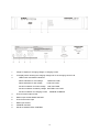
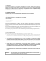
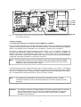
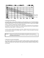
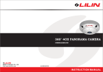
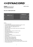
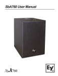
OWNER’S MANUAL
CHARGING UNIT DEM 313
Features
— fully automatic charging unit 24V/4A for constant I/U battery charging in continuous battery power
supply mode
— regulation of charging voltage with high-efficiency primary switched chopper regulator
— charging output with short-circuit and reverse voltage protection
— integrated battery monitoring module with overvoltage protection, exhaustive discharge protection,
mains voltage monitoring, battery voltage monitoring, charging circuit monitoring, LED fault
indicator, collective failure information via floating contact
— integrated 3-digit LC display showing charging voltage and charging current
— temperature tracking of charging voltage in standby mode
— connector BATTERY CONTROL with all control functions and failure indication output
— 19" enclosure with 2HU
IMPORTANT SAFETY INSTRUCTIONS
The lightning flash with arrowhead symbol, within an
equilateral triangle is intended to alert the user to the
presence of uninsulated “dangerous voltage” within the
product’s enclosure that may be of sufficient magnitude to
constitute a risk of electric shock to persons.
The exclamation point within an equilateral triangle is
intended to alert the user to the presence of important
operating and maintance (servicing) instructions in the
literature accompanying the appliance.
1.
2.
3.
4.
5.
6.
7.
8.
9.
10.
Read these instructions.
Keep these instructions.
Heed all warnings.
Follow all instructions.
Do not use this apparatus near water.
Clean only with a damp cloth.
Do not block any of the ventilation openings.
Install in accordance with the manufactures instructions.
Do not install near any heat sources such as radiators, heat registers, stoves, or other apparatus that produce heat.
Only use attachments/accessories specified by the manufacturer.
Refer all servicing to qualified service personnel. Servicing is required when the apparatus has been
damaged in any way, such as power-supply cord or plug is damaged, liquid has been spilled or objects have fallen
into the apparatus, the apparatus has been exposed to rain or moisture, does not operate normally, or has
been dropped.
For US and CANADA only:
Do not defeat the safety purpose of the grounding-type plug. A grounding type plug has two blades and a third grounding prong.
The wide blade or the third prong are provided for your safety. When the provided plug does not fit into your outlet, consult an
electrican for replacement of the absolete outlet.
IMPORTANT SERVICE INSTRUCTIONS
CAUTION: These servicing instructions are for use by qualified personnel only. To reduce the risk of
electric shock, do not perform any servicing other than that contained in the Operating
Instructions unless you are qualified to do so. Refer all servicing to qualified service
personnel.
1. Security regulations as stated in the EN 60065 (VDE 0860 / IEC 65) and the CSA E65 - 94 have to be obeyed when
servicing the appliance.
2. Use of a mains separator transformer is mandatory during maintenance while the appliance is opened, needs to be
operated and is connected to the mains
3. Switch off the power before retrofitting any extensions, changing the mains voltage or the output voltage.
4. The minimum distance between parts carrying mains voltage and any accessible metal piece (metal enclosure),
respectively between the mains poles has to be 3 mm and needs to be minded at all times.
The minimum distance between parts carrying mains voltage and any switches or breakers that are not connected
to the mains (secondary parts) has to be 6 mm and needs to be minded at all times.
5. Replacing special components that are marked in the circuit diagram using the security symbol (Note) is only permissible
when using original parts.
6. Altering the circuitry without prior consent or advice is not legitimate.
7. Any work security regulations that are applicable at the location where the appliance is being serviced have to be strictly
obeyed. This applies also to any regulations about the work place itself.
8. All instructions concerning the handling of MOS - circuits have to be observed.
Note:
SAFETY COMPONENT (HAS TO BE REPLACED WITH ORIGINAL PART ONLY)
14
1
3-digit LC display for charging voltage or charging current
2
LC display switch showing the charging voltage in V or the charging current in A
3
LED function and failure indications:
Failure indication for overvoltage
OVERVOLTAGE
Failure indication for low voltage
LOW VOLTAGE
Function indication for mains voltage
LINE VOLTAGE
Function indication for battery voltage BATTERY VOLTAGE
Function indication for charging current
4.
Fuse for mains output socket
5
Mains output socket MAINS OUTPUT
6
Fuse for the mains input
7
Mains input socket
8
CHARGE OUTPUT
9
Sub-D socket BATTERY CONTROL
CHARGE CURRENT
15
LIST OF CONTENTS
SAFETY INSTRUCTIONS / SERVICE INSTRUCTIONS . . . . . . . . . . . . . . . . . . . . . . . . . . . . . 14
1.
Application . . . . . . . . . . . . . . . . . . . . . . . . . . . . . . . . . . . . . . . . . . . . . . . . . . . . . . . . . . . . 17
2.
Installation instructions . . . . . . . . . . . . . . . . . . . . . . . . . . . . . . . . . . . . . . . . . . . . . . . . . . . 17
3.
Before commissioning . . . . . . . . . . . . . . . . . . . . . . . . . . . . . . . . . . . . . . . . . . . . . . . . . . . 17
3.1
Sub-D socket BATTERY CONTROL . . . . . . . . . . . . . . . . . . . . . . . . . . . . . . . . . . . . . . . . 18
4.
Changing mains voltage . . . . . . . . . . . . . . . . . . . . . . . . . . . . . . . . . . . . . . . . . . . . . . . . . . 18
5.
Battery charging . . . . . . . . . . . . . . . . . . . . . . . . . . . . . . . . . . . . . . . . . . . . . . . . . . . . . . . . 19
5. 1 Charging the batteries in the battery modules DEM 316 or DEM 317 . . . . . . . . . . . . . . . 19
5. 2 Charging other batteries . . . . . . . . . . . . . . . . . . . . . . . . . . . . . . . . . . . . . . . . . . . . . . . . . . 20
6.
Description of function and operation . . . . . . . . . . . . . . . . . . . . . . . . . . . . . . . . . . . . . . . . 20
6.1
OVERVOLTAGE protection . . . . . . . . . . . . . . . . . . . . . . . . . . . . . . . . . . . . . . . . . . . . . . . 21
6.2
LOW VOLTAGE monitoring . . . . . . . . . . . . . . . . . . . . . . . . . . . . . . . . . . . . . . . . . . . . . . . 21
6.3
LINE VOLTAGE monitoring . . . . . . . . . . . . . . . . . . . . . . . . . . . . . . . . . . . . . . . . . . . . . . . 21
6.4
BATTERY VOLTAGE monitoring . . . . . . . . . . . . . . . . . . . . . . . . . . . . . . . . . . . . . . . . . . . 21
6.5
CHARGE CURRENT monitoring . . . . . . . . . . . . . . . . . . . . . . . . . . . . . . . . . . . . . . . . . . . 21
6.6
Protection against reverse voltage and short circuit . . . . . . . . . . . . . . . . . . . . . . . . . . . . . 21
6.7
Collective failure indication . . . . . . . . . . . . . . . . . . . . . . . . . . . . . . . . . . . . . . . . . . . . . . . . 21
6.8
Volt/Ampere meter . . . . . . . . . . . . . . . . . . . . . . . . . . . . . . . . . . . . . . . . . . . . . . . . . . . . . . 22
6.9
Temperature tracking . . . . . . . . . . . . . . . . . . . . . . . . . . . . . . . . . . . . . . . . . . . . . . . . . . . . 22
7.
Fuses . . . . . . . . . . . . . . . . . . . . . . . . . . . . . . . . . . . . . . . . . . . . . . . . . . . . . . . . . . . . . . . . 22
8.
Glossary . . . . . . . . . . . . . . . . . . . . . . . . . . . . . . . . . . . . . . . . . . . . . . . . . . . . . . . . . . . . . . 22
9.
Registrations and standards . . . . . . . . . . . . . . . . . . . . . . . . . . . . . . . . . . . . . . . . . . . . . . 23
10.
Specifications of the charging unit DEM . . . . . . . . . . . . . . . . . . . . . . . . . . . . . . . . . . . . . . 23
16
1. Application
The charging unit DEM 313 was especially designed for fully automatic charging and monitoring of
batteries in the emergency power supplies of alarm devices. In conjunction with the battery modules DEM
316 with 38 Ah or DEM 317 with 65 Ah rated capacity, this combination results in a reliable and failsafe
emergency power source for continuous battery power supply operation. The integrated monitoring
module ensures permanent battery monitoring.
2. Installation instructions
The airflow of the unit must not be blocked. The appliance must be protected against:
- drip or splashwater
- direct sun irradiation
- high ambient temperature or direct influence of heat sources
- high air humidity
- heavy dust deposits
- strong vibrations
lf ihe unit is brought directly from a cold to a warm place, dampness can precipitate on the inner parts.
The unit may only be put into operation after it has warmed up to the ambient temperature (approx. after
one hour).
Should an object or liquid get into the case, disconnect the unit from the current sources immediately and
have the device checked by a DYNACORD service center, before further use.
Do not use any sprays to clean the unit, as these can damage it, perhaps causing it to ignite suddenly.
3. Before commissioning
Before connecting the unit to the mains, the following connections must be made:
•
The D-sub connector socket BATTERY CONTROL (9) of the charging unit ist to be connected with
the D-sub connector BATTERY CONTROL of the battery module (also see Figure 1 and Section 3.1).
•
The CHARGE OUTPUT (8) of the charging unit is to be connected with the charging input CHARGE
CURRENT of the battery module. Please observe correct polarity (see Figure 1). The cross-section
of the line between the charging unit and the battery module must be at least 2.5mm2. Insulated AMP
flat-pin sleeves 6.3x0.8 mm must be used for the connections. The line length must not exceed 2 m.
•
Another device can be connected at the mains connector MAINS OUTPUT (5), if its power
consumption does not exceed 4 A. The mains connector MAINS OUTPUT (5) is protected against
overloading by a fuse (4) with the rating T4A. A fuse rating above T4A is not admissible.
•
lf all connections have been made correctly, the unit can be connected with the mains by means of
the supplied power cable. The mains cable is connected at the 3-pole mains connector socket (7) on
the unit
Attention:
The unit is wired to 2 30V AC by the factory. Switching over to 115 V AC is possible
via wire jumpers inside the unit, (see Section 4).
17
Fig. 1 Connection of the battery to the charging unit
3.1 Control connector BATTERY CONTROL
Various control input/outputs are available at the 15-pole D-sub pin connector BATTERY CONTROL (9):
(Also see Figure 2):
- Input temperature sensor +TEMP/-TEMP
- Output exhaustive discharge relay +LVR/-LVR
- Failure signal output FAILURE
Fig. 2
Connections of the BATTERY CONTROL pin connector
Note The switch rating of the failure signal output amounts to max. 30V dc / 0.IA . The contacts 2, 3
and 13 are provided for test purposes only and must not be used.
4. Alteration of the mains voltage (to be performed by qualified personnel only)
Attention: Before removing the top unit cover, the device must have been disconnected from the
mains for at least 2 minutes, since the capacitors in the device carry hazardous voltage
which needs to discharge first.
For 115V AC operation, the mains powerfuse (6) must be replaced by a fuse 2A slo-blo (T2A). A T2A
label must be stuck over the T1 A marking above the mains power fuse (6). A 115V label must be stuck
over the marking 230V above the mains connector (7). The necessary labels are to be found inside the
unit on the right adjacent to the PCB 85254.
For alteration to 115V AC operation, the wire jumpers S501, S502 and S504 on the PCB 85254 are to be
soldered in and the wire jumper S 503 must be removed, (see Figure 3).
18
F 503
S 504
S 503
S 502
Fig. 3
PCB 85254 Location of the wire jumpers S501 - S504 for altering mains voltage and position
of the output fuse F503
5. Battery charging
5.1 Charging the batteries in the battery modules DEM 316 or DEM 317
Once the charging unit has been connected to the battery module correctly, (see Section 3) and the mains
voltage is present the green LEDs (3) LINE VOLTAGE, BATTERY VOLTAGE and CHARGE CURRENT
light up. The charging current is indicated on the LC display (1), if switch (2) is in position A.
The battery is charged with constant charging current of approx. 4 A. As charging is completed, the
charging current decreases rapidly with rising back-e.m.f. of the battery. At the end of charging, the
charging current falls to a small floating current of approx. 1 mA/Ah of the capacity of the battary to the
loaded, a value which is permanently compatible for the battery. This value can vary with older batteries
in particular, amounting to between 0.5 mA and 10 mA per Ah.
Note:
lf the connection is faulty, there is no charging current and the green LED (3) CHARGE
CURRENT does not light up. Please check all connections between the battery and the
charging unit, all fuses and the mains voltage.
The capacity retention of the battery takes place with a constant voltage of 27.3 V at 20°C. The charging
voltage is indicated by the LC display (1), if swith (2) is in position V. lf the ambient temperature deviates
from +20°C in standby mode, the charging voltage is adapted automatically, depending on the temperature. The temperature coefficient amounts to -40 mV/°C for a 24 V battery.
Note:
The charging unit is designed for the connection to one battery module. A parallel
connection of batteries is not recommended. Batteries connected in parallel cannot be
monitored.
Attention: The charging circuit fuses CHARGE FUSES of the battery modules DEM 315 and DEM
316 must be exchanged for 7.5 A fuses if the charging unit DEM 313 is used. In the
event of a faulty fuse, no charging current flows and the green LED (3) CHARGE
CURRENT does not light up.
19
S 501
- max. value
- rated value
- min. value
5.2 Charging of other batteries
DYNACORD battery modules DEM 316, DEM 317 or other maintenance - free 24V lead-acid batteries
with a rated capacity up to 65 Ah can be charged with the charging unit DEM 313. To do so, the charging
output CHARGE OUTPUT + (8) is to be connected with the plus pole and the charging output CHARGE
OUTPUT - (8) with the negative pole of the battery respectively.
For temperature tracking of Ihe charging voltage in standby mode, the temperature sensor (retrofitting kit
NRS 90200) must be installed according to the retrofitting instructions and is to be connected with the
charging unit (see also Figures 1, 2 and Sections 3.1, 6.9).
In order to prevent exhaustive discharging of the battery, suitable relays must be used which are to be
connected with the charging unit according to Figure 1 or Figure 2. The total coil resistance of the relays
may not be below 70 ohms.
Attention: VDE 0510 is to be observed for the installation of the batteries. Short-circuit-proof
installation of battery cables must be observed in particular, and precautions against the
risk of explosion must be taken.
6. Description of function and operation
The charging unit DEM 313 is designed for constant I/U battery charging in continuous battery power
supply mode. Primary switched circuit technology is used to generate a regulated charging voltage or
charging current which has a high efficiency rate coupled with excellent regulation characteristics and
good reliability.
20
6.1 OVERVOLTAGE protection
This circuit monitors the value of the output voltage of the charging unit. lf the output voltage exceeds the
pre-set upper threshold, the red LED OVERVOLTAGE lights up, the charging unit is disconnected from
battery and consumers automatically, activating the error message. Thereby the battery remains connected to the consumer, supplying it until the failure has been remedied. This proection circuit prevents an
inadmissible increase of the battery voltage and the resultant gassing of Ihe battery with a possible failure
in the charging unit (protection against danger of explosion through detonating gas).
6.2 LOW VOLTAGE monitoring
The battery voltage is monitored in the case of discharge. lf the voltage falls belowthe pre-set threshold
of 22 V, the red LED LOW VOLTAGE lights up. Once the mains voltage is back, the battery is re-charged
automatically. lf the battery voltage does not reach the adjusted threshold of 25.5 V within the given
charging time of approx. 8 h after a mains failure, and the red LED LOW VOLTAGE does not go out this
probably means a battery malfunction and an error message is activated.
6.3 LINE VOLTAGE monitoring
The green LED LINE VO LTAGE goes off in the case of mains failure and an error message is activated.
6.4 BATTERY VOLTAGE monitoring
The battery voltage is monitored with this circuit. lf the battery is alright the green LED BATTERY
VOLTAGE lights up. lf the battery voltage drops below the value of 19.5 V, the battery is discharged, all
LEDs are off, an error message is activaed, the battery is disconnected from all consumers and thus
reliably protected against exhaustive discharging. The exhaustive discharge protection only works with
the battery modules DEM 315, DEM 316 and DEM 317 (also see Sections 5.1 and 5.2).
6.5 CHARGE CURRENT monitoring
This monitors the function of the battery circuit (e.g. cable break or similar). lf the battery charging current
falls below the adjusted value of approx. 10 mA, the green LE D (3) CHARGE CURRENT goes out and
an error message is activated. lf there is no load connected to the battery, the battery charging current
may fall below this limiting value. In such cases it is advisable to connect a resistor of 2200 ohms to the
battery output.
6.6 Reverse voltage and short-circuit protection
Reverse volltage protection prevents damage which may be caused by possible polarisation errors when
the battery is connected to the charging unit. The short-circuit protection disconnects the battery from the
charging unit in the event of shorted cells or total short-circuit. The output fuse F 503 (see Figure 3) in the
charging unit blows in this case and must be replaced by a slo-blo fuse with the rating 4A (T4A). In the
event of a blown fuse, the green LED (3) CHARGE CURRENT goes out and an error message is activated.
6.7 Collective failure signal
The collective failure signal is designed as a floating contact, making available malfunctions of the battery
such as: disconnection at LOW VOLTAGE, wrong polarity or battery short-circuit, as well as malfunctions
of the charging unit such as: absence of LINE VOLTAGE, OVERVOLTAGE or failures in the charging
circuit CHARGE CURRENT for long-range transmission. The corresponding failure is indicated on the
unit itself via the corresponding LED (3) lighting up or going off respectively,(see page 2 as well as Section
6.1 to 6.6). The floating contact of the collective failure indication is wired at the D-sub pin connector
BATTERY CONTROL (9) (see Figure 2).
21
6.8 Volt-/Amperemeter
A 3-digit LC display (1) with toggle switch (2) is provided for measurement of the battery voltage or the
charging current. With the switch V/A at the front panel in position V, the battery vollage is shown. Likewise
the charging current is shown with the switch in position A.
6.9 Temperature tracking
The charging voltage requires battery-adapted temperature tracking in conjunction with operation under
ambient temperatures between +5°C .. +40°C. The temperature is to be measured in direct proximity to
the battery. The temperature tracking feature consists of a temperature sensor, integrated in the battery
module DEM 316 or DEM 317 which must be installed in direct proximity to the battery, and a control
circuit in the charging unit. The sensor is connected to the charging unit via the 15-pole pin connector
BATTERY CONTROL. The control circuitis activated if the temperature sensor has been connected
correctly. lf the connection of the temperature sensor is faulty of there is a short-circuit or a break of the
sensor lines or of the sensor, this interupts battery charging and the collective failure signal is activated.
The retrofitting kit NRS 90200 is to be used for the battery module DEM 315 or other batteries and is
available as Article no. 121 950.
7. Fuses
The dimensions of all the fuses in the unit are 5 x 20 mm and must correspond with IEC 127.
Fuse holder (4)
Fuse holder (6)
Fuse holder (6)
PCB 85254, F503
mains power fuse for mains connector (see page 2)
mains power fuse for 230V ac (see page 2)
mains power fuse for 11 5V ac (see page 2)
output fuse CHARGE OUTPUT (see Figure 3)
T4A 250V
T1A 250V
T2A 250V
T4A 250V
8. Glossary:
- Continuous battery power supply (standby operation)
In this mode, the battery is constantly kept at full charge. It only gives off current if the DC source supplied
by the mains fails.
- Nominal capacity:
The nominal capacity is the value in ampere-hours for a 20-hour even, uninterrupted discharge with up
to the cutoff voltage of 1.75 V/cell at a temperature of 22°C.
- Capacity:
The capacity of a battery is the amount of electricity which can be extracted under the condlitions in
question. This depends on the discharge current, the cut-off voltage and the temperature.
- Service life
For batteries in alarm apparatus and emergency announcement systems, the end of a battery’s service
life (limited duration of operation) is reached when the capacity is less than 80% of the rated capacity.
- Stored energy time
This is the time-span between recognition of a failure in the mains supply and remedying of this failure.
- Alarm duration
The alarm duration is the time-span during which the alarm signal is given out.
- Emergency announcement duration
This is the time during which announcements are made to clear the building or section of a building.
22
9. Approvals and standards
- The charging units correspond to the following standards:
EN 55014-2
Immunity requirements for household appliances, electric tools and similar electrical
appliances
EN 50082-1
Basic standard for interference rejection; living area, business areas as well as small
enterprises
EN 60065
Safety requirements for mains-operated electronic appliances and related accessories
for house hold use and similar general application
EN 60742
Regulations for isolation transformers and safety transformers
10. Specifications DEM 313
Mains voltage
internally solderable to
Safety class
Rated output voltage
Voltage adjustment for
battery charging 2.275 V/cell
Tolerance of the output voltage at 20°C
Temperature coefficient of the charging voltage
Ripple at nominal operation
Static mains control
at input deviations of +l 0% -15 %
Nominal charging current
Current limitation
Standby current at power failure
Switching frequency
Efficiency
Failure detection OVERVOLTAGE
Failure detection at battery LOW VOLTAGE
Failure detection at battery LOW VOLTAGE
Failure detection at mains low voltage LINE VOLTAGE
Failure detection at mains low voltage LINE VOLTAGE
Switch-off at BATTERY VOLTAGE
Failure detection at CHARGE CURRENT
Operating temperature range
Storage temperature
Dimensions W x H x D
Mounting depth without connectors
Mounting depth with connectorsmax.
Weight
≤ 0.05%
4A
approx. 4 A
110 mA
88 kHz ±l0%
approx. 83 %
≥ 29.6 V
≤ 25.5 V operation mode charging
≤ 22.0 V operation mode discharging
165 V ±15% for 230 V ac operation
83.5 V ±15% for 115 V ac operation
≤ 19.5 V
≤ 20 rrA
+5″C + 40″C
-40″C+ 70″C
483 x 88 x 335 mm
300 mm
350 mm
4.4 kg
Retrofitting kit for DEM 313:
NRS 90200 temperature sensor
Art.No
121950
23
230 V +10%/-15 % 50-60 Hz
115 V +10%/-15 % 50-60 Hz
I
24 V
27.3 V
± 0.37 %
-40 mV/°C
≤ 0.1%