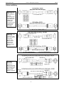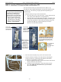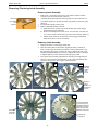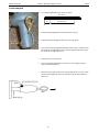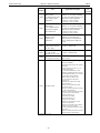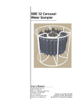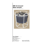
1
User Manual Release Date: 02/11/2015 Manual version Firmware version Software versions • • • • SBE 32 Carousel Water Sampler 022 1.0b & later SeatermAF 2.14 & later Seasave V7 7.23.2 & later Limited Liability Statement Extreme care should be exercised when using or servicing this equipment. It should be used or serviced only by personnel with knowledge of and training in the use and maintenance of oceanographic electronic equipment. SEA-BIRD ELECTRONICS, INC. disclaims all product liability risks arising from the use or servicing of this system. SEA-BIRD ELECTRONICS, INC. has no way of controlling the use of this equipment or of choosing the personnel to operate it, and therefore cannot take steps to comply with laws pertaining to product liability, including laws which impose a duty to warn the user of any dangers involved in operating this equipment. Therefore, acceptance of this system by the customer shall be conclusively deemed to include a covenant by the customer to defend, indemnify, and hold SEA-BIRD ELECTRONICS, INC. harmless from all product liability claims arising from the use or servicing of this system. 2 Manual revision 022 Declaration of Conformity Declaration of Conformity 3 SBE 32 Manual revision 022 Table of Contents SBE 32 Table of Contents Limited Liability Statement ................................................................ 2 Declaration of Conformity .................................................................. 3 Table of Contents ................................................................................. 4 Section 1: Introduction ........................................................................ 6 About this Manual .............................................................................................6 Unpacking Carousel ...........................................................................................6 Section 2: Description of Carousel ..................................................... 7 System Description ............................................................................................7 Specifications .....................................................................................................8 Dimensions and Weights ...................................................................................9 End Cap Connectors ........................................................................................10 Cables and Wiring ...........................................................................................11 System Configurations .....................................................................................12 Real-Time Data Acquisition and Control .................................................12 Autonomous Data Acquisition and Control (no conducting wire required)...................................................................14 Section 3: Preparing Carousel for Deployment............................... 15 Assembling SBE 32 .........................................................................................15 12-Bottle Full-Size SBE 32 ......................................................................15 24-Bottle Full-Size SBE 32 ......................................................................18 SBE 32 - Installing CTD Extension Stand and Mounting CTD.......................20 SBE 32C and 32SC - Mounting CTD ..............................................................21 Mounting Bottles to Carousel ..........................................................................22 Rigging and Cocking Lanyards........................................................................23 Lanyard Tension Under 25 kg (55 lbs) .....................................................23 Lanyard Tension Between 25 and 50 kg (55 and 110 lbs) ........................25 Section 4: Deploying and Operating Carousel ................................ 26 Optimizing Data Quality ..................................................................................26 Taking Water Samples on Upcast .............................................................26 Holding Water Sampler Stationary before Taking Samples .....................26 Taking Samples in Well-Mixed Water to Check for Drift ........................27 Using Real-Time Control for Highest Quality Water Samples.................27 Software Installation ........................................................................................27 Communications and Commands ....................................................................28 System Setup and Operation ............................................................................29 SBE 11plus Deck Unit ..............................................................................30 SBE 33 Deck Unit ....................................................................................31 SBE 17plus V2 Searam.............................................................................32 Auto Fire Module (AFM) .........................................................................33 Recovery ..........................................................................................................34 Processing Data................................................................................................35 Section 5: Routine Maintenance ....................................................... 36 Corrosion Precautions / Cleaning ....................................................................36 Connector Mating and Maintenance ................................................................37 Bottle Maintenance ..........................................................................................37 Storage .............................................................................................................37 Removing / Replacing Latch Assembly...........................................................38 Removing Center Pylon ...................................................................................39 O-Ring Maintenance ........................................................................................39 Repairing Frame Coating .................................................................................40 4 Manual revision 022 Table of Contents SBE 32 Glossary .............................................................................................. 41 Safety and Electrical Symbols .........................................................................42 Appendix I: Making and Rigging Lanyards.................................... 43 Lower Lanyard .................................................................................................44 Upper Lanyard .................................................................................................45 Middle Lanyard................................................................................................46 Reversing Thermometer Lanyard ....................................................................47 Appendix II: CTD Plumbing ............................................................ 48 Horizontal Mount .............................................................................................48 Vertical Mount .................................................................................................50 Appendix III: Electronics Disassembly/Reassembly....................... 52 At Latch End Cap (main Carousel electronics) ................................................52 At Connector End Cap (additional electronics for serial interface) .................54 Appendix IV: Never-Seez Blue Moly Data Sheet ........................... 55 Appendix V: Replacement Parts ...................................................... 57 Appendix VI: Manual Revision History .......................................... 61 Index .................................................................................................... 63 5 Manual revision 022 Section 1: Introduction SBE 32 Section 1: Introduction This section includes a description of the scope of this manual, and a list of what is included with a typical Carousel shipment. About this Manual This manual is to be used with the SBE 32 Carousel Water Sampler. It is organized to guide the user in preparing the Carousel for operation. We’ve included an overview of system operation, detailed specifications, installation instructions, maintenance information, command descriptions, and helpful notes throughout the manual. Depending on which CTD is used with the system, the Carousel can be operated and controlled by: • SBE 11plus Deck Unit, • SBE 33 Carousel Deck Unit, • SBE 17plus V2 Searam, or • Auto Fire Module (AFM) See the appropriate manual for details on operating the Carousel. Sea-Bird welcomes suggestions for new features and enhancements of our products and/or documentation. Please contact us with any comments or suggestions ([email protected] or 425-643-9866). Our business hours are Monday through Friday, 0800 to 1700 Pacific Standard Time (1600 to 0100 Universal Time) in winter and 0800 to 1700 Pacific Daylight Time (1500 to 0000 Universal Time) the rest of the year. Unpacking Carousel A typical Carousel shipment includes: Notes: • The SBE 32C (compact model) and 32SC (sub-compact model) are shipped from Sea-Bird with the mechanical / electrical assembly fully assembled. • When feasible, full-size SBE 32s are shipped from Sea-Bird with the mechanical / electrical assembly fully assembled (feasibility depends on shipping size limitations for particular destination). However, some full-size SBE 32s must be assembled by the user, as described in Section 3: Preparing Carousel for Deployment. • Mechanical /electrical assembly Guard frame assembly: upper and lower guard rings, side bars (not applicable to 32SC), and CTD extension stand Upper and lower adapter plates Hub and pylon, including electronics and latch assembly Lifting bail Associated hardware • Cables - number and type is dependent on which CTD and controller is to be used with the Carousel • Software, and electronic copies of this user manual and software manuals on CD-ROM • Spare parts kit 6 Manual revision 022 Section 2: Description of Carousel SBE 32 Section 2: Description of Carousel This section describes the functions and features of the SBE 32 Carousel, specifications, dimensions, end cap connectors, and system configuration. System Description Latch with plastic side bars (typical) Latch with titanium side bars The SBE 32 Carousel Water Sampler is a versatile, reliable, continuously operating water sampling system. Each bottle position has its own lanyard release latch controlled by a magnetic trigger. When the microprocessor in the Carousel pylon receives a command to fire a bottle, it activates the magnetic trigger for the bottle position specified. Bottles may be fired sequentially or any order. The Carousel’s unique design allows the lanyard release mechanism to be cocked with a touch of a finger before the lanyards are secured, permitting fast, convenient, safe, and reliable setup. Titanium, acetal plastic, and other corrosion-resistant materials are used in the latch and magnet assembly. The latch array’s modular construction makes servicing easy. The latches are available with plastic side bars, or titanium side bars for more demanding applications. The energy used to trip the magnetic trigger that controls each release latch is stored in an internal capacitor. When a fire command is received, the Carousel switches the capacitor to the selected trigger for 15 milliseconds. A fireconfirm circuit detects current flowing. Receipt of a fire-confirm message from the Carousel verifies the bottle position selected and that energy was delivered to the magnetic trigger. The capacitor is charged to 75 volts with a current-limited DC/DC converter; the capacitor recharge time is approximately 3 seconds. The Carousel electronics are electrically isolated from the CTD. The Carousel is available in 12-, 24-, and 36-bottle configurations. It accepts standard water sample bottles ranging from 1.2 to 30 liters (specified at time of purchase). Typically, a Carousel built for bottles of one size accommodates bottles of all smaller sizes (exceptions: a full-size Carousel built for 5-liter bottles does not accommodate 2.5-liter bottles; a full-size Carousel built for 1.7-liter bottles does not accommodate 1.2-liter bottles). The aluminum electronics housing is rated to a depth of 6800 meters. Titanium pressure housings have depth ratings to 7000 or 10,500 meters. The SBE 32 Carousel is available in three sizes: • Full-Size Carousel (SBE 32) The full-size Carousel is optimized for use with the SBE 9plus CTD, but can also be used with the SBE 19 / 19plus /19plus V2 or 25 / 25plus CTD, SBE 49 CTD (real-time use only), or Neil Brown Mk III CTD. The SBE 32 holds 12, 24, or 36 bottles, ranging in size from 1.2 to 30 liters. • Compact Carousel (SBE 32C) The SBE 32C has reduced height and slightly smaller diameter, for use where vertical clearance is limited, and can be used with the SBE 9plus, 19 / 19plus / 19plus V2, or 25 / 25plus CTD, or SBE 49 CTD (real-time use only). The SBE 32C holds 12 bottles, ranging in size from 1.2 to 8 liters. • Subcompact Carousel (SBE 32SC) The SBE 32SC offers a small system, optimized for use with the SBE 19 / 19plus /19plus V2 or 25 / 25plus CTD, or SBE 49 CTD (real-time use only). The SBE 32SC holds 12 bottles, 1.7 or 2.5 liters. 7 Manual revision 022 Section 2: Description of Carousel SBE 32 Carousels can be controlled in several ways: CTD Operation Carousel Size Real-Time Control 32, 32C SBE 9plus SBE 11plus Deck Unit 32, 32C, 32SC SBE 19 / 19plus / 19plus V2 / 25 / 25plus / 49 SBE 33 Deck Unit 32 Neil Brown Mk III SBE 33 Deck Unit 32, 32C, 32SC None SBE 33 Deck Unit 32, 32C SBE 9plus SBE 17plus V2 Searam SBE 19 / 19plus / 19plus V2 / 25 / Autonomous 32, 32C, 32SC (no conducting 25plus CTD or SBE 50 Pressure Sensor wire required) 32, 32C, 32SC None Auto Fire Module (AFM) Auto Fire Module (AFM) Each of these combinations is described in more detail in System Configurations below. Notes: • Help files provide detailed information on the software. • Separate software manuals on CDROM contain detailed information on Seasave and SBE Data Processing. • Sea-Bird supplies the current version of our software when you purchase an instrument. As software revisions occur, we post the revised software on our website. See our website for the latest software version number, a description of the software changes, and instructions for downloading the software. Sea-Bird equipment is supplied with a powerful Windows software package, Seasoft V2, which includes: • • • • Seaterm – terminal program for easy communication and data retrieval. SeatermAF V2 – terminal program for easy communication and data retrieval for a system that includes an Auto Fire Module (AFM) or SBE 17plus V2 Searam; referred to as SeatermAF for brevity. Seasave V7 – program for acquiring, converting, and displaying real-time or archived raw data. SBE Data Processing - program for calculation and plotting of conductivity, temperature, pressure, auxiliary sensor data, and derived variables such as salinity and sound velocity. Specifications External power requirement (maximum): 12 - 15VDC, 0.25A Sea cable power requirement (maximum): 70VDC – 250VDC, 90W Current when charging capacitor: 205 milliamps (for approximately 35 seconds on power-up and 3 seconds to recharge after each bottle firing) Current when not charging capacitor: 110 milliamps 6800 meters (aluminum housing), 7000 or 10500 meters (titanium housing) Frame: painted aluminum Latch/magnet assembly: titanium, acetal plastic, and other corrosion-resistant materials Housing (for electrical and release assembly and mount hub): aluminum or titanium Power Depth Rating Materials 8 Manual revision 022 Section 2: Description of Carousel SBE 32 Dimensions and Weights Bottle Mount Stand Carousel Height, mm (inches) Diameter, mm (inches) CTD Extension Stand Height, mm (inches) Diameter, mm (inches) Total Package Height, mm (inches) 1 Weight, kg (lbs) Full-Size (SBE 32) 12 bottle, 1.2 liter 2 See 2.5 liter 12 bottle, 1.7 liter 2 788 (31.0) 1201 (47.3) 68 (150) 12 bottle, 2.5 liter 2 1024 (40.3) 1438 (56.6) 79 (174) 1234 (48.6) 78 (172) 12 bottle, 5 liter 2 12 bottle, 8 liter 2 820 (32.3) See 2.5 liter 991 (39.0) 406 (16.0) 991 (39.0) 1024 (40.3) 1438 (56.6) 79 (174) 12 bottle, 10 liter 2 1189 (46.8) 1603 (63.1) 82 (182) 12 bottle, 12 liter 2 1316 (51.8) 1730 (68.1) 83 (184) 12 bottle, 20 liter 3 1072 (42.2) 12 bottle, 30 liter 3 1351 (53.2) 24 bottle, 1.2 liter 2 See 2.5 liter 24 bottle, 1.7 liter 2 800 (31.5) 24 bottle, 2.5 liter 2 24 bottle, 5 liter 3 24 bottle, 8 liter 3 1550 (61.0) 427 (16.8) 1549 (61.0) 1506 (59.3) 185 (410) 1786 (70.3) 199 (440) See 2.5 liter 1143 (45.0) 406 (16.0) 1143 (45.0) 1214 (47.8) 95 (210) 1003 (39.5) 1417 (55.8) 106 (235) 869 (34.2) 1300 (51.3) 179 (397) 1506 (59.3) 185 (410) 1659 (65.3) 194 (430) 1786 (70.3) 199 (440) 1072 (42.2) 24 bottle, 10 liter 3 1224 (48.2) 24 bottle, 12 liter 3 1351 (53.2) 1550 (61.0) 427 (16.8) 1549 (61.0) Compact (SBE 32C) 12 bottle, 1.2 - 8 liter 2 965 (38.0) 966 (38.0) - 973 (38.3) 68 (150) 699 (27.5) - 1003 (39.5) 52 (114) Subcompact (SBE 32SC) 12 bottle, 2.5 liter 1 2 991 (39.0) Total Package: Total package height = bottle mount stand + CTD extension stand (if applicable) + height of lifting bail above bottle mount stand Total package height does not include optional Deck Pads. Total package weight does not include bottles or CTD. 2 Frame parts are 25.4 mm (1 inch) diameter for: Full-size SBE 32 12-bottle through 12-liter bottle size, Full-size SBE 32 24-bottle through 2.5-liter bottle size, Compact SBE 32C, and • Sub-compact SBE 32SC all sizes. • • • 3 Frame parts are 34.9 mm (1.375 inch) diameter for: Full-size SBE 32 12-bottle larger than 12-liter bottle size, and • Full-size SBE 32 24-bottle larger than 2.5-liter bottle size. • Full-Size Carousel (shown with SBE 9plus; mounting for other CTDs is similar) 9 Manual revision 022 Section 2: Description of Carousel SBE 32 End Cap Connectors = Impulse glass-reinforced epoxy connectors: 2-pin XSG-2-BCL-HP-SS, 4-pin XSG-4-BCL-HP-SS, and 6-pin AG-306-HP-SS as applicable. End cap connectors are located at the bottom of the pylon / hub assembly. Modem Interface Only = MCBH (wet-pluggable) connectors (all with 3/8” length base, ½-20 thread) 2-pin MCBH-2MP (WB), 4-pin MCBH-4MP (WB), or 6-pin MCBH-6MP (WB) as applicable. Note: Wet-pluggable connectors are available in anodized aluminum or titanium; connector type must match Carousel housing (aluminum or titanium). Modem Interface and Serial Interface 10 Manual revision 022 Section 2: Description of Carousel Cables and Wiring SBE 9plus/17plus cable – SBE 32 6-pin connector to 9plus JT7 connector (for realtime sampling with 11plus Deck Unit) or SBE 17plus Searam 6-pin Carousel connector (for autonomous sampling with 9plus CTD) AFM Cable – from SBE 32 JB2 connector to AFM JB2 connector (for autonomous sampling with SBE 19, 19plus, 19plus V2, 25, 25plus CTD or SBE 50 pressure sensor) Test Cable SBE 32 JB1 connector to SBE 33 Sea Cable connector (for realtime sampling with SBE 19, 19plus, 19plus V2, 25, 25plus, or 49 CTD) 11 SBE 32 Manual revision 022 Section 2: Description of Carousel SBE 32 Seacable Extension cable – Connects to SBE 32 JB1 connector, for connection to seacable or test cable (for realtime sampling with SBE 19, 19plus, 19plus V2, 25, 25plus, or 49 CTD) System Configurations Notes: • For real-time operation, connection to two COM ports on the computer is required. COM1 (CTD data channel) and COM2 (Carousel command channel) are the defaults, and are shown in the diagrams for illustration only. You can use any two ports, in any order; set up the COM port configuration in Seasave to correspond. • Seasave also supports acquisition of data from a NMEA device connected directly to the computer (instead of the deck unit). Real-Time Data Acquisition and Control • SBE 11plus Deck Unit The Carousel is designed to be connected to the SBE 9plus CTD and powered and controlled via the SBE 911plus modem channel. Bottles may be closed using the push-buttons on the SBE 11plus, or via the RS-232C modem connector on the back of the 11plus while acquiring real-time data with Seasave. The 11plus includes a NMEA Interface to support NMEA 0183 protocol, and an interface for a Surface PAR sensor. 12 Manual revision 022 Notes: • For real-time operation, connection to two COM ports on the computer is required. COM1 (CTD data channel) and COM2 (Carousel command channel) are the defaults, and are shown in the diagrams for illustration only. You can use any two ports, in any order; set up the COM port configuration in Seasave to correspond • Seasave also supports acquisition of data from a NMEA device connected directly to the computer (instead of the deck unit). • SBE 33’s Surface PAR interface was optional prior to 2012. Section 2: Description of Carousel • SBE 32 SBE 33 Carousel Deck Unit – With a serial interface, the Carousel can be powered and controlled using the SBE 33, and can be used with or without a CTD (SBE 19/19plus/19plus V2, 25/25plus, or 49 CTD). The interface provides real-time data telemetry capability and surface power for these CTDs, and permits the control of the Carousel through the SBE 33 or via Seasave. When used without a CTD, bottles are closed with the SBE 33 front panel controls; depth determination must be approximated by monitoring the cable payout. The SBE 33 has a NMEA Interface to support NMEA 0183 protocol, and an interface for a Surface PAR sensor. An optional interface in the SBE 32 and 33 is also available for a Neil Brown Mk III CTD. This option allows the Carousel to provide the compliant supply voltage to the Mk III, and extra power for fluorometers and other sensors not easily supported by the Mk III. NMEA and Surface PAR capabilities in the SBE 33 are not available for this setup. 13 Manual revision 022 Section 2: Description of Carousel SBE 32 Autonomous Data Acquisition and Control (no conducting wire required) • SBE 17plus V2 Searam The Searam, mounted with the SBE 9plus CTD, allows the Carousel to operate autonomously on non-conducting cables. Using pressure data from the SBE 9plus and a programmable table of bottle closure pressures, the Searam signals the Carousel to close bottles on upcast. Built-in logic and user-input parameters provide control in determining when the upcast begins, preventing accidental bottle closure caused by temporary upward movements during downcast. Power is supplied to both the SBE 9plus and the Carousel by the Searam’s batteries, and data from the SBE 9plus is stored in the Searam memory. • Auto Fire Module (AFM) The AFM, mounted on or near the Carousel, allows the Carousel to operate autonomously on non-conducting cables, with or without a CTD. Used without a CTD, the AFM is programmed to fire bottles at predefined intervals of elapsed time. The point at which samples are taken is determined (approximately) by monitoring cable payout and elapsed time. Used with an SBE 19/19plus/19plus V2 or 25/25plus CTD or SBE 50 Pressure Sensor, the AFM monitors the pressure data recorded by the CTD (or transmitted by the SBE 50) in real-time, and fires bottles at predefined pressures (depths) on upcast or downcast, or whenever the system is stationary for a specified period of time. Power is supplied to the Carousel by the AFM’s batteries; bottle number, firing confirmation, and five scans of CTD data are recorded in AFM memory for each bottle fired. 14 Manual revision 022 Section 3: Preparing Carousel for Deployment SBE 32 Section 3: Preparing Carousel for Deployment This section covers: • Assembling the Carousel • Installing the extension stand • Mounting the instrument to the Carousel • Mounting bottles to the Carousel • Rigging and cocking lanyards Assembling SBE 32 Note: Place a small quantity of NeverSeez Blue Moly compound (provided) on all screws, to prevent seizing. Lower adapter plate 2” x 4” boards, or similar Lower guard ring The SBE 32C (compact model) and 32SC (sub-compact model) are shipped from Sea-Bird fully assembled. The assembly instructions apply only to the full-size SBE 32. When feasible, full-size SBE 32s are shipped from Sea-Bird fully assembled (feasibility depends on shipping size limitations for particular destination). However, some full-size SBE 32s must be assembled by the user, as described below. Parts and assembly procedure vary, depending on the number of bottles. Instructions follow for: • 12-bottle SBE 32 • 24-bottle SBE 32 12-Bottle Full-Size SBE 32 1. Place the lower guard ring on a flat surface on two boards. The boards lift the assembly for easy installation of the guard side bars (Step 7). 2. Set the lower adapter plate (adapter plate with bottle locator pins on its top surface) on the flange of the lower guard ring, aligning the mounting holes. 3. The pylon/hub assembly is shipped as an assembly; six socket head cap screws, lock washers, and flat washers retain the pylon in the hub. The lifting bail is shipped installed on the pylon/hub assembly, to show the arrangement of hardware. Remove the lifting bail and associated hardware from the pylon/hub assembly for now, noting the arrangement of the lifting bail hardware for later reinstallation. Remove lifting bail Pylon / hub assembly Pylon / hub assembly 15 Manual revision 022 Section 3: Preparing Carousel for Deployment 4. Pylon / hub assembly SBE 32 Set the pylon/hub assembly on the lower adapter plate, aligning the mounting holes. Secure the pylon/hub assembly and lower adapter plate to the lower guard ring through the four 1/2” holes (the two oversized holes will be used for the lifting bail later). Use four 1/2-13 x 3 1/2” socket head cap screws, 1/2” flat washers, 1/2” flat washers, 1/2” split lock washers, and 1 /2-13 hex nuts. Do not tighten completely. Pylon / hub assembly Lower adapter plate Upper adapter plate Upper guard ring 5. Set the upper adapter plate (adapter plate with holes to secure water bottles to Carousel) on the pylon/hub assembly, aligning the mounting holes. 6. Set the upper guard ring on the upper adapter plate, aligning the mounting holes. Secure the upper guard ring to the upper adapter plate and pylon/hub assembly through the four 1/2” holes (the two oversized holes will be used for the lifting bail later). Use four 1/2-13 x 3 1/2” socket head cap screws, 1/2” flat washers, 1/2” flat washers, 1/2” split lock washers, and 1 /2-13 hex nuts. Do not tighten completely. 7. Place the six guard side bars between the upper and lower guard rings. Note that there are two types of side bars: one for upper guard ring positions without a riser bar (1), and the other for positions with a riser bar (2). A. Connect the side bars to the upper guard ring, loosely installing the 1 /4-20 x 11/2” flat head socket cap screws. B. Connect the side bars to the lower guard ring, installing the 1 /4-20 x 11/2” flat head socket cap screws. Tighten these screws fully. C. Fully tighten the screws connecting the side bars and upper guard ring. Pylon / hub assembly 1 2 Guard side bars Riser bar Side bar (1) Side bar (2) 16 Manual revision 022 Section 3: Preparing Carousel for Deployment 8. Insulator SBE 32 Install the lifting bail: A. Install the plastic insulators: two longer insulators in the upper guard ring / upper adapter plate / pylon/hub assembly; two shorter insulators in the hub assembly / lower adapter plate / lower guard ring. B. Slide the lifting bail legs through the upper insulators. C. Before inserting into the lower insulators, place a 1/2” nut on each leg of the lifting bail and thread the nuts to within 1” of the end of the threads. Place a 1/2” flat washer on each leg, and then insert the bail legs into the lower insulators. Slide the bail into place until the stops above the upper insulators seat. D. Install the final two shorter insulators over the ends of the bail legs and into the bottom of the lower guard ring. E. Secure the bail leg to the lower guard ring with the 1/2” nuts, split lock washers, and flat washers. F. Tighten the nuts above the lower guard ring connection until they seat on the insulators. Longer 1 Stop /2” nut and washer Slide bail through upper insulators 9. Fully tighten all hardware installed in Steps 1 through 8. Make sure that all threads are protected with Never Seez Blue Moly. 17 Manual revision 022 Lower guard ring Section 3: Preparing Carousel for Deployment 2” x 4” boards, or similar Lower guard ring Note: The lifting bail, shown in the photo, is not installed until Step 10. 24-Bottle Full-Size SBE 32 1. Place the lower guard ring on a flat surface on two boards. The boards lift the assembly for easy installation of the guard side bars (Step 7). 2. Set the lower adapter plate (adapter plate with bottle locator pins on its top surface) on the flange of the lower guard ring, aligning the mounting holes. Secure the adapter plate to the guard ring through six 1/2” holes (every other hole in the adapter plate outer circle; see photo and illustration at bottom of page), using 1/2-13 x 3 1/2” socket head cap screws, 1/2” flat washers, 1/2” flat washers, 1/2” split lock washers, and 1 /2-13 hex nuts. Do not tighten completely. 3. Set the pylon/hub assembly on the lower adapter plate, aligning the mounting holes. Secure the pylon/hub assembly to the lower adapter plate through the six 1/2” holes in the adapter plate inner circle, using 1 /2-13 x 2 1/2” socket head cap screws, 1/2” flat washers, 1/2” flat washers, 1 /2” split lock washers, and 1/2-13 hex nuts. Do not tighten completely. 4. Install the four rods: A. The rods are shipped with hardware installed, to show the hardware arrangement. The bottom end of the rod has a lock nut, flat washer, flat washer, lock washer, and nut. The nut should be approximately 10 cm (4 inches) from the end of the rod. Remove the lock nut and flat washer from the bottom of the rod. B. Insert the rod through the lower adapter plate and lower guard ring until the flat washer, lock washer, and nut rest on the adapter plate. Secure the rod by installing the flat washer and lock nut on the underside of the lower guard ring. C. Remove the remaining flat washer and lock nut from the top end of the rod. 5. Slide the upper adapter plate through the rods until it rests on the pylon/hub assembly. Secure the adapter plate to the pylon/hub assembly through the six countersunk 1/2” holes, using 1/2-13 x 2 1/2” socket head cap screws, 1/2” flat washers, and 1/2-13 lock nuts. 6. Slide the upper guard ring through the rods until it rests on the upper adapter plate. Install the four 1/2-13 lock nuts and 1/2” flat washers on the rods. Upper guard ring ½-13 lock nut and ½ “ flat washer Upper adapter plate Bail leg (2) Pylon/hub assembly Lower adapter plate Rod (4) SBE 32 Lower guard ring 18 Manual revision 022 Section 3: Preparing Carousel for Deployment 7. 1 2 Guard side bars Side bar (2) Longer Lifting bail Riser bar SBE 32 Place the six guard side bars between the upper and lower guard rings. Note that there are two types of side bars: one for upper guard ring positions without a riser bar (1), and the other for positions with a riser bar (2). A. Connect the side bars to the upper guard ring, loosely installing the 3 /8-16 x 2” flat head socket cap screws. B. Connect the side bars to the lower guard ring, installing the 3 /8-16 x 2” flat head socket cap screws. Tighten these screws fully. C. Fully tighten the screws connecting the side bars and upper guard ring. Side bar (1) 8. The lifting bail is shipped with the hardware installed on it, to show the hardware arrangement. Remove the hardware for now, noting the hardware arrangement for reinstallation. 9. Install the lifting bail: A. Install the plastic insulators: two longer insulators in the upper guard ring; two shorter insulators in the lower adapter plate. B. Place the 3/4” flat washers on the upper insulators. C. Slide the lifting bail through the flat washers and upper insulators. D. Before inserting into the lower insulators, place a 3/4” nut on each leg of the lifting bail and thread the nuts to within 2.5 cm (1 inch) of the end of the threads. Place a 3/4” flat washer on each leg, and then insert the bail legs into the lower insulators. Slide the bail into place until the stops above the upper insulators seat. E. Install the final two shorter insulators over the ends of the bail legs and into the bottom of the lower guard ring. F. Secure the bail leg to the lower guard ring with the 3/4” nuts, split lock washers, and flat washers. G. Tighten the nuts above the lower adapter plate until they seat on the insulators. Stop 10. Fully tighten all hardware installed in Steps 1 through 9. Make sure that all threads are protected with Never Seez Blue Moly. 19 Manual revision 022 Section 3: Preparing Carousel for Deployment SBE 32 SBE 32 - Installing CTD Extension Stand and Mounting CTD Note: The typical ring top cage (PN 801269 or 801270) for an SBE 19plus or 19plus V2 does not fit inside the extension stand. For use with these instruments in the extension stand: • 19plus or 19plus V2 with strain gauge pressure - Order a shorter cage with a flat top, PN 50396. • 19plus or 19plus V2 with Quartz pressure – contact Sea-Bird. Flat top cage type mounts to CTD extension stand with 50199 The CTD extension stand is provided with the full-size SBE 32 only. Note that the CTD is mounted horizontally in its cage in the extension stand; see Appendix II: CTD Plumbing for pump placement and plumbing for a horizontal mount. 1. Mount the CTD (in its cage) in the extension stand. • For CTDs with a flat top cage (most cages) – Follow instructions that come with PN 50199 SBE 9plus Carousel Mount Kit. • For CTDs with a ring top cage (some older cages) – Install PN 50124 CTD Cage to Extension Stand Mounting Adapter Kit on the ring top to reduce the ring diameter. Then, follow the instructions that come with PN 50199 SBE 9plus Carousel Mount Kit, but omit the PN 23687 and 23688 mount insulators. Insulator bushing Ring top cage requires 50124 adapter kit in addition to 50199 to mount to CTD extension stand Ring insulator 50124 Adapter Kit for Ring Top Cage Sandwich ring top between retainer ring and ring insulator; secure with screws. Insert insulator bushing through hole in retainer ring. Note: Plumbing for vertical configuration shown; see Appendix II: CTD Plumbing for pump placement and plumbing for a horizontal mount before installing in extension stand. Carousel frame U-bolt (place Teflon tape over bars before installing) Retainer ring 50124 Adapter Kit assembled Note: Cage ring top not shown. 2. Place the Carousel assembly on top of the CTD extension stand. 3. Secure the Carousel assembly to the CTD extension stand using the U-bolts (4 U-bolts for 39-inch and 45-inch diameter stand frames; 6 U-bolts for 61-inch diameter stand frames). A. Wrap the supplied Teflon tape over the Carousel frame and extension stand at each of the U-bolt locations. B. Install the U-bolts and hardware (1 flat washer and 2 lock nuts per U-bolt). Make sure that all threads are protected with Never Seez Blue Moly. CTD extension stand Note: CTD and CTD cage not shown 20 Manual revision 022 Section 3: Preparing Carousel for Deployment SBE 32 SBE 32C and 32SC - Mounting CTD See Appendix II: CTD Plumbing for pump placement and plumbing for a horizontal or vertical mounting. To provide room for mounting a CTD and accessories, the bottle positions in the SBE 32C and 32SC are closely spaced into two arcs, the centers of which are 180 degrees apart. This leaves four auxiliary mounting positions between the ends of the arcs for mounting a CTD and accessories. • SBE 19, 19plus, 19plusV2, 25, or 25plus The SBE 19, 19plus, or 19plus V2 mounts vertically in one of the auxiliary mounting positions, using an accessory mounting fixture. Similarly, the SBE 25 or 25plus main housing mounts vertically in one of the auxiliary mounting positions; the SBE 25 or 25plus standard sensors (SBE 3 temperature sensor, SBE 4 conductivity sensor, and SBE 5 pump) together mount vertically in a second auxiliary mounting position. An Auto Fire Module (AFM) and auxiliary sensors (fluorometer, transmissometer, etc.) mount vertically to any available auxiliary mounting positions. • SBE 9plus on SBE 32C A mount bracket allows the SBE 9plus main housing and standard sensors (SBE 3 temperature sensor, SBE 4 conductivity sensor, and SBE 5 pump) to be mounted horizontally underneath and inside the bottle stand for the SBE 32C; auxiliary sensors (SBE 17plus V2 Searam, fluorometer, transmissometer, etc.) mount on the SBE 9plus main housing or vertically to any available auxiliary mounting positions. The SBE 9plus is not used with the SBE 32SC. SBE 32C with SBE 19 & AFM (mounting on 32SC similar; note that 32SC does not have side bars) SBE 32C with SBE 9plus CTD Special CTD mounting fixture, to avoid interference with external springs on bottles – uses 2 auxiliary mounting positions, but can only mount 1 instrument Special considerations when using bottles with external springs: On the SBE 32SC with standard instrument mounts, the CTD and accessories may interfere with the external springs on the adjacent bottles because of the tight spacing. Consequently, Sea-Bird designed a special mounting fixture that uses two mounting positions, and mounts the CTD between the two positions to provide more clearance for the adjacent bottles’ springs. Note that this reduces the total number of mounting positions from four to two, which may limit the number of auxiliary sensors that can be used. 21 Manual revision 022 Section 3: Preparing Carousel for Deployment SBE 32 Mounting Bottles to Carousel Note: The SBE 32C, 32SC, and (when feasible) full-size 32 are shipped from Sea-Bird fully assembled with the bottles already mounted. 1. Tilt the bottle to engage the lower adapter plate pin in the bottom of the bottle mount. 2. Depress the bottle plunger, and rotate the bottle until the bottle plunger engages in the upper adapter plate. Bottle plunger Upper adapter plate Lower adapter plate Pin 22 Manual revision 022 Section 3: Preparing Carousel for Deployment SBE 32 Rigging and Cocking Lanyards Latch with plastic side bars (typical) Latch with titanium side bars If you order the Carousel and water bottles at the same time from Sea-Bird, Sea-Bird makes and installs the lanyards to fit your system. If not ordered at the same time, see Appendix I: Making and Rigging Lanyards. CAUTION: Some customers use aircraft wire in place of the recommended nylon monofilament lanyards. Do not use aircraft wire on a Carousel with latches with plastic side bars; aircraft wire will damage the plastic side bars. Lanyard Tension Under 25 kg (55 lbs) 1. Unclip the lower lanyard from the middle lanyard. 2. Cock the release mechanism by pushing against each trigger until it clicks and locks in place. Middle lanyard Lower lanyard Note: In some cases, the trigger may not click in place due to residual magnetic force in the trigger release mechanism. If this happens, push on top of plastic trigger release. Then push against trigger until it clicks in place. Trigger Release Mechanism Push trigger to cock release mechanism If trigger will not lock in place due to residual magnetic force, push on top of white plastic trigger release. Then, push trigger until it clicks in place. Push on bottom of white plastic trigger release to release (uncock) mechanism. 23 Manual revision 022 Section 3: Preparing Carousel for Deployment Upper lanyard SBE 32 3. If deploying reversing thermometers, rotate the thermometer rack and place the thermometer lanyard loop over the upper lanyard, so that it rests against the upper lanyard ball. 4. Attach the upper lanyard to the trigger hook. Upper lanyard Thermometer lanyard Middle lanyard 5. Angling end cap handle away from center of Carousel Clip the lower lanyard to the middle lanyard. The end cap handle should angle out away from the Carousel, not in towards the middle of the Carousel. Center the connection on the bottom end cap. • If the bottle has a handle, run the middle lanyard through the handle. This will prevent the loss of either end cap if the rubber tubing between the two end caps breaks. • Some larger bottles have a small loop of monofilament on the handle. If so, run the middle lanyard through the monofilament - the loop ensures a straighter path for the lanyard and positions the bottom end cap more favorably when it is in the cocked position. Middle lanyard Lower lanyard Incorrect - connection on side of bottom end cap Correct - connection centered on bottom end cap 24 Running middle lanyard through handle Manual revision 022 Section 3: Preparing Carousel for Deployment 6. SBE 32 If using bottles with external springs, and the spacing between the bottles is very tight: Pull the middle lanyard behind the bottle (toward the center of the Carousel), just below the connection to the upper lanyard, as shown at left. If the middle lanyard is on the outside of the package, it can get entangled with the springs and prevent proper bottle closure. Sea-Bird has used this technique on a 32SC Carousel; it may be required on other Carousels, depending on the bottle size. Pull lanyard toward center of Carousel Note: This lanyard rigging procedure is for use with latches with the titanium latch side bar. It is not compatible with latches that have the plastic latch side bar. 1.6 cm (5/8”) 15.2 cm (6”) Lanyard Tension Between 25 and 50 kg (55 and 110 lbs) For water bottles with lanyard tensions in this range, rig the Carousel with a simple block and tackle type loop, reducing the tension on the trigger by half. 1. Cut a lanyard 18 cm (7 ¼ inches) long. Mark it in two places as shown. 2. Thread the lanyard through the pylon as shown. Place a nico-press sleeve on each end of the lanyard, aligning the sleeves with the marks so that there is approximately 15.2 cm (6 inches) of lanyard between the sleeves. 3. Follow the procedure above for a lower tension system, with the following exception: Slide the upper lanyard loop over the high tension rigging and attach the high tension rigging to the trigger hook. 1.6 cm (5/8”) 25 Manual revision 022 Section 4: Deploying and Operating Carousel SBE 32 Section 4: Deploying and Operating Carousel Note: Separate software manuals (on CD-ROM) and Help files contain detailed information on installation, setup, and use of SeaBird’s terminal programs, real-time data acquisition software, and data processing software. This section includes discussions of: • Optimizing data quality • Software installation • Commands to the Carousel • System wiring, setup, and operation • Recovery • Processing data Optimizing Data Quality Taking Water Samples on Upcast Most of our CTD manuals refer to using downcast CTD data to characterize the profile. For typical configurations, downcast CTD data is preferable, because the CTD is oriented so that the intake is seeing new water before the rest of the package causes any mixing or has an effect on water temperature. If you take water samples on downcast, the pressure on an already closed bottle increases as you continue through the downcast; if there is a small leak, outside water is forced into the bottle, contaminating the sample with deeper water. Conversely, if you take water samples on upcast, the pressure decreases on an already closed bottle as you bring the package up; any leaking results in water exiting the bottle, leaving the integrity of the sample intact. Therefore, standard practice is to monitor real-time downcast data to determine where to take water samples (locations with well-mixed water and/or with peaks in the parameters of interest), and then take water samples on upcast. Holding Water Sampler Stationary before Taking Samples If the CTD/water sampler package does not stop before you fire a bottle, the water in the bottle is a mixture of water from many meters below the firing point (assuming you are taking water samples on upcast). If moving at 1 m/sec, a bottle’s flushing constant is typically five to eight volumes, with water flushing slowly at the bottle inside wall and faster toward the bottle center. For a 5-liter bottle, the trapped sample contains a mixture of water from a cylinder in the water column with diameter equal to the bottle inner diameter and a volume of 25 - 40 liters (i.e., height of the cylinder is five to eight times the bottle height). Therefore, standard practice is to stop the package to allow the bottle to flush freely for several minutes before each bottle closing. 26 Manual revision 022 Section 4: Deploying and Operating Carousel SBE 32 Taking Samples in Well-Mixed Water to Check for Drift Oceanographic conditions (for example, internal waves and currents) result in density surfaces moving continuously, causing water of a given salinity to move up and down. Therefore, standard practice is to monitor the real-time temperature / salinity / density structure during the downcast, stopping the water sampler on upcast at depths where gradients are small before closing bottles that will be used to check for calibration drift. You can use the data associated with each bottle firing to check for calibration drift, by comparing data from the CTD / auxiliary sensors to lab measurements made on the water in the bottles. Using Real-Time Control for Highest Quality Water Samples If using an autonomous sampling system, the AFM (but not the SBE 17plus) can be programmed to sample when stationary, eliminating the flushing problem caused by sampling without first stopping. However, the lack of realtime data can still result in samples being taken in areas with large gradients, because the user can only estimate the depth of the gradients, and can only estimate the actual package depth from the cable payout. For these reasons, water sampling with a real-time system (control via SBE 11plus or SBE 33 Deck Unit) is preferable to autonomous sampling (preprogrammed control via SBE 17plus or AFM). Autonomous sampling does not provide water sample quality that is equal to that from real-time sampling; it is a compromise intended to serve users who do not have real-time capability on their vessel. Software Installation Notes: • Help files provide detailed information on the software. • Separate software manuals on CDROM contain detailed information on Seasave and SBE Data Processing. • Sea-Bird supplies the current version of our software when you purchase an instrument. As software revisions occur, we post the revised software on our website. See our website for the latest software version number, a description of the software changes, and instructions for downloading the software. Seasoft V2 was designed to work with a PC running Windows XP service pack 2 or later, Windows Vista, or Windows 7 (32-bit or 64-bit). If not already installed, install Sea-Bird software programs on your computer using the supplied software CD: 1. Insert the CD in your CD drive. 2. Double click on SeasoftV2.exe. Follow the dialog box directions to install the software. Install all the components, or as a minimum install Seaterm (terminal program), SeatermAF (terminal program for setting up auto fire parameters), SeatermV2 (terminal program for use when directly communicating with an SBE 19plus V2 or 25plus), Seasave V7 (real-time data acquisition), and SBE Data Processing (data processing). The default location for the software is c:\Program Files\Sea-Bird. Within that folder is a sub-directory for each program (Seaterm, SeatermAF, etc.). 27 Manual revision 022 Section 4: Deploying and Operating Carousel SBE 32 Communications and Commands Note: When controlling the Carousel with the SBE 17plus V2, you can manually send these commands to the SBE 17plus V2 to test the system. During normal operation, commands are sent automatically to the Carousel by the system controlling the Carousel’s operation. Commands are included here for reference. All command characters must be upper case (capital letters). Command Description to Carousel Go to home position (position #1). #SR Fire next position (sequential firing). #SF Fire position x (first position is 1), where x is in ASCII. Position #SNx Command Position Command Position Command 1 13 25 #SN1 #SN= #SNI 2 14 26 #SN2 #SN> #SNJ 3 15 27 #SN3 #SN? #SNK 4 16 28 #SN4 #SN@ #SNL 5 17 29 #SN5 #SNA #SNM 6 18 30 #SN6 #SNB #SNN 7 19 31 #SN7 #SNC #SNO 8 20 32 #SN8 #SND #SNP 9 21 33 #SN9 #SNE #SNQ 10 22 34 #SN: #SNF #SNR 11 23 35 #SN; #SNG #SNS 12 24 36 #SN< #SNH #SNT (For Carousel with interface for operation with SBE 33 Deck Unit) Set Carousel to CTD communication baud rate x: #SBx Baud Rate 600 baud 1200 baud Command #SB0 #SB1 Baud Rate 2400 baud 4800 baud Command #SB2 #SB3 The Carousel sends one of these ASCII replies upon receipt of a reset (go to home position) or bottle fire command: Reply from Carousel * □!□ □#□ □$□ Description At home position, next bottle to fire is #1. Received invalid bottle number. Did not confirm bottle fire. Fired bottle x (first position is 1), where x is in ASCII. Position Reply Position Reply Position 1 13 25 □1□ □=□ 2 3 4 5 □x□ 6 7 8 9 10 11 12 □2□ □3□ □4□ □5□ □6□ □7□ □8□ □9□ □:□ □;□ □<□ 14 15 16 17 18 19 20 21 22 23 24 □>□ □?□ □@□ □A□ □B□ □C□ □D□ □E□ □F□ □G□ □H□ 26 27 28 29 30 31 32 33 34 35 36 Reply □I□ □J□ □K□ □L□ □M□ □N□ □O□ □P□ □Q□ □R□ □S□ □T□ * Note: The □ characters (they are decimal 6, which is not a printable ASCII character) may not appear, depending on the terminal program you are using. 28 Manual revision 022 Section 4: Deploying and Operating Carousel SBE 32 System Setup and Operation On the ship (for real-time operation), cables longer than 3 meters should be installed inside an earthed metal conduit by a qualified electrician. This minimizes the potential for external signals to disrupt communication and ensures that high voltage lines (such as the sea cable) are sufficiently protected. Cables shorter than 3 meters can be used without shielding when installing or bench testing the instrument. Notes: • A new or recalibrated CTD ships with a configuration file that reflects the current configuration as we know it. The file is named with the instrument serial number, followed by a .xmlcon or .con extension. For example, for a CTD with serial number 2375, SeaBird names the file 2375.xmlcon. You may rename the file (but not the extension) if desired; this will not affect the results. • Seasave and SBE Data Processing versions 7.20a introduced .xmlcon files (in XML format). Instruments introduced after that are compatible only with .xmlcon files. Seasave and SBE Data Processing use the same file. System setup and operation is summarized below for each method of controlling the Carousel: • SBE 11plus Deck Unit (real-time operation with SBE 9plus CTD) • SBE 33 Deck Unit (real-time operation with SBE 19, 19plus, 19plus V2, 25, 25plus, or 49 CTD) • SBE 17plus V2 Searam (autonomous operation with SBE 9plus CTD) • Auto Fire Module (autonomous operation with SBE 19, 19plus, 19plus V2, 25, or 25plus CTD, SBE 50 Pressure Sensor, or with no CTD) See the applicable controller manual for detailed setup and operation instructions. 29 Manual revision 022 Section 4: Deploying and Operating Carousel SBE 32 SBE 11plus Deck Unit Wiring: • • • Carousel 6-pin to SBE 9plus JT7 SBE 9plus JT1 to Sea Cable on SBE 11plus Deck Unit See SBE 9plus manual for connections to auxiliary sensors, and see SBE 11plus manual for connections to computer and auxiliary equipment Setup and Operation: Note: The configuration (.xmlcon or .con) file defines the CTD - auxiliary sensors integrated with the instrument, and channels, serial numbers, and calibration dates and coefficients for all integrated sensors (conductivity, temperature, pressure, and auxiliary sensors). Additionally, the configuration file defines if NMEA and/or Surface PAR data is to be appended to the CTD data. Seasave (and our data processing software) uses the information in the file to interpret and process the raw data. If the configuration file does not match the actual instrument configuration, the software will not be able to interpret and process data correctly. 1. In Seaterm, set up the 11plus. 2. In Seasave, perform any desired setup in the Configure Inputs and Configure Outputs menus. Details are provided here only for items related to the use of the Carousel: • In the Configure Inputs dialog box, click on the Instrument Configuration tab. Open an existing configuration (.xmlcon or .con) file for the 911plus, or create a new .xmlcon or .con file. • In the Configure Inputs dialog box, click on the Serial Ports tab. - For CTD Serial Port, select the port connected to the SBE 11 Interface channel (sends commands to and receives replies from 9plus), and the associated baud rate. In older units (11 and 11plus), the baud is set by a dip switch in the deck unit to 19200 (default) or 9600. In newer units (11plus V2), the baud is always 19200. - For Water Sampling and 911 Pump Control Serial Port, select the port connected to the Modem Channel (sends commands to and receives replies from the water sampler). • In the Configure Inputs dialog box, click on the Water Sampler tab. Set the water sampler type (SBE Carousel), total number of bottles to be closed, firing sequence, and bottle positions (for table driven firing sequence). 3. Set up the desired display windows using the Display menu. 4. In the Real-Time Data menu, select Start. A. Enter the desired name and location for the output data file. B. Make any other desired selections. C. Click Start to begin data acquisition. 5. To fire a bottle from Seasave: • Press Ctrl F3, or • In the Real-Time Control menu, select Fire Bottle Control. The Bottle Fire dialog box appears (you can leave this open throughout the cast). Click Fire Bottle. 6. To fire a bottle from the 11plus front panel: A. Press Home/Arm. B. Press Fire. Carousel fires bottle 1, and then fires in sequential order each time that Fire is pressed. 30 Manual revision 022 Section 4: Deploying and Operating Carousel SBE 32 SBE 33 Deck Unit Note: The CTD optical isolation feature (SBE 25 - standard; SBE 19 - optional) must be disabled when the CTD is used with the Carousel if providing external power to the CTD: 1. Open the CTD main housing. 2. Solder a jumper wire across the neon bulb on the above board. See the CTD manual for details on accessing the above board and for the board schematic. This note is not applicable to the SBE 19plus, 19plus V2, or 25plus. Wiring: • • • Setup and Operation: 1. In Seaterm or SeatermV2, set up the SBE 33 and CTD. 2. In Seasave, perform any desired setup in the Configure Inputs and Configure Outputs menus. Details are provided here only for items related to the use of the Carousel: • In the Configure Inputs dialog box, click on the Instrument Configuration tab. Open an existing configuration (.xmlcon or .con) file for the CTD, or create a new .xmlcon or .con file. • In the Configure Inputs dialog box, click on the Serial Ports tab. - For CTD Serial Port, select the port connected to the SBE 33 Serial Data connector (sends commands to and receives replies from the CTD, through the Carousel), and the associated baud rate, data bits (7), and parity (even). The baud rate must agree with the SBE 33 dip switch setting. - For Water Sampling and 911 Pump Control Serial Port, select the port connected to the Carousel Data connector (sends commands to and receives replies from the Carousel). • In the Configure Inputs dialog box, click on the Water Sampler tab. Set the water sampler type (SBE Carousel), total number of bottles to be closed, firing sequence, and bottle positions (for table driven firing sequence). 3. Set up the desired display windows using the Display menu. 4. In Seasave’s RealTime Data menu, select Start. Note: The configuration (.xmlcon or .con) file defines the CTD - auxiliary sensors integrated with the instrument, and channels, serial numbers, and calibration dates and coefficients for all integrated sensors (conductivity, temperature, pressure, and auxiliary sensors). Additionally, the configuration file defines if NMEA and/or Surface PAR data is to be appended to the CTD data. Seasave (and our data processing software) uses the information in the file to interpret and process the raw data. If the configuration file does not match the actual instrument configuration, the software will not be able to interpret and process data correctly. Note: When using the SBE 49 FastCAT with the SBE 33: If the SBE 49 is not set to AutoRun=Y (start sampling automatically when power is applied), start sampling by sending the SBE 49 the Start command in Seaterm before you run Seasave. Carousel 2-pin to Sea Cable on SBE 33 Deck Unit Carousel 4-pin to CTD data I/O connector See CTD manual for connections to auxiliary sensors, and see SBE 33 manual for connections to computer and auxiliary equipment A. Enter the desired name and location for the output data file. B. Make any other desired selections. C. Click Start to begin data acquisition. If the CTD is not already on, Seasave prompts you to turn on the CTD’s magnetic switch. 5. To fire a bottle from Seasave: • Press Ctrl F3, or • In the Real-Time Control menu, select Fire Bottle Control. The Bottle Fire dialog box appears (you can leave this open throughout the cast). Click Fire Bottle. 6. To fire a bottle from the SBE 33 front panel: A. Set the Bottle to Fire switch to 00 and then press Reset. B. To fire in random order, set the Bottle to Fire switch to the desired bottle and press Fire. C. To fire in sequential order, set the Bottle to Fire switch to 99 before firing the first bottle. Press Fire. Carousel fires bottle 1, and then fires in sequential order each time that Fire is pressed. 31 Manual revision 022 Section 4: Deploying and Operating Carousel SBE 32 SBE 17plus V2 Searam The Searam fires bottles on upcast only, at predefined pressures. Wiring: • • • Note: The configuration (.xmlcon or .con) file defines the CTD - auxiliary sensors integrated with the instrument, and channels, serial numbers, and calibration dates and coefficients for all integrated sensors (conductivity, temperature, pressure and auxiliary sensors). The Searam uses the pressure sensor coefficients to calculate pressure from the CTD pressure frequency data. These pressures are used to determine when to close bottles, based on userinput bottle position and closure parameters. If the configuration file does not match the actual instrument configuration, the Searam will not be able to interpret and process data correctly. Carousel 6-pin to SBE 17plus V2 6-pin connector that is directly across from switch plunger SBE 17plus V2 6-pin connector that is clockwise from switch plunger to SBE 9plus JT7 See SBE 9plus manual for connections to auxiliary sensors Setup and Operation: 1. Connect the Searam to the computer with the data I/O cable. 2. Set up communications and bottle fire parameters in SeatermAF: A. In Configure menu, select SBE 17plus V2 SEARAM with SBE 9plus. Configuration Options dialog box appears. B. On Setup File tab, input/select Configuration (.con or .xmlcon) file. C. On Communication Setup tab, select COM port and baud rate (9600, or other if applicable) for communication between 17plus V2 and computer. D. On Bottle Closure Logic tab, input/select bottle closure parameters (define whether to close a bottle at bottom of downcast, and define when bottom is reached and upcast begins). E. On Bottle Closure Pressures tab, input/select: number of bottles to close during deployment, bottle closure order, and closure pressures (pressures must decrease from closure 1 to last closure). F. On SEARAM Battery & Firmware tab, select: Battery Type and Firmware version of Searam. G. Click OK to overwrite existing settings. 3. Click Connect SEARAM on Toolbar to communicate with Searam. SeatermAF should return an S> prompt. Set date and time, and send desired setup commands to Searam. 4. Click Program on Toolbar to send previously input auto fire parameters to Searam. 5. Click Arm on Toolbar to arm auto fire, which enables Searam to command Carousel to take samples. 6. Replace the I/O cable with the dummy plug and locking sleeve. 7. Push in the Searam’s switch plunger to start logging. 32 Manual revision 022 Section 4: Deploying and Operating Carousel SBE 32 Auto Fire Module (AFM) Note: The configuration (.xmlcon or .con) file defines the CTD - auxiliary sensors integrated with the instrument, and channels, serial numbers, and calibration dates and coefficients for all integrated sensors (conductivity, temperature, pressure, and auxiliary sensors). For the SBE 19 (not 19plus or 19plus V2) and 25 (not 25plus), SeatermAF uses the pressure sensor coefficients to calculate raw pressure sensor output from the user’s closure pressure entries in the Configuration Options dialog box. These pressures are used to determine when to close bottles, based on the user-input bottle position and closure parameters. If the configuration file does not match the actual instrument configuration, the AFM will not be able to interpret and process data correctly. The AFM closes bottles on upcast, on downcast, when stationary, or on elapsed time. Wiring: • • • Carousel 6-pin to AFM JB2 6-pin connector AFM JB1 to CTD or SBE 50 data I/O connector See CTD manual for connections to auxiliary sensors Setup and Operation: 1. 2. Connect the AFM to the computer with the data I/O cable. Set up communications and bottle fire parameters in SeatermAF: A. In Configure menu, select AFM with the applicable instrument. Configuration Options dialog box appears. B. On Setup File tab: • (SBE 25 only) CTD firmware version • (SBE 19 or 25 only) Configuration (.con or .xmlcon) file C. On Communication Setup tab, input/select: Com port for communication between AFM and computer; Com port, baud rate, data bits, and parity for communication between CTD and computer (through AFM); Upload baud rate - selection can be made now or when ready to upload data (no effect on system operation); Baud rate for communication of pressure data from CTD to AFM, for close on downcast, upcast, or when stationary, pressures are used to determine when to close bottles. D. On Bottle Closure Logic tab, input/select: Closure type (on upcast, on downcast, when stationary, or on elapsed time); Upcast/downcast logic (for close on downcast or upcast); Stationary logic (for close when stationary). E. On Bottle Closure Pressures or Times tab, input/select: Number of bottles to close during deployment; bottle closure order; and closure pressures or times. F. On AFM Battery tab, select battery type in AFM. G. Click the Connect AFM button to communicate with the AFM. H. Click OK to overwrite existing settings. 3. Click Connect AFM on Toolbar to communicate with AFM. A. Set date and time for AFM. B. Click Program on Toolbar to send bottle closure parameters to AFM. 4. Click Connect CTD on Toolbar to communicate with CTD. Send desired commands to CTD to change instrument setup. 5. Click Connect AFM on Toolbar to communicate with AFM. A. Click Arm on Toolbar to arm auto fire, which enables AFM to command Carousel to take samples. 6. Replace the I/O cable with the dummy plug and locking sleeve. 7. Turn on the CTD’s magnetic switch to start logging. 33 Manual revision 022 Section 4: Deploying and Operating Carousel Recovery WARNING! If the Carousel, CTD, or auxiliary equipment/sensors stop working while underwater, are unresponsive to commands, or show other signs of flooding or damage, carefully secure the instrument away from people until you have determined that abnormal internal pressure does not exist or has been relieved. Pressure housings may flood under pressure due to dirty or damaged orings, or other failed seals. When a sealed pressure housing floods at great depths and is subsequently raised to the surface, water may be trapped at the pressure at which it entered the housing, presenting a danger if the housing is opened before relieving the internal pressure. Instances of such flooding are rare. However, a housing that floods at 5000 meters depth holds an internal pressure of more than 7000 psia, and has the potential to eject the end cap with lethal force. A housing that floods at 50 meters holds an internal pressure of more then 85 psia; this force could still cause injury. If you suspect the Carousel is flooded, point the Carousel in a safe direction away from people, and loosen the 4 screws on the connector end cap about ½ turn. If there is internal pressure, the end cap will follow the screws out, and the screws will not become easier to turn. In this event, loosen 1 bulkhead connector very slowly, at least 1 turn. This opens an o-ring seal under the connector. Look for signs of internal pressure (hissing or water leak). If internal pressure is detected, let it bleed off slowly past the connector o-ring. Then, you can safely remove the end cap. Rinse the Carousel, CTD, and auxiliary equipment and sensors with fresh water. 34 SBE 32 Manual revision 022 Section 4: Deploying and Operating Carousel SBE 32 Processing Data SBE Data Processing can convert all of the raw data as well as create a water bottle (.ros) file from the raw data file. The .ros water bottle file contains data for the scans associated with each bottle firing as well as a user-selected range of scans before and after each bottle firing. Scan range data for creation of the water bottle file typically comes from one of the following sources: • Bottle log (.bl) file - if you used Seasave to interface with SBE 9plus with SBE 11plus Deck Unit and Carousel, or SBE 19, 19plus, 19plus V2, 25, 25plus, or 49 with SBE 33 Deck Unit and Carousel. For these systems, Seasave creates the .bl file. Each time a bottle fire confirmation is received, the bottle sequence number, position, date, time, and beginning and ending scan numbers (1.5-second duration for each bottle) are written to the .bl file. • Scans marked with bottle confirm bit in data file – if you used SBE 9plus with an SBE 17plus Searam and a Carousel, or SBE 9plus with an SBE 11plus Deck Unit and a G.O. 1015 Water Sampler. For this system, the bottle confirm bit in the input data file is set for all scans within a 1.5-second duration after a bottle firing confirmation is received from the Carousel. • Auto fire module (.afm) file – if you used the AFM. The .afm file contains five scans of CTD or SBE 50 data recorded by the AFM for each bottle firing. See the SBE Data Processing manual and/or Help files for data processing details. 35 Manual revision 022 Section 5: Routine Maintenance SBE 32 Section 5: Routine Maintenance This section reviews: Corrosion precautions / cleaning, connector mating and maintenance, bottle maintenance, storage, removal of the latch assembly and center pylon, O-ring maintenance, and repairing the Carousel frame coating. Corrosion Precautions / Cleaning CAUTIONS: • Do not use WD-40 or other petroleum-based lubricants, as they will damage the connectors. • For wet-pluggable MCBH connectors: Silicone lubricants in a spray can may contain ketones, esters, ethers, alcohols, or glycols in their propellant. Do not use these sprays, as they will damage the connector. Rinsing and Cleaning After Every Cast • Rinse the entire Carousel with fresh water. • The trigger mechanism is titanium. The titanium is coated with Tiodizing; this product is similar to anodizing aluminum. The Tiodized surface is water lubricating and should never be oiled with petroleum or siliconbased products. Rinse the trigger mechanism with fresh water. • Rinse the inside and outside of all the bottles with fresh water, to prevent salt deposits on the tubing or spring mechanisms that close the bottles. If it will be More than 24 Hours Until the Next Cast To prevent salt buildup on the latches (which can cause sticky latches), Sea-Bird recommends the following: 1. Remove the 3 socket hex head screws holding the latch assembly to the pylon [Photo 1 in Removing / Replacing Latch Assembly]. Soak the whole latch assembly in a bucket of fresh water until the next cast. 2. With the latch assembly removed, thoroughly rinse the top of the pylon, including the magnets, with fresh water [Photo 5 in Removing / Replacing Latch Assembly]. The photo at left illustrates the salt deposits and corrosion that result from not rinsing these surfaces with fresh water! Salt deposits and corrosion resulting from not rinsing surfaces with fresh water Periodically, and if experiencing Sticky Latches 1. Remove the 3 socket hex head screws holding the latch assembly to the pylon [Photo 1 in Removing / Replacing Latch Assembly]. Soak the whole latch assembly in a bucket of warm, soapy, fresh water; rinse with fresh water after soaking. 2. If latches stick after this cleaning: A. Open (unlock) all of the latches. B. Place the latch assembly upside down on the top rack of a residential or commercial dishwasher. Run the dishwasher with regular dishwasher soap, and a no-heat dry cycle (air dry only!). Anodes Note: Sea-Bird recommends that you replace an anode when more than 50% of the material has eroded. Large zinc anodes provide corrosion protection. Check the anodes occasionally to verify that they are securely fastened and have not eroded: • SBE 32C and 32SC - 2 each on lower adapter plate, lower guard ring, upper adapter plate, and upper guard ring; 1 on pylon/hub assembly • SBE 32 (full-size) 12-bottle size - 3 each on lower guard ring and upper guard ring; 2 on lower adapter plate; 1 on pylon/hub assembly; 24-bottle size - 3 each on lower adapter plate, lower guard ring, upper adapter plate, and upper guard ring; 1 on pylon/hub assembly • CTD extension stand (for full-size SBE 32) - 2 36 Manual revision 022 Section 5: Routine Maintenance Note: Blue Moly is molybdenum disulfide and pure nickel flake in pressure-resistant premium grade grease, formulated without graphite, lead, or copper. See www.bostik-us.com/TDS/TDSFiles/ NSBlueMoly.pdf for the most up-todate specifications; a copy of the current data sheet is in Appendix III. SBE 32 Screws All screws that are exposed to seawater have been generously lubricated with Bostik’s Never-Seez Blue Moly anti-seize compound (available from marine hardware stores). When disassembling / reassembling the Carousel, relubricate these screws with Blue Moly or equivalent. Blue Moly is electrically conductive, so be careful not to get it on circuit boards. Connector Mating and Maintenance Note: See Application Note 57: Connector Care and Cable Installation. CAUTIONS: • Do not use WD-40 or other petroleum-based lubricants, as they will damage the connectors. • For wet-pluggable MCBH connectors: Silicone lubricants in a spray can may contain ketones, esters, ethers, alcohols, or glycols in their propellant. Do not use these sprays, as they will damage the connector. Clean and inspect connectors, cables, and dummy plugs before every deployment and as part of your yearly equipment maintenance. Inspect connectors that are unmated for signs of corrosion product around the pins, and for cuts, nicks or other flaws that may compromise the seal. When remating: 1. Lightly lubricate the inside of the dummy plug/cable connector with silicone grease (DC-4 or equivalent). 2. XSG / AG Connector - Install the plug/cable connector, aligning the raised bump on the side of the plug/cable connector with the large pin (pin 1 - ground) on the Carousel. Remove any trapped air by burping or gently squeezing the plug/connector near the top and moving your fingers toward the end cap. OR MCBH Connector – Install the plug/cable connector, aligning the pins. 3. Place the locking sleeve over the plug/cable connector. Tighten the locking sleeve finger tight only. Do not overtighten the locking sleeve and do not use a wrench or pliers. Locking sleeve Pylon / hub assembly Lower guard ring Verify that a cable or dummy plug is installed for each connector on the system before deployment. Dummy plug Bottle Maintenance As described above in Corrosion Precautions / Cleaning, rinse the inside and outside of each bottle with fresh water after every cast to prevent salt deposits on the tubing or spring mechanism that closes each bottle. • Periodically inspect the tubing or spring mechanism for tears and to insure the proper amount of tension. Replace the tubing / spring mechanism if it becomes torn or damaged from salt deposits, or is overstretched. • Periodically inspect the bottle O-rings (end caps, air bleed valve, and drain) for tears and cracks. The bottle manufacturer recommends replacement of the O-rings every 3 to 4 years, regardless of condition. Storage Store the Carousel with the bottles closed to preserve the tension of the tubing or spring mechanisms that close the bottles. If the Carousel is stored on deck, we recommend covering it to keep off salt spray and protect the plastic parts from UV rays. At a minimum, a cover for the latch assembly is a good investment. 37 Manual revision 022 Section 5: Routine Maintenance SBE 32 Removing / Replacing Latch Assembly Removing Latch Assembly 1. 2. Jackscrew kit provided with Carousel 3. 4. Remove the 3 socket hex head screws, lock washers, and flat washers from the top of the latch assembly. [Photo 1] (Carousels built 2006 and later) Insert a jackscrew in the center hole. As you turn the jackscrew, the latch assembly will push away from the pylon. [Photo 2] Lift the latch assembly off the pylon. Remove individual latches if desired: A. Mark the location of latch 1 (from the retainer disk) on the trigger mount disk to aid in reassembly. B. Remove the Phillips-head screws (8 for 32C and 32SC, 6 for full-size 32). Lift the retainer disk from the top of the latch assembly. [Photo 3] C. Pull the desired latch(es) horizontally from the trigger mount disk. Mark the latch(es) to aid in reassembly. Replacing Latch Assembly 1. 2. 3. Replace the latches on the trigger mount disk. Place the retainer disk on the latches, aligning the mark you made for latch 1 on the trigger mount disk with latch 1 on the retainer disk. Verify that the latches are properly seated in the grooves and that the disk is flat. Reinstall the Phillips-head screws loosely. Tighten the screws, working in a diagonal pattern to ensure the disk remains properly seated. Line up the latch assembly alignment hole with the pylon alignment pin. [Photos 3 and 5] Seat the latch assembly on the pylon. Reinstall the three socket hex head screws, lock washers, and flat washers. 1 2 Trigger mount disk 3 Retainer disk and Phillipshead screws Alignment hole for position 1 for replacement on pylon Jackscrew Socket hex head screws (3) 4 5 Magnet (typical) Pull latch horizontally to remove To prevent salt buildup, thoroughly rinse all surfaces (including magnets) with fresh water each time latch assembly is removed. Alignment pin for position 1 38 Manual revision 022 Section 5: Routine Maintenance SBE 32 Removing Center Pylon CAUTION: Disconnect cables from the connector end cap before disassembly, to avoid breaking instruments. Note: There are plastic insulators on the underside of the following connections: • Lower guard ring / adapter plate / hub assembly - for lifting bail • Top flange of hub assembly for pylon Verify that the insulators have not fallen out before reinstalling the pylon and lifting bail. 1. Remove the lifting bail. A. Remove the lifting bail hardware from under the lower guard ring. B. Begin to pull the lifting bail up, until it is above the lower guard ring / adapter plate / hub assembly connection. C. Remove the hardware from the legs of the lifting bail. D. Pull the lifting bail out of the upper guard ring. 2. Remove the 6 socket ¼” hex head cap screws, lock washers, and flat washers from the underside of the top flange of the pylon / hub assembly. Pull the latch assembly with the pylon up and out of the Carousel frame. Top flange of hub Lifting bail Socket head cap screw securing pylon to hub (6 places) Pylon Latch assembly Connector end cap O-Ring Maintenance Note: For details on recommended practices for cleaning, handling, lubricating, and installing O-rings, see the Basic Maintenance of Sea-Bird Equipment module in the Sea-Bird training materials on our website. CAUTION: Do not use Parker O-Lube, which is petroleum based; use only Super O-Lube. Recommended inspection and replacement schedule: • Carousel’s O-rings are not normally disturbed. We recommend inspection and replacement approximately every 3 to 5 years. Remove any water from the O-rings and mating surfaces in the housing with a lint-free cloth or tissue. Inspect O-rings and mating surfaces for dirt, nicks, and cuts. Clean or replace as necessary. Apply a light coat of O-ring lubricant (Parker Super O Lube) to O-rings and mating surfaces. 39 Manual revision 022 Section 5: Routine Maintenance SBE 32 Repairing Frame Coating Damage to the Carousel’s frame coating can lead to corrosion of the frame. ® The frame is aluminum, and the frame components are coated with Plascoat PPA 571ES, a polymer alloy coating. See Application Note 88: Frame Coating Repair for the SBE 32 Carousel Water Sampler for instructions on repairing the frame coating. 40 Manual revision 022 Glossary SBE 32 Glossary PCB – Printed Circuit Board. Note: All Sea-Bird software listed was designed to work with a computer running Windows XP service pack 2 or later, Windows Vista, or Windows 7 (32-bit or 64-bit). SBE Data Processing – Sea-Bird’s Windows data processing software, which calculates and plots temperature, conductivity, pressure, and auxiliary sensor data, and derived variables such as salinity and sound velocity. Scan – One data sample containing temperature, conductivity, pressure, and optional auxiliary inputs. Seasave V7 – Sea-Bird’s Windows terminal program used to communicate with the SBE 19plus V2. Seasoft V2 – Sea-Bird’s complete Windows software package, which includes software for communication, real-time data acquisition, and data analysis and display. Seasoft V2 includes Seaterm, SeatermAF, Seasave V7, SBE Data Processing. Seaterm – Sea-Bird’s Windows terminal program used to communicate with the SBE 11plus or 33 Deck Unit and the SBE 19, 19plus, 25, or 49 CTD to set up the instruments. SeatermAF – Sea-Bird’s Windows software used to communicate with the SBE 17plus V2, or with the AFM and a CTD (SBE 19, 19plus, 19plus V2, 25, or 25plus) or SBE 50 Pressure Sensor connected to the AFM to set up the instruments. SeatermV2 – Windows terminal program launcher. Depending on the instrument selected, it launches Seaterm232 (RS-232 instruments), Seaterm485 (RS-485 instruments), or SeatermIM (inductive modem instruments). Seaterm232 – Windows terminal program used with Sea-Bird instruments that communicate via an RS-232 interface, and that were developed or redesigned in 2006 and later. The common feature of these instruments is the ability to output status information in XML. Seaterm232 is used to communicate with the SBE 19plus V2 or 25plus CTD to set up the instruments. CAUTION: Do not use Parker O-Lube, which is petroleum based; use only Super O-Lube. Super O-Lube – Silicone lubricant used to lubricate O-rings and O-ring mating surfaces. Super O-Lube can be ordered from Sea-Bird, but should also be available locally from distributors. Super O-Lube is manufactured by Parker Hannifin (www.parker.com/ead/cm2.asp?cmid=3956). 41 Manual revision 022 Glossary SBE 32 Safety and Electrical Symbols Some or all of the following symbols may be used on the SBE 32: Symbol Description Potentially hazardous voltage. Hazardous! Voltage > 30 VDC may be present. Attention! There is a potential hazard; consult the manual before continuing. DC (Direct Current). Double insulated. The metal enclosure of the SBE 32 is isolated such that protection from electrical shock is provided through reinforced electrical insulation. Static awareness. Static discharge can damage part(s). Protective earthing terminal. 42 Manual revision 022 Appendix I: Making and Rigging Lanyards SBE 32 Appendix I: Making and Rigging Lanyards Lanyards are made from heavy-weight nylon monofilament, 2 mm (0.080 inch) diameter. Monofilament used for gasoline-powered line trimmers (weed eaters) is suitable and readily available at most home and garden stores. Note: Lanyard making and rigging directions in this Appendix are for a bottle tension less than 25 kg (55 lbs). If the tension is more, see Lanyard Rigging and Cocking in Section 3: Preparing Carousel for Deployment for rigging modifications before proceeding. Latch with plastic side bars (typical) Lanyard loops are made with crimped copper sleeves (nico-press type). Available from Sea-Bird or from industrial suppliers, the copper sleeves can be installed with pliers made for crimping on soldered electrical connections. If copper sleeves or similar products are unavailable, the monofilament may be knotted; take care that there are no loose ends or large knots that may jam or hang up and hinder bottle closure. To cock the lanyards in preparation for deployment, see Lanyard Rigging and Cocking in Section 3: Preparing Carousel for Deployment. Latch with titanium side bars CAUTION: Some customers use aircraft wire in place of the recommended nylon monofilament lanyards. Do not use aircraft wire on a Carousel with latches with plastic side bars; aircraft wire will damage the plastic side bars. Use the instructions in this appendix as a guideline; there may be some trial and error in fitting the lanyards properly. 43 Manual revision 022 Appendix I: Making and Rigging Lanyards SBE 32 Lower Lanyard 1. Cut a lanyard and mark in two places as shown. 20.3 cm (8”) 2.5 cm (1”) Hook Nico-press sleeve 15.9 cm (6 1/4”) 2. Feed the lanyard through the hole in the bottom end cap. 3. Thread the lanyard through the hole in a brass snap hook. 4. Feed one end of the lanyard through the nico-press sleeve. Feed the other end of the lanyard through the sleeve from the opposite direction. Align the marks on one side of the sleeve. 5. Crimp the sleeve in two places. 6. Cut excess lanyard material next to the sleeve at a 45-degree angle to make a smooth termination. 7. Move the loop around on the lower end cap until the sleeve is next to the end cap. Pull straight out on the brass hook to help the lanyard take the desired set. Pull 44 Manual revision 022 Appendix I: Making and Rigging Lanyards SBE 32 Upper Lanyard The overall lanyard length is dependent on the bottle type and size and the size of the Carousel. Some trial and error will be needed to determine the correct length. General directions follow. 2.5 cm (1”) 1. Cut a lanyard and mark in two places as shown. 2. Feed both ends of the lanyard through one end of a nico-press sleeve, leaving a loop (this loop will hook onto the pylon for rigging). Adjust the lanyard ends so that one end hangs below the other by 5.1 cm (2 inches). Adjust the nico-press sleeve position so that the loop measures 3.2 cm (1 ¼ inches) from the end of the sleeve to the end of the loop. Do not crimp the sleeve. 3. The plastic lanyard ball has a hole drilled through it; the opening on one side is slightly larger than the other. Feed both ends of the lanyard through the larger hole and work the ball up on the lanyard until it rests against the nico-press sleeve. 4. Feed the longer end of the lanyard through the hole in the top end cap. 5. Feed the ends of the lanyard through the nico-press sleeve in opposite directions. Align the marks on one side of the sleeve. Crimp this sleeve only; do not crimp the other sleeve yet. Cut excess lanyard material next to the sleeve at a 45-degree angle to make a smooth termination. 6. Adjust the ball and other sleeve so that the tension is taken up evenly by both legs of the lanyard. Crimp the sleeve now. 7. Test the assembly by placing the lanyard loop over the appropriate trigger hook. The end cap should be held in the correct cocked position. If not, remake the lanyard, adjusting measurements as required. 2.5 cm (1”) 45 Manual revision 022 Appendix I: Making and Rigging Lanyards SBE 32 Middle Lanyard The middle lanyard connects the upper and lower lanyards. Overall lanyard length is dependent on bottle size. Some trial and error will be needed to determine the correct length. General directions follow. 2.5 cm (1”) 1. Cut a lanyard to the following approximate size: • 12-bottle Carousel - 31 cm (12 inches) longer than the bottle • 24-bottle Carousel - 61 cm (24 inches) longer than the bottle Mark it in two places as shown. 2. Feed both ends of the lanyard through one end of a nico-press sleeve, leaving a loop (loop will hook onto bottom end cap hook). Align the marks on the side of the sleeve opposite the loop. Crimp the sleeve. Cut excess lanyard material next to the sleeve at a 45-degree angle to make a smooth termination. 3. Open both bottle end caps: A. Place the upper lanyard’s loop on the trigger hook so that it is in its cocked position. Place a 5.1 cm (2 inch) wide wooden spacer in the top bottle mouth for safety. B. Place another wooden spacer in the bottom bottle mouth. Angle the end cap handle away from the center of the Carousel. C. Verify that the bottle end caps are cocked at the correct angles. 4. Clip the middle lanyard loop into the lower lanyard snap hook. 5. If the bottle has a handle, run the end of the middle lanyard through the handle to prevent loss of either end cap if the rubber tubing between the end caps breaks. 6. Thread the end of the middle lanyard through a nico-press sleeve. 7. Thread the end of the middle lanyard through the loop on the upper lanyard. Bring the end of the middle lanyard back through the nico-press sleeve, capturing the loop in the upper lanyard. 8. Adjust the middle lanyard length so that it takes up the tension on the bottom end cap. Adjust the nico-press sleeve position so that the upper loop is approximately 2.5 cm (1 inch) long. Crimp the sleeve. Cut excess lanyard material at a 45-degree angle to make a smooth termination. 9. Remove the wooden spacers. Both end caps should be held in the proper cocked position. If not, remake the middle lanyard, adjusting measurements as required. 13.4 cm (5 1/4”) Angling end cap handle away from center of Carousel Upper lanyard Middle lanyard 46 Manual revision 022 Appendix I: Making and Rigging Lanyards SBE 32 Reversing Thermometer Lanyard The reversing thermometer lanyard attaches to the upper lanyard. Overall lanyard length is dependent on bottle size and type of thermometer. Some trial and error is needed to determine the correct length. General directions follow. 1. Place the upper lanyard’s loop on the trigger hook so that it is in its cocked position. Place a 5.1 cm (2 inch) wide wooden spacer in the bottle mouth for safety. 2. Measure the distance from the hole in the thermometer to the ball on the upper lanyard. Add approximately 15.2 cm (6 inch) to this length and cut a piece of lanyard. 3. Holding the thermometer in the cocked position, thread one end of the lanyard through a nico-press sleeve, through the top hole in the thermometer, and back through the sleeve. Adjust the sleeve until the loop fits snugly around the thermometer hole. Crimp the sleeve. Cut excess lanyard material next to the sleeve at a 45-degree angle to make a smooth termination. 4. Run the other end of the lanyard through a nico-press sleeve, around the upper lanyard loop (do not go through the loop), and back through the sleeve. Adjust the lanyard length until all slack is taken out of the lanyard and the loop takes up tension on the upper lanyard ball. Adjust the sleeve position so that the loop is approximately 3.8 cm (1.5 inches) long. Crimp the sleeve. Cut excess lanyard material next to the sleeve at a 45-degree angle to make a smooth termination. 5. With the wooden spacer still in place for safety, release the trigger hook by pushing on the white plastic release. The thermometer lanyard should fall away from the upper lanyard and the thermometer should spin to its reading position. Trigger Release Mechanism If trigger will not lock in place due to residual magnetic force, push on top of white plastic trigger release. Then, push trigger until it clicks in place. Note: Once the bottle associated with a reversing thermometer has fired, the thermometer lanyard is free and could potentially interfere with the proper deployment of another bottle position. Depending on thermometer and bottle type, devise a method to capture the thermometer lanyard after the bottle fires using a rubber band or some additional lanyard material. Push on bottom of white plastic trigger release to release (uncock) mechanism. 47 Manual revision 022 Appendix II: CTD Plumbing SBE 32 Appendix II: CTD Plumbing Note: An SBE 19, 19plus, 19plus V2, 25, or 25plus CTD used with the full-size SBE 32 can also be mounted horizontally; they are mounted vertically when used with the SBE 32C or 32SC. The plumbing guidelines for the SBE 9plus apply to these CTDs as well, except as noted. An SBE 9plus CTD that is deployed with the Carousel is mounted in a horizontal position. Pump placement and plumbing for a horizontal mount is different than that for a vertical mount. This appendix covers converting a vertical mount CTD for horizontal use with a Carousel, and converting a horizontal mount CTD from the Carousel to a stand-alone vertical mount. Failure to place the pump and plumbing properly can trap air, preventing the pump from working properly. Horizontal Mount Place the dissolved oxygen (DO) sensor intake above the conductivity sensor exhaust. • Place the pump intake above the DO sensor exhaust. • Orient the pump with the exhaust outlet corner up. • If the system does not include a DO sensor, connect the tubing from the conductivity cell directly to the pump intake. The details are shown schematically below and in photos on the next page. • • Main plumbing is 13 mm ID x 19 mm OD (1/2 inch x 3/4 inch) Tygon tubing. • A 13 mm (0.5 inch) long piece of 9.5 mm ID x 13 mm OD (3/8 inch x 1/2 inch) Tygon tubing to fit to the main plumbing is installed on the SBE 43 intake and exhaust. DO sensor intake and exhaust tubing detail (13 mm long) 48 Manual revision 022 Appendix II: CTD Plumbing SBE 32 Overall View Pump (intake vertically above DO sensor exhaust) DO sensor (plenum intake vertically above temperature/conductivity sensor exhaust) Tygon tubing Conductivity sensor Temperature sensor Details Pump exhaust –above DO sensor and TC Duct intake, oriented as shown below Orient with corner vertically above pump intake Slide larger diameter Tygon tubing over smaller diameter Tygon tubing to provide tight seal at DO sensor 49 Quick release coupling on conductivity cell TC Duct intake Manual revision 022 Appendix II: CTD Plumbing SBE 32 Vertical Mount (For the 9plus only) Place the intake and exhaust on the same horizontal plane. Attach exhaust tubing from the pump to the cage, as shown in the schematic below. Failure to place the exhaust tubing properly can lead to acceleration of water in the plumbing, with resulting errors in conductivity data. • Place the exhaust away from the intake, so the exhaust water is not pulled into the intake. If the exhaust is too close to the intake, it will cause errors in temperature data, because the pump transfers heat to the exhaust water. • If the system does not include a dissolved oxygen (DO) sensor, connect the tubing from the conductivity cell directly to the Y-fitting. The details are shown schematically below and in photos on the next page. • Note: Exhaust tubing is usually omitted by Sea-Bird for an SBE 19, 19plus, 19plus V2, 25, or 25plus. • Main plumbing is 13 mm ID x 19 mm OD (1/2 inch x 3/4 inch) Tygon tubing. • A 13 mm (0.5 inch) long piece of 9.5 mm ID x 13 mm OD (3/8 inch x 1/2 inch) Tygon tubing to fit to the main plumbing is installed on the SBE 43 intake and exhaust. Air release valve detail 0.5 mm (0.02 in.) Note: Periodically clean air release valve to ensure proper functioning. (13 mm long) 50 Manual revision 022 Appendix II: CTD Plumbing SBE 32 Overall View See Y fitting Detail below DO sensor Pump Note: Exhaust tubing is usually omitted by Sea-Bird for an SBE 19, 19plus, 19plus V2, 25, or 25plus. Exhaust tubing – same horizontal plane as TC Duct intake. Attach to guard cage strut with cable ties. TC Duct intake – same horizontal plane as exhaust tubing Temperature/Conductivity to DO Sensor Detail Y Fitting Detail Slide larger diameter Tygon tubing over smaller diameter Tygon tubing to provide tight seal at DO sensor 100 mm (4 in.) length of Tygon tubing Cable tie Y fitting with air release valve Tygon tubing Quick release coupling on conductivity cell Tygon tubing 51 Manual revision 022 Appendix III: Electronics Disassembly/Reassembly SBE 32 Appendix III: Electronics Disassembly/Reassembly Connector end cap The main Carousel electronics are accessed through the latch end cap. The additional electronics related to the serial interface (for a Carousel with three bulkhead connectors on the connector end cap) are accessed through the connector end cap. Latch end cap At Latch End Cap (main Carousel electronics) Socket hex head screws (3) Jackscrew Phillipshead screws Do not remove this screw Disassembly 1. Remove the pylon from the pylon / hub assembly, as described in Removing Center Pylon in Section 5: Routine Maintenance. 2. Remove the three socket hex head screws, lock washers, and flat washers from the top of the latch assembly. 3. (Carousels built 2006 and later) Insert a jackscrew in the center hole (see photo of jackscrew kit on next page). As you turn the jackscrew, the latch assembly will push away from the pylon. Lift the latch assembly off the pylon. 4. Wipe the outside of the end cap and housing dry, being careful to remove any water at the seam between them. 5. Remove the end cap and electronics: A. Remove the Phillips-head screws and insulators from the end cap (the number of screws varies, depending on the pylon size). Do not remove the ground strap screw. B. Pull the end cap and PCB assembly out of the housing. C. Remove any water from the O-ring mating surfaces inside the housing with a lint-free cloth or tissue. Be careful to protect the O-ring from damage or contamination. D. Disconnect the Molex connector connecting the PCB assembly to the Carousel. 52 Manual revision 022 Appendix III: Electronics Disassembly/Reassembly Note: Before delivery, a desiccant package is inserted in the housing and the electronics chamber is filled with dry Argon gas to help prevent condensation. To ensure proper functioning: 1. Install a new desiccant bag each time you open the electronics chamber. If a new bag is not available, see Application Note 71: Desiccant Use and Regeneration (drying). 2. If possible, dry gas backfill each time you open the housing. If you cannot, wait at least 24 hours before redeploying, to allow the desiccant to remove any moisture from the housing. CAUTION: Do not use Parker O-Lube, which is petroleum based; use only Super O-Lube. SBE 32 Reassembly 1. Remove any water from the O-ring and mating surfaces with a lint-free cloth or tissue. Inspect the O-ring and mating surfaces for dirt, nicks, and cuts. Clean or replace as necessary. Apply a light coat of O-ring lubricant (Parker Super O Lube) to O-ring and mating surfaces 2. Reconnect the Molex connector to the PCB assembly. Verify the connector holds and pins are properly aligned. 3. Carefully fit the PCB assembly into the housing, aligning the holes in the end cap and housing. 4. Reinstall the Phillips-head screws and washers to secure the end cap to the housing. 5. Reinstall the latch assembly on the end cap, using the three socket head screws, lock washers, and flat washers. 6. Reinstall the pylon in the hub, and reinstall the lifting bail. 53 Manual revision 022 Appendix III: Electronics Disassembly/Reassembly SBE 32 At Connector End Cap (additional electronics for serial interface) Sea-Bird provides a jackscrew kit with the Carousel, to assist in removal of the connector end cap. The kit contains: • two Allen wrenches • three jackscrews • two spare plastic socket hex-head screws Jackscrew kit Connector end cap Disassembly 1. Remove the pylon from the pylon / hub assembly, as described in Removing Center Pylon in Section 5: Routine Maintenance. 2. Wipe the outside of the connector end cap and housing dry, being careful to remove any water at the seam between them. 3. Remove the end cap and electronics: Do not remove this screw Remove Phillips-head screws and washers (4 places) A. Remove the four Phillips-head screws and insulators securing the end cap to the housing. Do not remove the fifth screw, which is an electrical connector. B. Remove the three plastic hex-head screws from the end cap using the larger Allen wrench. Insert the three jackscrews in these three holes in the end cap. When you begin to feel resistance, use the smaller Allen wrench to continue turning the screws. Turn each screw 1/2 turn at a time. As you turn the jackscrews, the end cap will push away from the housing. When the end cap is loosened, pull it and the PCB assembly out of the housing. C. Remove any water from the O-ring mating surfaces inside the housing with a lint-free cloth or tissue. Be careful to protect the O-rings from damage or contamination. D. Disconnect the Molex connectors connecting the PCB assembly to the Carousel. E. Remove the jackscrews from the end cap. Remove plastic hexhead screws and install jackscrews in their place (3 places) Note: Before delivery, a desiccant package is inserted in the housing, and the electronics chamber is filled with dry Argon gas. These measures help prevent condensation. To ensure proper functioning: 1. Install a new desiccant bag each time you open the electronics chamber. If a new bag is not available, see Application Note 71: Desiccant Use and Regeneration (drying). 2. If possible, dry gas backfill each time you open the housing. If you cannot, wait at least 24 hours before redeploying, to allow the desiccant to remove any moisture from the housing. CAUTION: Do not use Parker O-Lube, which is petroleum based; use only Super O-Lube. Reassembly 1. Remove any water from the O-ring and mating surfaces with a lint-free cloth or tissue. Inspect the O-ring and mating surfaces for dirt, nicks, and cuts. Clean or replace as necessary. Apply a light coat of O-ring lubricant (Parker Super O Lube) to O-ring and mating surfaces 2. Reconnect the Molex connectors to the PCB assembly. Verify the connectors hold and pins are properly aligned 3. Carefully fit the PCB assembly into the housing, aligning the holes in the end cap and housing. 4. Reinstall the four Phillips-head screws and washers to secure the end cap to the housing. 5. Reinstall the three plastic hex head screws in the end cap. 6. Reinstall the pylon in the hub, and reinstall the lifting bail. 54 Manual revision 022 Appendix IV: Never-Seez Blue Moly Data Sheet Appendix IV: Never-Seez Blue Moly Data Sheet See Bostik’s website (www.bostik-us.com/TDS/TDSFiles/NSBlueMoly.pdf) for the most up-to-date specifications. 55 SBE 32 Manual revision 022 Appendix IV: Never-Seez Blue Moly Data Sheet 56 SBE 32 Manual revision 022 Appendix V: Replacement Parts SBE 32 Appendix V: Replacement Parts Part Number 17198* Part 6-pin AG-206 to 6-pin AG-206, 2.0 m (6.6 ft) Application Description From Carousel to 9plus, 17plus, or AFM 2-pin RMG-2FS to 80591* 2-pin MS3106A-12S-3P, From Carousel to SBE 33 (test cable) 2.4 m (8 ft) 17292* 4-pin RMG-4FS to 4-pin From Carousel to 19, 19plus, RMG-4FS, 2.0 m (6.6 ft) 19plus V2, 25, or 25plus 6-pin AG-206 to 171220* 6-pin AG-206 to 6-pin AG-206 Y-cable 6-pin AG-206 to 171221* 6-pin AG-206, 2.4 m (8 ft) Quantity in Carousel - From SBE 35 or 35RT to: • 9plus (with 11plus) and Carousel, • 17plus and Carousel, or • AFM and Carousel From SBE 35 or 35RT to Carousel (for use with 19, 19plus, 19plus V2, 25, or 25plus and SBE 33 Carousel Deck Unit) - - 6-pin MCIL-6FS to From Carousel to 9plus, 17plus, or 171741 6-pin MCIL-6FS (wetAFM (wet-pluggable connectors) pluggable), 2.0 m (6.6 ft) - 2-pin MCIL-2FS to 2-pin From Carousel (wet-pluggable 801363 MS3106A-12S-3P (wetconnectors) to SBE 33 (test cable) pluggable), 2.4 m (8 ft) - 4-pin MCIL-4FS to From Carousel to SBE 19, 19plus, 171912 4-pin MCIL-4FS (wet19plus V2, 25, or 25plus (wetpluggable), 2.0 m (6.6 ft) pluggable connectors) - 6-pin MCIL-6FS to 6-pin MCIL-6FS to 171995 6-pin MCIL-6FS (wetpluggable) Y-cable • 9plus (with 11plus) and Carousel, • 17plus and Carousel, or • AFM and Carousel - 6-pin MCIL-6FS to 171996 6-pin MCIL-6FS (wetpluggable), 2.4 m (8 ft) From SBE 35 or 35RT to Carousel (for use with SBE 19, 19plus, 19plus V2, 25, or 25plus and SBE 33 Carousel Deck Unit) - 17043* Locking sleeve Locks cable or dummy plug in place 4 2-pin RMG-2FSD-LP 17044.1* dummy plug and locking sleeve For when 2-pin connector not used 1 4-pin RMG-4FSD-LP 17046.1* dummy plug and locking sleeve For when 4-pin connector not used 1 6-pin AG-206FSD-LP 17047.1* dummy plug and locking sleeve For when 6-pin connector not used 1 Locks cable or dummy plug in place (for wet-pluggable connector) 4 171192 Locking sleeve From SBE 35 or 35RT to: 171497.1 2-pin MCDC-2-F dummy For when 2-pin connector not used plug and locking sleeve (wet-pluggable connector) 1 171398.1 4-pin MCDC-4-F dummy For when 4-pin connector not used plug and locking sleeve (wet-pluggable connector) 1 171498.1 6-pin MCDC-6-F dummy For when 6-pin connector not used plug and locking sleeve (wet-pluggable connector) 1 SBE 16/19 Jackscrew Kit For removing connector end cap 1 50092 * For XSG / AG bulkhead connectors Continued on next page 57 Manual revision 022 Appendix V: Replacement Parts Part Number SBE 32 Continued from previous page Part Application Description Quantity in Carousel Spare o-rings, including: 50151 Spare o-ring kit • 30097 Parker 2-111N674-70 (actuator o-ring) • 30618 Parker 2-106E962-90 (latch spacer o-ring) • 30815 Parker 2-233E603-70 (end cap o-ring) - Spare o-rings and hardware for pylon, including: 50133 Pylon spares kit Continued on next page 58 • 30097 Parker 2-111N674-70 (actuator o-ring) • 30618 Parker 2-106E962-90 (latch spacer o-ring) • 30815 Parker 2-233E603-70 (pylon end cap o-ring) • 23684 Ground strap (end cap) • 30044 Anode (for pylon, hub, cage) • 30116 Machine screw 2-56 x 3/8 PH SS (latch end cap: coil terminate PCB to end cap) • 30137 Machine screw 6-32 x ¼ PH SS (for 23684, 3400 m) • 30154 Machine screw 8-32 x 3/8 (for 23684, 6800 m) • 30164 Machine screw 8-32 x 1 1/8 PH SS (end cap to housing, 3400 m) • 30235 Washer, #2 nylon (for 30116) • 30238 Washer, #4 flat (for 30586) • 30241 Washer, #6 nylon (for 30137) • 30249 Washer, #10 flat (for 30587) • 30250 Washer, # 10 split ring lock (for 30587) • 30254 Washer, ¼ split ring lock (for 30602, 30570, 30294) • 30267 Screw insulator, #8 x ½ (for 30164) • 30271 Spacer, #2 x 1/8, nylon (for 30116) • 30294 Screw insulator, ¼ x ¼ (latch end cap to hub) • 30526 Machine screw ¼-20 x ¾, plastic (plug jackscrew holes) • 30570 Washer, ¼ flat, SS (pylon hub to bale) • 30586 Screw, 4-40 x 1-1/2 socket head (latch end cap: actuator to recesses in end cap) • 30587 10-32 x ¾ socket head (trigger mount disk to latch end cap / coil) • 30588 Screw, 6-32 x 2” PH, SS (latch assembly to latch end cap) • 30602 Screw, ¼-20 x 2-1/4 S SH SS (hub to latch end cap) • 30604 Screw insulator, #10 x ¼ (for 30587) • 30606 Screw insulator, #4 x ½ (for 30586) • 30657 Machine screw 2-56 x 3/8 FH (trigger: cover plate and slider to side plate) • 30658 Machine screw 6-32 x 11/16 FH (latch assembly retainer disk to mount disk) • 30659 Machine screw 4-40 x 13/16 FH (support bars to latch assembly) • 30663 Latch spring (recoil motion in slider) • 31394 Machine screw 10-24 x ½ FH (trigger dummies to mount disk) - Manual revision 022 Appendix V: Replacement Parts SBE 32 Continued from previous page Part Number Part 50340 SBE 32 small (1” diameter frame parts) frame complete spare hardware kit 50341 SBE 32 large (1.375” diameter frame parts) frame complete spare hardware kit Application Description Complete hardware set (bolts, nuts, insulators, etc.) for frame and lifting bail (does not include frame pieces or lifting bail) for full-size SBE 32: Quantity in Carousel - - 12-position, 12 liters or smaller - 24-position, 2.5 liters or smaller Complete hardware set (bolts, nuts, insulators, etc.) for frame and lifting bail (does not include frame pieces or lifting bail) for full-size SBE 32: - - 12-position, 20 liters or larger - 24-position, 5.0 liters or larger Complete hardware set (bolts, nuts, insulators, etc.) for frame and lifting bail (does not include frame pieces or lifting bail) for SBE 32C or 32SC 50342 SBE 32C / 32SC complete spare hardware kit 50496 Spare plastic latch for 12To replace 1 plastic latch or 24-position Carousel (32, 32C, 32SC) - 50299 Spare titanium latch for To replace 1 titanium latch 12- or 24-position Carousel (32, 32C, 32SC) - 50428 Spare titanium latch kit for 36-position Carousel - Latch parts, hardware, and o-rings to replace 1 latch - Tools useful for using/servicing Carousel, including: 50123 Carousel tool kit Continued on next page 59 • 30434 Disposable syringe (for applying lubricants) • 30664 Nicopress oval sleeve, 18-1-C (crimps for lanyards) • 311396 Monofilament line, 2 mm diameter (Weedeater line for lanyards) • 30666 Bostik Blue Moly, 8 oz. can (antiseizing lubricant for hardware) • 65001 Crimp tool, Klein, 1006 9-3/4 (crimp tool for Nicopress oval sleeves) • 65002 Fresh cut pliers (for cutting lanyard material) • 65003 3/8" Hex Allen ball wrench (for all large bolts) • 65004 3/16" Hex Allen ball wrench (for 1/4-20 socket head bolts) • 65005 5/32" Hex Allen ball wrench (for 12-place frame to side bar bolts) • 65006 Screwdriver, #2 (general use as needed) • 65007 Screwdriver, #12 (general use as needed) • 65008 3/4" Open end box wrench (all nuts to large bolts) • 65009 3/8" Hex Allen socket (attach to ratchet for use on large bolts) • 65010 3/8" Ratchet (alternative tool for large bolts) • 65012 7/32" Hex Allen ball wrench (for 24-place frame to side bar bolts) - Manual revision 022 Appendix V: Replacement Parts SBE 32 Continued from previous page Part Number Part Application Description • 23919 Deck Pad (1.375" diameter) 50296 50297 Quantity in Carousel Deck pack kit for large • 30254 Washer, 1/4 Split Ring Lock, SS (1.375” diameter) frame – • 30377 Cap Screw, 1/4-20 x 1-1/4, Socket Head, SS 6 of each part - Deck pack kit for small (1” diameter) frame – 6 of each part - 60 30570 Washer, 1/4" Flat, SS 23918 Deck Pad (1" diameter) 30254 Washer, 1/4 Split Ring Lock, SS 30377 Cap Screw, 1/4-20 x 1-1/4, Socket Head, SS • 30570 Washer, 1/4" Flat, SS • • • • Manual revision 022 Appendix VI: Manual Revision History SBE 32 Appendix VI: Manual Revision History Manual Version 009 Date 02/02 Description Rewrite. Remove most SBE 33 information (create separate manual for SBE 33), concentrate on assembly and use of SBE 32. Add brief descriptions of use of SBE 32 with each type of system -11plus deck unit, 33 deck unit, AFM, and 17plus Searam. 010 01/03 • Add connector drawings. • Add warning about not using WD-40. • Update Horizontal CTD Mount drawing to show outlet port above inlet port for SBE 43 as in application note 64-1. • Add photos for vertical CTD mount. • Add replacement parts appendix. • Add electronics disassembly/reassembly appendix. • Correct information on removal of pylon from hub and added photo. • Update Bostik website information. • Add software installation information. • Add information on using SBE 50 with Carousel and AFM. 011 09/03 • Add instructions for releasing residual magnetic force. • Provide more detail on mounting CTD cage to extension stand. • Add new spare hardware kits to replacement parts list. 012 04/04 Add details on disassembling latch end cap to access standard electronics. 013 05/04 • Clarify bottle size compatibility – 2.5 liter bottles do not fit 5 liter Carousel. • Clarify vertical mounting of 19/19plus/25 CTD and accessories for 32C and 32SC – not taking up a bottle space, using spaces at end of arcs. 014 03/05 • Add bulkhead connector callouts (AG- , MCBH- , etc.). • Add information on bar stock diameters. • Add information that 1.2 liter bottle does not fit on 1.7 liter frame for full-size (32) Carousel. • Change side bar ‘A’ and ‘B’ to ‘1’ and ‘2’ respectively, consistent with parts callout in price list. • Correct description of installing U-bolts on extension stand –said 4 U-bolts, but 61 inch diameter frames use 6 U-bolts. • Add more spare parts information. 015 03/07 • Incorporate Seasave V7. • Update callout for wet-pluggable connectors – switched over to WB type. • Add information that can use SBE 49 with 32 (with serial interface) & 33. • Correction: When a fire command is received, Carousel switches capacitor to selected magnetic trigger for 15 millisec (not 50 millisec). • Correction: Capacitor is charged to 75 volts with a current-limited DC/DC converter; time to recharge capacitor is approximately 3 sec (not 2 sec). • Dimensions table: remove 36 bottle Carousel (custom). • Update Recovery Warning. • Add information on best sampling practices. • Add information on advantages of real-time vs. autonomous water sampling. • Clarify .bl file generated only for Carousel operation via Seasave, bottle confirm bit only for 17plus with 9plus. • Add complete table with ASCII code for each bottle position. • Update Removing/Replacing Latch Assembly and Electronics Disassembly/Reassembly for mechanical changes. • Update replacement parts list. • Update datasheet for Blue Moly, and URL for Bostik’s website. Continued on next page • 61 Manual revision 022 Appendix VI: Manual Revision History SBE 32 Continued from previous page 016 05/08 • Update for SBE 19plus V2 CTD. • Update connector maintenance to be consistent with application note 57. • Reference application note 88 for frame coating repairs. • Add cleaning/maintenance information. • Note that CTD optical isolation, standard in SBE 25, optional in 19 (not plus) -- must be disabled only if wanting to provide external power; otherwise OK as is. • Update datasheet for Blue Moly. 017 12/09 • Manual changes required for CE certification. • Seasave & SBE Data Processing 7.19: Add information about acquisition and processing of NMEA data for SBE 49. • Seasave & SBE Data Processing 7.20a: Add information about .xmlcon configuration file. • Change Seasoft-Win32 to Seasoft V2, update .exe file name to SeasoftV2_date.exe. • Remove references to SCPlusV2_RS232 software, replace with SeatermV2. • Correction -- ring top cage applies to ‘some older instruments’, not 19, 19plus, 19plus V2, leave generic as ‘some older instruments’. • Update several part numbers. • Update SBE address. 018 10/10 • Update information on SBE 33: NMEA interface is now standard. • Update information on assembling full-size Carousel: some are now shipped fully assembled, depending on the size of the package and size restrictions for the shipping destination. • Correct drawing for SBE 32SC: it does not have side bars. • Update replacement parts list. 019 03/12 • Add information on use with SBE 25plus CTD. • Add information on new latches with plastic side bars. • Add information on mounting CTD with external spring bottles on 32SC. • Add information on lanyard rigging with external spring bottles on 32SC. • Add maintenance information on bottle O-rings. • Add information that 32SC with 1.7 liter bottles are incompatible with 19plus/19plus V2 w/ Digiquartz pressure sensor (32SC too short). • Add information that Deck Pads, if used, add additional height to package. 020 07/12 • Update SeatermAF software description and use with SeatermAF V2. • Update information on SBE 33: Surface PAR interface is now standard. • Add information on software use with Windows 7. • Add Declaration of Conformity to manual. 021 09/14 • Delete 1.7-liter version of 32SC (no longer produced); 1.7-liter bottles can be used with 2.5-liter 32SC frame. • Correct dimensions for 12-bottle 20-liter and 30-liter versions. • Add cable and wiring diagrams. • Add information on O-ring maintenance. • Add caution on using spray can lubricants on MCBH connectors. • Added caution on not using Parker O-lube, which is petroleum-based; use Parker Super O-lube. • Remove information that Seasave does not allow Surface PAR acquisition with SBE 49 (was implemented in Seasave 7.23.2). • Remove standard and optional language. • Update Declaration of Conformity. 022 02 /15 • Update language on where to find updated software on website. • Update monofilament in PN 50123 tool kit. • Fix typos. • Switch to Sea-Bird Scientific cover. 62 Manual revision 022 Index SBE 32 Index . F .con file · 30, 31, 32 .xmlcon file · 30, 31, 32 Frame coating repair · 40 G A Glossary · 41 AFM · See Auto Fire Module Anodes · 36 Assembly instructions · 15 Auto Fire Module · 14, 33 Autonomous operation · 14, 32 L Lanyards · 23, 43 Latch replacement · 38 B M Blue Moly · 37, 55 Bottle mounting · 22 Bottles · 37 Maintenance · 36 Manual revision history · 61 Mounting bottles · 22 Mounting CTD · 20, 21 C N Cables · 11 CE certification · 3 Center pylon removal · 39 Cleaning · 36 Coating repair · 40 Commands · 28 Configurations · 12 Connectors · 10, 37 Corrosion precautions · 36 Covering Carousel · 37 CTD extension stand · 20 mounting · 20, 21 plumbing · 48 Never-Seez Blue Moly · 37, 55 O Operation · 29 O-ring maintenance · 39 P Parker Super O-Lube · 41 Parts replacement · 57 Plumbing · 48 Processing data · 35 Pylon removal · 39 D Data processing · 35 Declaration of Conformity · 3 Deployment installation · 29 preparing for · 15 Description · 7 Dimensions · 9 R Real-time operation · 12, 30, 31 Recovery · 34 Replacement parts · 57 Revision history · 61 E Electrical symbols · 42 Electronics disassembly/reassembly · 52 End cap · 10, 37 Extension stand · 20 63 Manual revision 022 Index SBE 32 S T Safety symbols · 42 SBE 11plus Deck Unit · 12, 30 SBE 17plus V2 Searam · 14, 32 SBE 19 CTD · 13, 14, 31, 33 SBE 19plus CTD · 13, 14, 31, 33 SBE 19plus V2 CTD · 13, 14, 31, 33 SBE 25 CTD · 13, 14, 31, 33 SBE 25plus CTD · 13, 14, 31, 33 SBE 33 Deck Unit · 13, 31 SBE 49 CTD · 13, 31 SBE 50 Pressure Sensor · 14, 33 SBE 9plus CTD · 12, 14, 30, 32 SBE Data Processing · 8, 27, 35 Searam · See SBE 17plus V2 Searam Seasave · 8, 27, 30, 31 Seasoft · 8, 27, 30, 31, 32, 33, 35 Seaterm · 8, 27, 30, 31 SeatermAF · 32 SeatermAF V2 · 8, 27, 33 SeatermV2 · 27 Software · 8 installation · 27 Specifications · 8 Springs · 37 Storage · 37 Super O-Lube · 41 System description · 7 Tubing · 37 U Unpacking Carousel · 6 V Versions · 61 W Weights · 9 Wiring · 11, 30, 31, 32, 33 64