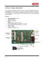
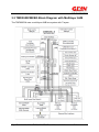
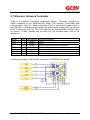
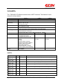
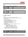
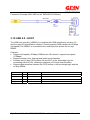
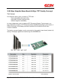
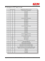
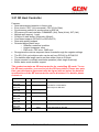
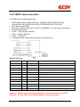
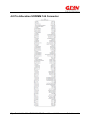
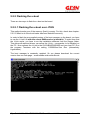
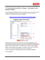
1
Developer Manual
TMPA900 CPU Board
2010 GLYN GmbH & Co. KG
All rights reserved. No part of this documentation may be reproduced or, with the use of electronic
systems, edited copied or transmitted, in any form (print, photocopy, microfilm or another procedure)
without the express authority of the GLYN GmbH & Co. KG, D-65510 Idstein.
The GLYN GmbH & Co. KG, D-65510 Idstein does not accept liability or provide any guarantee with
respect to the contents of this documentation. The GLYN GmbH & Co. KG, D-65510 Idstein retains
the right of revising this work. All programs and descriptions have been created to
the best of our knowledge and tested with great care. However, errors cannot be entirely excluded.
For this reason, the GLYN GmbH & Co. KG does not accept liability for possible errors and
consequential damage resulting from the provision, performance or use of this material.
Glyn GmbH & Co KG – TMPA900-CPU-Board Manual V1.7
Seite 1 von 89
Table of Contents
1.0 Revision List ......................................................................................................... 4
1.1 Contacts ............................................................................................................... 4
2.0 Summary .............................................................................................................. 5
2.1 Product Information TMPA900-CPU BOARD ....................................................... 5
2.2 Energy Consumption at 3.3V (preliminary values)................................................ 6
2.3 Block Diagram ...................................................................................................... 6
2.4 TMPA900 CPU Board Reference Circuitry ........................................................... 7
2.5 Glyn´s Graphic Base Board .................................................................................. 8
2.5.1 Glyn´s Graphic Base Board Connectors............................................................ 9
2.6 Instructions for use ............................................................................................. 11
3.0 Operational Description ...................................................................................... 12
3.1 CPU Core ........................................................................................................... 12
3.2 Memory – Architecture........................................................................................ 13
3.2.1 Nand Flash Memory – Unique Characteristics ............................................... 14
3.3 TMPA900CMXBG Block Diagram with Multilayer AHB ...................................... 16
3.4 Power Supply ..................................................................................................... 17
3.5 RESET................................................................................................................ 19
3.6 External power source control output ................................................................. 19
3.7 Ethernet - Network Controller ............................................................................. 20
3.8 UARTs ................................................................................................................ 21
3.9 USB 2.0 - Device ................................................................................................ 22
3.10 USB 2.0 - HOST ............................................................................................... 23
3.11 I2C .................................................................................................................... 24
3.12 SPI (SSP) ......................................................................................................... 25
3.13 I2S (Inter-IC Sound).......................................................................................... 26
3.14 PWM (Pulse Width Modulation) / 16bit-Timers ................................................. 27
3.15 JTAG ................................................................................................................ 28
3.16 Keys / Keyboard ............................................................................................... 29
3.17 Analog/Digital Converter................................................................................... 29
3.18 Touch Screen Interface (TSI) ........................................................................... 30
3.19 LCD Controller (LCDC)..................................................................................... 31
3.20 Glyn Graphic Base Board & Glyn TFT Family Concept .................................... 33
3.21 SD Host Controller............................................................................................ 35
3.22 CMOS Camera Interface .................................................................................. 36
3.23 Melody/Alarm Generator................................................................................... 37
3.24 Low Frequency Clock Output ........................................................................... 37
4.0 Pin Allocation SODIMM 144 Connector.............................................................. 38
5.0 Software Components ........................................................................................ 44
5.1 Basics - Data Transfer to TMPA900 CPU Board ................................................ 44
5.1.1 ELDIO Download Wizard................................................................................. 44
5.1.2 Basics – Installing J-Link Lite........................................................................... 46
5.1.3 Basics - Installing a TFTP Server .................................................................... 46
Glyn GmbH & Co KG – TMPA900-CPU-Board Manual V1.7
Seite 2 von 89
5.1.4 Basics - Working completely under Linux ........................................................ 46
5.2 u-boot ................................................................................................................. 47
5.2.1 The Boot Process ............................................................................................ 48
5.2.2 Flashing the u-boot .......................................................................................... 49
5.2.2.1 Flashing the u-boot over JTAG ..................................................................... 49
5.2.2.2 Update the u-boot via network (handle with care) ........................................ 50
5.2.2.3 U-boot - Environment Setup ......................................................................... 51
5.2.2.4 IP and MAC Address Setup.......................................................................... 51
5.2.2.5 Configuration of the Display Parameters ...................................................... 52
5.2.2.6 Configuration of the File System Type.......................................................... 52
5.2.2.7 Splash Screen Support................................................................................. 52
5.2.2.8 Erase u-boot Environment. ........................................................................... 53
5.2.2.9 u-boot - NFS Server Setup ........................................................................... 54
5.2.2.10 More u-boot commands.............................................................................. 54
5.2.2.11 What to do if the boot loader has been flashed incorrectly ......................... 56
5.3 Standard Application (IAR Compiler) .................................................................. 58
5.3.1 Debugging the Application (IAR Compiler) ...................................................... 58
5.3.2 Make a Release for Flash (IAR Compiler) ....................................................... 58
5.3.3 Flashing the Application (No Linux) ................................................................. 58
5.3.4 Getting Started with SEGGER Evaluation Software and IAR .......................... 59
6.0 Linux for TMPA900 CPU board .......................................................................... 61
6.1 Major Components of a Linux System ................................................................ 62
6.2 Flashing the Linux Application ............................................................................ 63
6.3 Flash Layout TMPA900-CPU-BOARD................................................................ 63
6.4 Installation Linux Tool chain TMPA900 CPU board ............................................ 64
6.5 Linux Kernel Build............................................................................................... 64
6.5.1 Linux Kernel Source Tree ................................................................................ 64
6.5.2 Linux Kernel Configuration .............................................................................. 66
6.5.3 Compiling the Linux Kernel.............................................................................. 68
6.5.4 Installing the Linux Kernel................................................................................ 68
6.6 Linux File System ............................................................................................... 69
6.7 Linux “Hello World” Example .............................................................................. 71
6.8 µCross – Linux Tool Package............................................................................. 73
7.0 Installing the Display with the Glyn Graphic Base Board .................................... 76
7.1 Other Resolutions/Other Timings – Calculation of the Display Settings ............. 77
8.0 Mechanical Specifications (Formating) ............................................................... 78
8.1 Soldering the TMPA900-CPU-Board – No Connector ........................................ 79
Appendix A: Available u-boot Commands ................................................................ 80
Appendix B: Ordering Information ............................................................................ 82
Appendix C: KC Labs Public Git Server ................................................................... 83
Appendix D: Literature and References.................................................................... 86
Appendix E: CD file directory tree............................................................................. 88
Appendix F: Contact Information .............................................................................. 89
Glyn GmbH & Co KG – TMPA900-CPU-Board Manual V1.7
Seite 3 von 89
1.0 Revision List
V0.1
30.12.2009
CTE/OLE
Document compilation
V0.2
13.01.2010
CTE/OLE
Revision Pin – Allocation
V0.3
18.02.2010
OLE
Revision NAND FLASH
V0.4
07.04.2010
OLE
Manual for flashing the u-boot
V0.5
08.04.2010
OLE
Manual for flashing the application
V1.0
09.04.2010
CTE / HFR
Proof-reading
V1.1
14.04.2010
OLE
Bootloader Correction
V1.2
21.04.2010
OLE
Correction Installation Linux Image
V1.3
18.05.2010
OLE
Corrections
V1.4
21.06.2010
CTE
New chapters 5.0, 6.5 and 7.1
V1.5
05.08.2010
CTE
Completely revised manual
V1.6
18.05.2010
CTE
New ELDIO Download Wizard
V1.7
18.05.2010
CTE
Some Corrections
1.1 Contacts
Christoph Tenbergen
[email protected]
Glyn GmbH & Co KG – TMPA900-CPU-Board Manual V1.7
+49 2157 127-227
Seite 4 von 89
2.0 Summary
This report contains all important technical information regarding the TMPA900-CPUboard SODIMM module. Detailed information about the implemented parts can be
found on the appropriate data sheets and a list with references is at the end of the
document.
2.1 Product Information TMPA900-CPU BOARD
Glyn´s TMPA900-CPU board is a CPU module by Glyn GmbH & Co KG with
Toshiba´s TMPA900CMXBG ARM9 microcontroller. The integrated TFT controller
enables RGB display driving with a resolution of 800x480 with integrated hardware
acceleration. Dispensing with this acceleration enables up to 1024x1024. The
module is a highly efficient and easy-to-integrate processor platform with graphic and
video capability. The board is designed for mounting on a SODIMM socket which is
also available from us – it is a SODIMM 144-pin socket used in the PC field.
Additionally, it is also possible to dispense with the socket and solder the module for
larger series sizes (further information available).
System On-Module
-
Processor TMPA900CMXBG, 200 MHz
RAM 64 MB DDRRAM
ROM 256 MB NAND Flash
Power supply single 3.0V to 3.6V
Size SO-DIMM 144
Temp.-range -20°C..85°C
Key Features
-
10/100Mbps Ethernet (MAC+PHY)
High-speed USB 2.0 Device (480Mbps)
Full-speed USB Host 2.0 (12Mbps)
LCD controller
CMOS camera interface
Interfaces: UART, SD-CARD, I2C, PWM, Keypad, Digital Audio (I2S), 4/5 wire
touch screen
The TMPA900-CPU-Board what comes with the Starterkit is pre-programmed
with the UBoot and a Splashscreen.
There is no Linux-Kernel or other application programmed!
Glyn GmbH & Co KG – TMPA900-CPU-Board Manual V1.7
Seite 5 von 89
2.2 Energy Consumption at 3.3V (preliminary values)
2.3 Block Diagram
Glyn GmbH & Co KG – TMPA900-CPU-Board Manual V1.7
Seite 6 von 89
2.4 TMPA900 CPU Board Reference Circuitry
The complete reference circuitry can be found on the CD.
Glyn GmbH & Co KG – TMPA900-CPU-Board Manual V1.7
Seite 7 von 89
2.5 Glyn´s Graphic Base Board
Glyn´s Graphic Base Board is a platform in order to use the TMPA900-CPU board for
a development. At the same time, it is also the reference design for including a
TMPA900-CPU board. The plans and BOM list can be found on the CD in the file
„Circuit_Diagramm“. Should layout data be required, this can also be provided
against an NDA.
Features
•
•
•
•
•
•
•
•
•
•
•
144 PIN SODIMM connector
Ethernet connector
USB host connector
USB device connector
RS232
WM8983 Audio Codec by Wolfson
SD card sockets (SD-Host controller and via SPI)
Glyn TFT concept connector für 3.5“ – 7“ TFTs
JTAG interface
100mm x 160mm
Single power supply 5-35V
Glyn GmbH & Co KG – TMPA900-CPU-Board Manual V1.7
Seite 8 von 89
2.5.1 Glyn´s Graphic Base Board Connectors
CN300
Port_A: IOs, Key In
Port_B: IOs, Key Out
CN301
Port_G: IOs, SD-Host
CN302
Port_N: IOs, UART0, ext. Interrupts
CN303
Port_T: IOs, UART1, SPI0
Port_F : IOs, I2C1, UART2, INTC
CN304
Port_D: IOs, ADC IN, I2S1
CN305
Port_L: IOs, I2S0, SPI1
Port_C: IOs,PWM, Melody Alarm, FSOUT,PWE
Glyn GmbH & Co KG – TMPA900-CPU-Board Manual V1.7
Seite 9 von 89
CN200
Glyn GmbH & Co KG – TMPA900-CPU-Board Manual V1.7
CN201
Seite 10 von 89
2.6 Instructions for use
The standard measures of precaution regarding touching and operating circuitry in
low voltage ranges apply. Electrostatic discharging which may damage parts is to be
avoided.
The board may be plugged in or out only when the supply voltage is switched off.
The parts used on the TMPA900 CPU board are specified for use between -20 and
+85 Grad Celsius. The TMPA900 CPU board requires a DC voltage of 3.3V ± 0.2V.
Glyn GmbH & Co KG – TMPA900-CPU-Board Manual V1.7
Seite 11 von 89
3.0 Operational Description
This chapter provides a brief description of the module and its interfaces.
3.1 CPU Core
Note that this document provides only an overview of the CPU block. Please contact
ARM Holdings for operation details and refer to the TMPA900CMXBG manual.
The TMPA900CM has a built-in 32-bit RISC processor ARM926EJ-S manufactured
by ARM. The schematic diagram of the ARM926EJ-S core is shown below.
The TMPA900CM does not feature the functions shown below.
1. Coprocessor I/F
2. Embedded ICE RT
3. TCM I/F
4. ETM9TM I/F
Glyn GmbH & Co KG – TMPA900-CPU-Board Manual V1.7
Seite 12 von 89
3.2 Memory – Architecture
The TMPA900 is characterised by a multilayer AHB bus. The advantage over
conventional architectures is the higher internal data throughput. To expand on this
concept, there are two memory controllers for the external flash and RAM. The first is
responsible for communication with NORFLASH, SRAM or SDRAM and the second
is responsible for communication with NORFLASH, SRAM und DDR SDRAM. The
external memory chips are each directly connected to one of these controllers.
The CSs of the external NAND flash are connected to pin D7/D8 on the TMPA900.
The CSs of the external SRAM/DDRRAM are connected to pin K12 on the TMPA900
The TMPA900 has two operating modes – the external memory mode and the
internal boot ROM mode which are specified by the external mode pins AM0 and
AM1. Pin AM0 is set to high. Pin AM1 is connected to the expansion connector and
marked BOOT (PIN132).
AM1
AM1
HIGH
LOW
BOOT (start from internal Boot ROM)
Start from external bus/memory (16-bit Bus)
Due to the internal structure of NAND memories, it is not possible to run a program
directly from this memory. In fact, the user program code has to be copied from the
NAND memory to the external RAM before starting the program. Access to the
NAND flash takes place in a multiplexed 8-Bit mode.
The process has not been disclosed in detail. Should the customer require more
information, we can request personalised documentation at Toshiba. This is free of
charge.
Glyn GmbH & Co KG – TMPA900-CPU-Board Manual V1.7
Seite 13 von 89
3.2.1 Nand Flash Memory – Unique Characteristics
•
•
•
•
•
When it is erased, all bits are set to 1' (you will see 0xff on all bytes in a hexdump)
You can change as many bits as you want to '0'
You cannot set a bit back to '1' by using a regular write.
You have to erase a whole erase block to do so
The number of erase cycles per block is limited. Once you have reached the limit,
some bits will not get back to 0xff. In the case of the in Samsung Flash K9F2G08
this is 100.000 guaranteed per-block erase cycles.
NAND page
A NAND page consists of a number of data bytes plus a number of out-of-band
(OOB) bytes.
Only the data bytes are used for application data. The OOB bytes are used for
• Marking an erase block as bad (first or second page of erase block)
• Storing ECC (error correction codes)
• Storing file system specific information (JFFS2)
NAND erase block
An erase block consists of multiple pages. In K9F2G08 every erase block has 64
pages.
Glyn GmbH & Co KG – TMPA900-CPU-Board Manual V1.7
Seite 14 von 89
Problem: Bad Blocks
NAND memory apparently gets shipped with blocks that are already bad. The vendor
just marks those blocks as bad, thus resulting in higher yield and lower per-unit cost.
The flash contains four kinds of blocks (16kBytes):
•
•
•
•
Factory default bad blocks
o Samsung marks the 6th OOB byte as non 0xFF in the first and/or second
page in blocks that are bad
Worn-out bad blocks
Good blocks
The first block. This block is guaranteed to not require error correction up to 1000
writes. This is needed as the initial boot code can't do ECC.
It is also guaranteed that a minimum of 2008 blocks (out of the total 2048) are good.
This means up to 40 blocks (5.1MBytes) can be dead.
More about bad block handling in chapter 5.0 u-boot!
Glyn GmbH & Co KG – TMPA900-CPU-Board Manual V1.7
Seite 15 von 89
3.3 TMPA900CMXBG Block Diagram with Multilayer AHB
The TMP900CM uses a multilayer AHB bus system with 7 layers.
Glyn GmbH & Co KG – TMPA900-CPU-Board Manual V1.7
Seite 16 von 89
3.4 Power Supply
The parts used on the TMPA900 CPU board are specified for use between -20 and
+85 Grad Celsius. The TMPA900 CPU board requires a DC voltage of 3.3V ± 0.2V.
The power is fed over the VDD3R3 pins. This power runs through some filters and is
outputted over VDD3V3. External components which aren’t supplied by the module
should be supplied over VDD3V3.
The filters are switched between VIN/VDD3R3 and VDD3V3, so the voltage peak has
the same effect on external components as on the module. The EMV critical part
should be connected via the filters.
Power Supply Pins VDD3R3:
Signal
PIN
Input/Output
VDD3R3
136
Input
VDD3R3
138
Input
VDD3R3
140
Input
VDD3R3
142
Input
Function Remarks
DC-IN supply: 3.3V ± 0.2V
Power Output Pins VDD3V3:
Signal
PIN
Input/Output
VDD3V3
3
Output
VDD3V3
4
Output
VDD3V3
61
Output
VDD3V3
62
Output
VDD5W0
5
-
Function Remarks
DC-OUT VDD3R3 filtered
Not connected!
Glyn GmbH & Co KG – TMPA900-CPU-Board Manual V1.7
Seite 17 von 89
Ground Pins:
Signal
PIN
GND
1
GND
2
GND
11
GND
12
GND
21
GND
22
GND
31
GND
32
GND
41
GND
42
GND
51
GND
52
GND
63
GND
64
GND
73
GND
74
GND
83
GND
84
GND
93
GND
94
GND
103
GND
104
GND
113
GND
114
GND
123
GND
124
GND
133
GND
134
GND
143
GND
144
Input/Output
Function Remarks
Ground
Glyn GmbH & Co KG – TMPA900-CPU-Board Manual V1.7
Seite 18 von 89
3.5 RESET
Before resetting the TMPA900CM, make sure that the power supply voltage is within
the operating range, oscillation from the internal oscillator is stable at at least 20
system clock cycles (0.8 μs @ X1 = 25 MHz), and the RESET input pin is pulled Low.
When the TMPA900CM is reset, the PLL stops, the PLL output is unselected, and the
clock gear is set to TOP (1/1).
The system clock therefore operates at 25 MHz (X1 = 25 MHz).
Signal
PIN
Input/Output
RESET
112
Input
Function Remarks
RESET
3.6 External power source control output
Signal
PIN
Input/Output
PWE
(PORT_C2)
110
Output
Function Remarks
This pin controls ON/OFF of the external power source.
The "H" level is output during regular operations, and the
"L" level is output during standby mode.
Glyn GmbH & Co KG – TMPA900-CPU-Board Manual V1.7
Seite 19 von 89
3.7 Ethernet - Network Controller
There is an LAN9221i (Industrial Temperature Range) – Ethernet controller by
SMSC integrated on the TMPA900-CPU board. This supports 10/100 MBit data
communication. The Fifo – Select connection (Pin13) is connected to address A12 of
the TMPA900. A 330Ohm series resistor has already been integrated for the network
LEDs. Furthermore, the TXP, TXN, RXP and RXN are connected by a 490Ohm pullup resistor. A MAC address has not been set; the firmware takes care of the
assignment.
Signal
LED1
LED2
CT
RXP
RXN
TXP
TXN
PIN
6
8
10
14
16
18
20
Input/Output
Output
Output
Output
Input
Input
Output
Output
Function Remarks
LED1
LED2
AVDD Output to Ethernet Magnetics
Receive Positive
Receive Negative
Transmit Positive
Transmit Negative
Connection Example: RJ45 Female Connector on TMPA900-CPU-Board
Glyn GmbH & Co KG – TMPA900-CPU-Board Manual V1.7
Seite 20 von 89
3.8 UARTs
The TMPA900-CPU-Board contains three UART channels. The feature of each
channel is shown below.
Transmit FIFO
Receive FIFO
Transmit/Receive
data format
FIFO ON/OFF
Interrupt
baud rate generator
DMA
IrDA 1.0 Function
Control pins
Hardware flow
control
UART 0
UART 1
UART 2
8-bit width / 16 location deep
12-bit width /16location deep
DATA bits : 5,6,7,8bits can be selected
PARITY: use / no use
STOP bit:1bit / 2bits
ON (FIFO mode)/
OFF (characters mode)
(1) Combined interrupt factors are output to interrupt controller.
(2) The permission of each interrupt factor is programmable.
Generates a common transmit and receive internal clock from the UART
internal reference clock input.
Supports baud rates of up to 6.15Mbps at fPCLK = 100MHz.
Support
NO support
support
(1) Max data rate:
N/A
N/A
115.2kbps(half-duplex)
(2) support low power mode
U0RXD
U1RXD
U2RXD
U0TXD
U1TXD
U2TXD
U0CTSn
U0CTSn (Clear To Send)
U0DCDn (Data Carrier Detect)
U0DSRn (Data Set Ready)
U0RIn (Ring Indicator)
U0RTSn(Request To Send)
U0DTRn (Data Terminal Ready)
RTS support
NC
N/A
CTS support
UART0:
Signal
U0RTSn
(PORT_N7)
U0DTRn
(PORT_N6)
U0RIn
(PORT_N5)
U0DSRIn
(PORT_N4)
U0DCDn
(PORT_N3)
U0CTSn
(PORT_N2)
U0RXD
(PORT_N1)
U0TXD
(PORT_N0)
PIN
Input/Output
Function Remarks
24
Output
Output modem control line RTD(Request To Send)
26
Output
Output modem control line DTR (Data Terminal Ready)
28
Input
Modem status signal RI (Ring Indicator)
30
Input
Modem status signal DSR (Data Set Ready)
34
Input
Modem status signal DCD (Data Carrier Detect)
36
Input
UART0 data can be transmitted (Clear to send)
38
Input
UART0 receive data
40
Output
UART0 transmission data
Glyn GmbH & Co KG – TMPA900-CPU-Board Manual V1.7
Seite 21 von 89
UART1:
Signal
U1RXD
(PORT_T5)
U1TXD
(PORT_T4)
PIN
Input/Output
44
Input
46
Output
PIN
Input/Output
58
Input
60
Output
Function Remarks
UART1 receive data
UART1 transmission data
UART2:
Signal
U2RXD
(PORT_F7)
U2TXD
(PORT_F6)
Function Remarks
UART2 receive data
UART2 transmission data
3.9 USB 2.0 - Device
Features:
• Conforms with universal serial bus specification Rev. 2.0
• Supports both high-speed and full-speed (low-speed is not supported).
• Supports Chirp.
• USB protocol processing
• Detects SOF/USB_RESET/SUSPEND/RESUME.
• Generates and checks packet IDs.
• Generates and checks data synchronization bits
(DATA0/DATA1/DATA2/MDATA).
• Checks CRC5, generates and checks CRC16.
• Supports PING.
• Supports 4 transfer modes (Control/Interrupt/Bulk/Isochronous).
• Supports 4 endpoints:
o Endpoint 0: Control 64 bytes × 1 FIFO
o Endpoint 1: Bulk (IN) 512 bytes × 2 FIFOs
o Endpoint 2: Bulk (OUT) 512 bytes × 2 FIFOs
o Endpoint 3: Interrupt (IN) 64 bytes × 1 FIFO
• Supports dual packet mode (except for Endpoint 0).
• Interrupt source signal to interrupt controller: INTS[21]
Signal
PIN
Input/Output
Function Remarks
USB_DDP
17
Input/Output
USB Device pin (D+)
USB_DDM
19
Input/Output
USB Device pin (D-)
Glyn GmbH & Co KG – TMPA900-CPU-Board Manual V1.7
Seite 22 von 89
Connection Example: MINI USB on the TMPA900-CPU-Board
3.10 USB 2.0 - HOST
The USB host controller (USBHC) is compliant with USB specification revision 2.0
and the open HCI specification release 1.0a and supports USB transfers at 12 Mbps
(full-speed).The USBHC is connected to the multi-layer bus system via on-chip
SRAM.
Features:
• Supports full-speed (12 Mbps) USB devices. But doesn’t supports low-speed
(1.5Mbps)
• Supports control, bulk, interrupt and isochronous transfers.
• Contains two 16-byte FIFO buffers (IN and OUT) in the bus bridge logic for
connecting with the CPU, allowing a maximum of 16-byte burst transfers.
• Supports data transfers between the FIFO buffers in the bus bridge logic and the
on-chip SRAM.
Signal
PIN
Input/Output
Function Remarks
USB_OC
7
Input
Over current detect for USB host
USB_PON
9
Output
USB_HDP
13
Input/Output
USB host data (D+)
USB_HDM
15
Input/Output
USB host data (D-)
Power on enable for USB host
Glyn GmbH & Co KG – TMPA900-CPU-Board Manual V1.7
Seite 23 von 89
Connection Example: USB host type A on the TMPA900 CPU board
3.11 I2C
This module operates in I2C bus mode and is compliant with the typical I2C bus
standard (Philips specifications).
Features:
• Contains two channels (ch0 and ch1).
• Allows selection between master and slave.
• Allows selection between transmission and reception.
• Supports multiple masters (arbitration, clock synchronization recognition).
• Supports standard mode and fast mode (fastest baud rate in master mode: 89.91
kHz andn357.14 kHz, respectively, at fPCLK = 100 MHz)
• Supports the addressing format of 7 bits only.
• Supports transfer data sizes of 1 to 8 bits.
• Provides one transfer (transmission or reception) complete interrupt (levelsensitive).
• Can enable or disable interrupts. (Interrupt source for I2C ch0: INTS[6], Interrupt
source for I2C ch1: INTS[7])
I2C Channel 0:
Normally used for USB host
Signal
I2C0CL
(USB_OC)
I2C0DA
(USB_PON)
PIN
Input/Output
Function Remarks
7
Input/Output
I2C clock I/O
9
Input/Output
I2C data I/O
PIN
Input/Output
Function Remarks
60
Input/Output
I2C clock I/O
58
Input/Output
I2C data I/O
I2C Channel 1:
Signal
I2C1CL
(Port_F6)
I2C1DA
(Port_F7)
Glyn GmbH & Co KG – TMPA900-CPU-Board Manual V1.7
Seite 24 von 89
3.12 SPI (SSP)
Features:
• Contains two channels (ch0 and ch1).
• Communication protocol includes SPI : 3 types
• Master/ slave mode support
• Transmit FIFOs 16-bit wide, 8 locations deep
• Receive FIFOs 16-bit wide, 8 locations deep
• Transmit/Receive data size 4 to 16 bits
• Interrupt type:
o Transmits interrupt
o Receives interrupt
o Receives overrun interrupt
o Timeout interrupt
• Baud rate master mode: fPCLK/2 (Max 20 Mbps)
• Slave mode: fPCLK/12 (Max 8.33 Mbps)
• DMA Support
• Internal loop back test mode available
SPI (SSP) Channel 0:
Signal
SP0D
(Port_T3)
SP0DO
(Port_T2)
SP0CLK
(Port_T1)
SP0FSS
(Port_T0)
PIN
Input/Output
Function Remarks
48
Input
50
Output
54
Input/Output
Clock pin for SSP0
56
Input/Output
FSS pin for SSP0
PIN
Input/Output
Function Remarks
96
Input
98
Output
100
Input/Output
Clock pin for SSP1
102
Input/Output
FSS pin for SSP1
Data input pin for SSP0
Data output pin for SSP0
SPI (SSP) Channel 1:
Signal
SP1DI
(Port_L3)
SP1DO
(Port_L2)
SP1CLK
(Port_L1)
SP1FSS
(Port_L0)
Data input pin for SSP1
Data output pin for SSP1
Glyn GmbH & Co KG – TMPA900-CPU-Board Manual V1.7
Seite 25 von 89
3.13 I2S (Inter-IC Sound)
The TMPA900CM contains a serial input/output circuit compliant with the I2S format.
By connecting an external audio LSI, such as an AD converter or DA converter, the
I2S interface can support the implementation of a digital audio system.
Features:
Transmit/Receive
Modes
Data formats
FIFO buffer
Data length
Interrupts
Channel 0
Channel 1
Receive only
Transmit only
Receive master mode
Transmit master mode
Receive slave mode
Transmit slave mode
Full-duplex master mode
Full-duplex slave mode
Clock through mode
(1) I2S format-compliant
(2) Stereo/monaural
(3) MSB first/LSB first selectable
(4) Left-justified supported (synchronous to WS, no delay)
2 × 8 words
2 × 8 words
16 bits only
16 bits only
FIFO overflow interrupt
FIFO overflow interrupt
FIFO underflow interrupt
FIFO underflow interrupt
I2S Channel 0:
Signal
I2S0MCLK
(Port_L3)
I2S0DATI
(Port_L2)
I2S0CLK
(Port_L1)
I2S0WS
(Port_L0)
PIN
Input/Output
96
Output
Function Remarks
I2S0 master clock output for receive circuit
Input
I2S0 receive serial data input
98
100
Input/Output
I2S0 serial clock Input/output
102
Input/Output
I2S0 word select Input/output
PIN
Input/Output
Function Remarks
86
Output
I2S1 master clock output for receive circuit
88
Output
I2S1 transmission serial data output
90
Input/Output
I2S1 serial clock Input/output
92
Input/Output
I2S1 word select Input/output
I2S Channel 1:
Signal
I2S1MCLK
(Port_M3)
I2S2DATO
(Port_M2)
I2S3CLK
(Port_M1)
I2S4WS
(Port_M0)
Glyn GmbH & Co KG – TMPA900-CPU-Board Manual V1.7
Seite 26 von 89
3.14 PWM (Pulse Width Modulation) / 16bit-Timers
The TMPA900 CPU board contains six cannels of 16-bit timers. Two of them, timer 0
and timer 2 support PWM (Pulse Width Modulation) output.
1) Free-running mode
2) Periodic timer mode
3) PWM function support
The circuit consists of three blocks, each associated with two channels. Of the three
blocks, block 1 and block 2 support PWM (Pulse Width Modulation) output.
Block 1
Free-Running
Periodic Timer
PWM
Interrupt
Source Signal
Block 2
Timer0
Timer1
Timer2
Timer3
●
●
●
●
●
●
●
●
●
●
N/A
PWM0OUT
(Port_C3)
INTS[2]
x
PWM2OUT
(Port_C4)
INTS[3]
Block 3
Timer4
Timer5
●
●
N/A
x
Signal
PIN
Input/Output
PWM0OUT
(Port_C3)
PWM2OUT
(Port_C4)
108
Output
Timer 0 PWM output port
106
Output
Timer 2 PWM output port
●
●
N/A
x
x
INTS[4]
Function Remarks
Each timer block, containing two channels of timer circuits, comprises two
programmable, 16-bit free-running decrement counters. The TIMCLK input is used
for counter operation. This clock can be selected from the internal system clock
divided by two (fPCLK/2) and fs (32.768 kHz).
Glyn GmbH & Co KG – TMPA900-CPU-Board Manual V1.7
Seite 27 von 89
Figure diagram of the timer block (Timer 0 and Timer 1).
3.15 JTAG
The TMPA900CMXBG provides a boundary scan interface that is compatible with
Joint Test Action Group (JTAG) specifications and uses the industrial standard JTAG
protocol (IEEE Standard 1149.1•1990 <Includes IEEE Standard 1449.1a•1993>).
Signal
PIN
Input/Output
Function Remarks
TDO
116
Output
Data output pin for JTAG
TCK RTN
118
Output
JTAG test feedback serial clock output
TCK
120
Input
Clock pin for JTAG
TMS
122
Input
Data for JTAG
TDI
126
Input
Data input pin for JTAG
TRST
128
Input
RESET pin for JTAG
JTAG
130
Input
BOOT
132
Input
Boundary scan switching pin, ICE/JTAG test select input
(compatible with the Enable signal) -> 0: ICE 1: JTAG
AM1 Pin
Glyn GmbH & Co KG – TMPA900-CPU-Board Manual V1.7
Seite 28 von 89
3.16 Keys / Keyboard
Port A can be used not only as a general-purpose input pin with pull up, but also as a
key input pin. By enabling interrupts, Port A is used as key input pins (KI3-KI0).
Port A can be used without pull up.
Port B can be used not only as general-purpose output pins, but also as key output
pins. By enabling open-drain output, Port B is used as key output (KO3-KO0).
Signal
PIN
Input/Output
Port A0 (KI0)
29
Input
Port A1 (KI1)
27
Input
Port A2 (KI2)
25
Input
Port A3 (KI3)
23
Input
Port B0 (KO0)
33
Output
Port B1 (KO1)
35
Output
Port B2 (KO2)
37
Output
Port B3 (KO3)
39
Output
Function Remarks
Port A0 to A3: Input ports
Key input KI0 to KI3: Pins for key-on wake up 0 to 3
(with Schmitt input and pull-up resistor)
Port B0 to B3: Output ports
Key output KO0 zp KO3: Key out pins 0 to 3
(open-drain can be set)
3.17 Analog/Digital Converter
A 10-bit serial conversion analog/digital converter (AD converter) with eight channels
of analog input is built-in. Four channels (AN4-AN7) are normally used for touch
screen interface.
Signal
AN0
(Port_D0)
AN1
(Port_D1)
AN2
(Port_D2)
AN3
(Port_D3)
PIN
Input/Output
82
Input
80
Input
78
Input
76
Input
Function Remarks
Port D0 to D3: Input ports
Analog input AN0 to AN3: AD Converter Input Pins
Pins normally used for Touch Screen Interface
Signal
AN7
(TSI_PY)
AN6
(TSI_PX)
AN5
(TSI_MY)
AN4
(TSI_MX)
PIN
Input/Output
65
Output
67
Output
69
Output
71
Output
Function Remarks
Port D4 to D7: Input ports
Analog input AN4 to AN7: AD Converter Input Pins
Glyn GmbH & Co KG – TMPA900-CPU-Board Manual V1.7
Seite 29 von 89
3.18 Touch Screen Interface (TSI)
An interface for a 4-terminal resistor network touch screen is built-in. The TSI easily
supports two procedures: touch detection and X/Y position measurement. Each
procedure is performed.
TMPA900_CPU_BOARD
Signal
TSI_PY
(Port_D7/AN7)
TSI_PX
(Port_D6/AN6)
TSI_MY
(Port_D5/AN5)
TSI_MX
(Port_D4/AN4)
PIN
Input/Output
Function Remarks
65
Output
Y-plus: Y-connecting pin for touch panel
67
Output
X-plus: X-connecting pin for touch panel
69
Output
Y-minus: Y-connecting pin for touch panel
71
Output
X-minus: X-connecting pin for touch panel
Glyn GmbH & Co KG – TMPA900-CPU-Board Manual V1.7
Seite 30 von 89
3.19 LCD Controller (LCDC)
SUPPORTED DISPLAY COLORS & DISPLAY RESOLUTION
Display colours: from 256 to16 million:
Data bus width
24 bit
18 bit
16 bit
12 bit
8 bit
RGB
R8:G8:B8
R6:G6:B6
R5:G6:B5
R4:G4:B4
R3:G3:B2
Display colours
16 million
262 144
65 536
4 096
256
Supported display resolution:
Up to WVGA with LCD data process accelerator:
•
•
•
Scaling function (expansion/reduction)
Filter function (bi-cubic convolution)
Image blending function (font blending)
Up to 1024 x 1024 without accelerator and limited colour depth.
Glyn GmbH & Co KG – TMPA900-CPU-Board Manual V1.7
Seite 31 von 89
LCD Interface Signals:
Signal
PIN
Input/Output
Function Remarks
L_CLLP
116
Output
Data output pin for JTAG
L_CLFP
118
Output
JTAG test feedback serial clock output
L_CLAC
120
Input
Clock pin for JTAG
L_CLCP
122
Input
Data for JTAG
Signal
PIN
Input/Output
L_D0
141
Output
LCD data driver line
L_D1
139
Output
LCD data driver line
L_D2
137
Output
LCD data driver line
L_D3
135
Output
LCD data driver line
L_D4
131
Output
LCD data driver line
L_D5
129
Output
LCD data driver line
L_D6
127
Output
LCD data driver line
L_D7
125
Output
LCD data driver line
L_D8
121
Output
LCD data driver line
L_D9
119
Output
LCD data driver line
L_D10
117
Output
LCD data driver line
L_D11
115
Output
LCD data driver line
L_D12
111
Output
LCD data driver line
L_D13
109
Output
LCD data driver line
L_D14
107
Output
LCD data driver line
L_D15
105
Output
LCD data driver line
L_D16
101
Output
LCD data driver line
L_D17
99
Output
LCD data driver line
L_D18
97
Output
LCD data driver line
L_D19
95
Output
LCD data driver line
L_D20
91
Output
LCD data driver line
L_D21
89
Output
LCD data driver line
L_D22
87
Output
LCD data driver line
L_D23
85
Output
LCD data driver line
Function Remarks
Glyn GmbH & Co KG – TMPA900-CPU-Board Manual V1.7
Seite 32 von 89
3.20 Glyn Graphic Base Board & Glyn TFT Family Concept
The Concept
Our objective was to offer a number of TFTs that . . .
1) are compatible with each other,
2) provide a modern interface and
3) have long-term availability.
In close collaboration with our partner EDT (Emerging Display Technologies), we
have selected a number of TFTs that have been modified according to your needs. A
PCB on the back of the display provides important functionalities as well as a
common interface.
The family concept displays can be connected to the graphic base board (starter kit)
directly. All display signals are lead through the SODIMM slot.
7.0" - 5.7" - 5.0" - 4.3" - 3.5"
Glyn GmbH & Co KG – TMPA900-CPU-Board Manual V1.7
Seite 33 von 89
Pin Assignment of TFT Family Concept
Glyn GmbH & Co KG – TMPA900-CPU-Board Manual V1.7
Seite 34 von 89
3.21 SD Host Controller
Features:
• Data transmission/reception in frame units
• Error check: CRC7 (for commands), CRC16 (for Data)
• Synchronous method: bit synchronous by SDCLK
• SD memory/IO card interface: COMMAND (1bit), Data (4 bits), INT (1bit)
• Multiple port support: 1 card
• 512byte ×2 data buffer: 256words×16bits×2
• Card detect support (SDCxCD or SDCxDAT3)
• Data write protect support
• Detected below Status error
o SDbuffer underflow /overflow
o timeout (response, other
o END error, CRC error, CMD error
• Recognizes the various response frame formats through the register settings
• The SD_CLK cycle division ratio can be set from fPCLK/2 to fPCLK/512
• The transfer data length can be set from either 1byte to 512byte
• Sector counter for multiple read/write operation (read: single read only)
• Buffer status mode transfer support
This product contains an SD host controller for controlling SD cards. To use
the SD host controller, you need to join the SD Association. Please also note
that a non-disclosure agreement must be signed with us before the detailed
specifications of the SD host controller can be disclosed. For details, please
contact us.
Signal
SDC0DAT0
(Port_G0)
SDC0DAT1
(Port_G1)
SDC0DAT2
(Port_G2)
SDC0DAT3
(Port_G3)
SDC0CMD
(Port_G4)
SDC0WP
(Port_G5)
SDC0CD
(Port_G6)
SDC0CLK
(Port_G7)
PIN
Input/Output
Function Remarks
59
Input/Output
57
Input/Output
55
Input/Output
53
Input/Output
49
Input/Output
47
Input
Write-protect input pin for SD card
45
Input
Card detection input pin for SD card
43
Input
Clock output pin for SD card
SDC0DAT0 to SDC0DAT3:
Data I/O pin for SD card
Command I/O pin for SD card
Glyn GmbH & Co KG – TMPA900-CPU-Board Manual V1.7
Seite 35 von 89
3.22 CMOS Camera Interface
The CMSI has the following features:
•
•
•
•
•
•
•
•
SXGA(1280×1024), 4VGA(1280×960), VGA(640×480), QVGA(320×240),
Special(320×180), QQVGA(160×120), CIF(352×288), QCIF(176×144)
Input data format CRGB
Input data sampling ratio 8-bit YUV4:2:2 or RGB888 if no color space conversion)
Downscaling function
4VGA → VGA, QVGA, QQVGA
VGA → QVGA, QQVGA
QVGA → QQVGA
Trimming function: Data can be trimmed to a desired size.
Signal
PIN
Input/Output
Function Remarks
L_D12(CMSPCK)
111
Input
Clock input for CMOS sensor
L_D13(CMSHSY)
109
Input
Horizontal synchronization input for CMOS sensor
L_D14(CMSHBK)
107
Input
Valid data detect input for CMOS sensor
L_D15(CMSVY)
105
Input
Vertical synchronization input for CMOS sensor
L_D16(CMSD0)
101
Input
CMOS data driver line
L_D17(CMSD1)
99
Input
CMOS data driver line
L_D18(CMSD2)
97
Input
CMOS data driver line
L_D19(CMSD3)
95
Input
CMOS data driver line
L_D20(CMSD4)
91
Input
CMOS data driver line
L_D21(CMSD5)
89
Input
CMOS data driver line
L_D22(CMSD6)
87
Input
CMOS data driver line
L_D23(CMSD7)
85
Input
CMOS data driver line
Attention: CMOS camera Interface uses some of the same pins as the LCDC
data bus – so only 12bit colour (4096 display colours) is possible.
Glyn GmbH & Co KG – TMPA900-CPU-Board Manual V1.7
Seite 36 von 89
3.23 Melody/Alarm Generator
Melody Generator
Based on the low-speed clock (32.768 kHz), clock wave forms can be generated at
any frequency from 4 Hz to 5461 Hz and outputted from the MLDALM pin.
By connecting a buzzer etc outside, melody sounds can easily be played.
Alarm Generator
Can generate eight patterns of alarm output.
Can generate five types of fixed-interval interrupts (1 Hz, 2 Hz, 64 Hz,
512 Hz and 8192 Hz).
By connecting a buzzer etc outside, alarm sounds can easily be played.
Signal
PIN
Input/Output
MLDALM
(PORT_C3)
108
Output
Function Remarks
Melody/alarm output pin
3.24 Low Frequency Clock Output
Signal
PIN
Input/Output
FSOUT
(PORT_C4)
106
Output
Function Remarks
Low frequency output clock pin
Glyn GmbH & Co KG – TMPA900-CPU-Board Manual V1.7
Seite 37 von 89
4.0 Pin Allocation SODIMM 144 Connector
Glyn GmbH & Co KG – TMPA900-CPU-Board Manual V1.7
Seite 38 von 89
PINOUT (1/5)
Numper of
Pin
1-2
3-4
5
6
7
Pin Name
Input/Output
Function Remarks
GND
VDD3V3
nc
LED1
USB_OC
Output
Output
Output
Input/Output
Input/Output
Input
8
9
LED2
USB_PON
10
11-12
13
14
15
16
17
18
19
20
21-22
23
CT
GND
USB_HDP
RXP
USB_HDM
RXN
USB_DDP
TXP
USB_DDM
TXN
GND
Port A3
24
Port N7
Ground
Power
leave open
Ethernet LED1: Speed LED
PC7: I/O port
I2C0DA: I2C data I/O
INT9: Interrupt request pin9: an interrupt request pin that
can program the rising/falling edge
USBOCn: Over Current detect for USB Host
Ethernet LED2: Link/Active LED
PC6: Port C6: I/O port
I2C0CL: I2C clock I/O
USBPON: Power On Enable for USB Host
Ether
Ground
USB Host pin (D+)
Ethernet
USB Host pin (D-)
Ethernet
USB Device pin (D+)
Ethernet
USB Device pin (D-)
Ethernet
Ground
PA3: Input port
Key input KI3: Pin for key-on wake up
(with Schmitt input and pull-up resistor)
PN7: I/O port
U0RTSn: Output modem control line RTD(Request To
Send)
INTG: Interrupt request pin G: an interrupt request pin that
can program the rising/falling edge
Port A2: Input port
Key input KI2: Pin for key-on wake up
(with Schmitt input and pull-up resistor)
PN6: I/O port
U0DTRn: Output modem control line DTR (Data Terminal
Ready)
INTF: Interrupt request pin F: an interrupt request pin that
can program the rising/falling edge
Port A1: Input port
Key input KI1: Pin for key-on wake up
(with Schmitt input and pull-up resistor)
PN5: I/O port
U0RIn: Modem status signal RI (Ring Indicator)
INTE: Interrupt request pin E: an interrupt request pin that
can program the rising/falling edge
Port A0: Input port
Key input KI0: Pin for key-on wake up
(with Schmitt input and pull-up resistor)
PN4: I/O port
U0DSRIn: Modem status signal DSR (Data Set Ready)
INTD: Interrupt request pin D: an interrupt request pin that
can program the rising/falling edge
Ground
Input
Output
Input/Output
Input/Output
Output
-
Input
Input/Output
Output
Input
25
Port A2
Input
26
Port N6
Input/Output
Output
Input
27
Port A1
Input
28
Port N5
Input/Output
Input
Input
29
Port A0
Input
30
Port N4
Input/Output
Input
Input
31-32
GND
-
Glyn GmbH & Co KG – TMPA900-CPU-Board Manual V1.7
Seite 39 von 89
PINOUT (2/5)
Numper of
Pin
33
Pin Name
Input/Output
Function Remarks
Port B3
34
Port N3
35
Port B2
36
Port N2
Output
Output
Input/Output
Input
Output
Output
Input/Output
Input
37
Port B1
38
Port N1
38
Port B0
40
Port N0
41-42
43
GND
Port G7
44
Port T5
45
Port G6
46
Port T4
47
Port G5
48
Port T3
49
Port G4
50
Port T2
51-52
53
GND
Port G3
54
Port T1
55
Port G2
56
Port T0
57
Port G1
58
Port F7
59
Port G0
60
Port F6
PB3: Output port
KO3: Key out pins (open-drain can be set)
PN3: I/O port
U0DCDn: Modem status signal DCD (Data Carrier Detect)
PB2: Output port
KO2: Key out pins (open-drain can be set)
Port N2: I/O port
U0CTSn: UART function 0 data can be transmitted
(Clear to send)
PB1: Output port
KO1: Key out pins (open-drain can be set)
Port N1: I/O port
U0RXD: UART function 0 receive data
SIR0IN: Data input pin for IrDA1.0
PB0: Output port
KO0: Key out pins (open-drain can be set)
Port N0: I/O port
UART function 0 transmission data
Data output pin for IrDA1.0
Ground
Port G7: I/O port
SDC0CLK: Clock output pin for SD card
Port T5: I/O port
U1RXD: UART function 1 receive data
Port G6: I/O port
SDC0CD: Card detection input pin for SD card
Port T4: I/O port
U1TXD: UART function 1 transmission data
Port G5: I/O port
SDC0WP: Write-protect input pin for SD card
PT3: I/O port
SP0DI: Data input pin for SSP0
Port G4: I/O port
SDC0CMD: Command I/O pin for SD card
Port T2: I/O port
SP0DO: Data output pin for SSP0
Ground
PG3: I/O port
SDC0DAT3: Data I/O pin for SD card
Port T1: I/O port
SP0CLK: Clock pin for SSP0
PG2: I/O port
SDC0DAT2: Data I/O pin for SD card
PT0: I/O port
SP0FSS: FSS pin for SSP0
PG1: I/O port
SDC0DAT1: Data I/O pin for SD card
PF7: I/O port
I2C1DA: I2C data I/O
INTC: Interrupt request pin C: an interrupt request pin that
can program the rising/falling edge
U2RXD: UART function 2 receive data
PG0: I/O port
SDC0DAT0: Data I/O pin for SD card
PF6: I/O port
I2C1CL: I2C clock I/O
U2TXD: UART function 2 transmission Data
61-62
63-64
VDD3V3
GND
Output
Output
Input/Output
Input
Input
Output
Output
Input/Output
Output
Output
Input/Output
Input/Output
Input/Output
Input
Input/Output
Input
Input/Output
Output
Input/Output
Input
Input/Output
Input
Input/Output
Input/Output
Input/Output
Output
Input/Output
Input/Output
Input/Output
Input/Output
Input/Output
Input/Output
Input/Output
Input/Output
Input/Output
Input/Output
Input/Output
Input/Output
Input
Input
Input/Output
Input/Output
Input/Output
Input/Output
Output
Output
-
Ground
Glyn GmbH & Co KG – TMPA900-CPU-Board Manual V1.7
Seite 40 von 89
PINOUT (3/5)
Numper of
Pin
65
Pin Name
Input/Output
Function Remarks
TSI_PY
Input
Input
Output
Input
66
67
NC
TSI_PX
Input
Input
Output
Input
68
69
NC
TSI_MY
70
71
NC
TSI_MX
72
73-74
75
76
NC
GND
L_CLLP
Port D3
77
78
L_CLFP
Port D2
79
80
L_CLAC
Port D1
81
82
L_CLCP
Port D0
83-84
85
GND
L_D23
86
Port M3
Input
Input
Output
Input
Input
Output
Output
Input
Input
Output
Input
Input
Output
Input
Input
Output
Input
Input
Output
Output
Output
Input/Output
Output
87
L_D22
88
Port M2
89
L_D21
90
Port M1
91
L_D20
92
Port M0
93-94
GND
PD7: Input port
AN7: Analog input 7 converter input pin
PY: Y-plus: Y-connecting pin for touch panel
INTB: interrupt request pin B - an interrupt request pin that
can program the rising/falling edge
Not connected.
PD6: Input port
AN6: Analog input 6 converter input pin
PX: X-plus: X-connecting pin for touch panel
INTA: Interrupt request pin A - an interrupt request pin that
can program the rising/falling edge
Not connected.
PD5: Input port
AN5: Analog input 5 -> AD converter input pin
MY: Y-minus -> Y-connecting pin for touch panel
Not connected.
PD4: Input port
AN4: Analog input 4 -> AD converter input pin
MX: X-minus -> X-connecting pin for touch panel
Not connected.
Ground
LCLLP: LCD driver output pin
PD3: Input port
AN3: Analog input pin
LCLFP: LCD driver output pin
PD2: Input port
AN2: Analog input pin
LCLAC: LCD driver output pin
PD1: Input port
AN1: Analog input pin
LCLCP: LCD driver output pin
PD0: Input port
AN0: Analog input pin
Ground
PK7: Output ports
LD23: Data bus for LCD driver
CMSD7: Data bus for CMOS Sensor
PM3: I/O port
I2S1MCLK: I2S1 master clock output for transmission
circuit
PK6: Output ports
LD22: Data bus for LCD driver
CMSD6: Data bus for CMOS Sensor
PM2: I/O port
I2S1DATO: I2S1 transmission serial data output
PK5: Output ports
LD21: Data bus for LCD driver
CMSD5: Data bus for CMOS Sensor
PM1: I/O port
I2S1CLK: I2S1 serial clock input/output
PK4: Output ports
LD20: Data bus for LCD driver
CMSD4: Data bus for CMOS Sensor
PM0: I/O port
I2S1WS: I2S1 word select input/output
Ground
Output
Output
Output
Input/Output
Output
Output
Output
Output
Input/Output
Input/Output
Output
Output
Output
Input/Output
Input/Output
-
Glyn GmbH & Co KG – TMPA900-CPU-Board Manual V1.7
Seite 41 von 89
PINOUT (4/5)
Numper of
Pin
95
Pin Name
Input/Output
Function Remarks
L_D19
96
Port L3
97
L_D18
98
Port L2
99
L_D17
100
Port L1
101
L_D16
102
Port L0
103-104
105
GND
L_D15
106
Port C4
107
L_D14
108
Port C3
109
L_D13
Output
Output
Output
Input/Output
Output
Output
Output
Output
Output
Input/Output
Input
Output
Output
Output
Output
Input/Output
Input/Output
Input/Output
Output
Output
Output
Input/Output
Input/Output
Input/Output
Input/Output
Output
Input
Output
Output
Output
Input/Output
Output
Input
Output
Output
Output
Input/Output
Output
Input
110
Port C2
Output
Output
PK3: Output ports
LD19: Data bus for LCD driver
CMSD3: Data bus for CMOS Sensor
PL3: I/O port
I2S0MCLK: I2S0 master clock output for receive circuit
SP1DI: Data input pin for SSP1
PK2: Output ports
LD18: Data bus for LCD driver
CMSD2: Data bus for CMOS Sensor
PL2: I/O port
I2S0DATI: I2S0 receive serial data input
SP1DO: Data output pin for SSP1
PK1: Output ports
LD17: Data bus for LCD driver
CMSD1: Data bus for CMOS Sensor
PL1: I/O port
I2S0CLK: I2S0 serial clock input/output
SP1CLK: Clock output pin for SSP1
PK0: Output ports
LD16: Data bus for LCD driver
CMSD0: Data bus for CMOS Sensor
PL0: I/O port
I2S0WS: I2S0 word select input/output
SP1FSS: FSS pin for SSP1
Ground
PJ7: Input/Output port
LD15: Data bus for LCD driver
CMSHBK: Vertical synchronization Input for CMOS Sensor
PC4: Output port
FSOUT: Low-frequency output clock pin
PWM2OUT: Timer PWM out port
PJ6: Input/Output port
LD14: Data bus for LCD driver
CMSHBK: Valid Data detect input for CMOS Sensor
PC3: Output port
MLDALM: Melody alarm output pin
PWM0OUTPUT: Timer PWM out port
PJ5: Input/Output port
LD13: Data bus for LCD driver
CMSHSY: Horizontal synchronization Input for CMOS
Sensor
PC2: Output port
PWE: External power source control output.
111
L_D12
112
RESET
Input/Output
Output
Input
Input
113-114
GND
-
PJ4: Input/Output port
LD12: Data bus for LCD driver
CMSPCK: Clock input for CMOS Sensor
Reset: Initializes TMPA910CRA (with Schmitt input and
pull-up resistor)
Ground
Glyn GmbH & Co KG – TMPA900-CPU-Board Manual V1.7
Seite 42 von 89
PINOUT (5/5)
Numper of
Pin
115
Pin Name
Input/Output
Function Remarks
L_D11
116
117
TDO
L_D10
118
119
TCK_RTN
L_D9
120
121
TCK
L_D8
122
123-124
125
126
127
128
129
130
131
132
133-134
135
136
137
138
139
140
141
142
143-144
TMS
GND
L_D7
TDI
L_D6
TRST
L_D5
JTAG
L_D4
BOOT
GND
L_D3
VIN
L_D2
VIN
L_D1
VIN
L_D0
VIN
GND
IOutput
Output
Output
Output
Output
Output
Output
Output
Input
Output
Output
Input
Output
Input
Output
Input
Output
PJ3: Output ports
LD11: Data bus for LCD driver
TDO: Data output pin for JTAG
PJ2: Output ports
LD10: Data bus for LCD driver
RTCK: Clock output pin for JTAG
PJ1: Output ports
LD9: Data bus for LCD driver
Clock pin for JTAG
PJ0: Output ports
LD8: Data bus for LCD driver
TMS: Pin for JTAG
Ground
LD7: Data bus for LCD driver
TDI: Data input pin for JTAG
LD6: Data bus for LCD driver
TRSTn: Reset pin for JTAG
LD5: Data bus for LCD driver
Output
LD4: Data bus for LCD driver
Output
Input
Output
Input
Output
Input
Output
Input
-
LD3: Data bus for LCD driver
Power Supply
LD2: Data bus for LCD driver
Power Supply
LD1: Data bus for LCD driver
Power Supply
LD0: Data bus for LCD driver
Power Supply
Ground
The module’s power supply must run through pins VIN: 136, 138, 140, 142, GND:
133, 134, 143, 144 in order to ensure good disturbance reaction results. It is
recommended to filter and buffer the power supply.
Signal currents of external appliances may be connected via the module’s GND
connections, e.g. in order to facilitate the layout. In order to avoid failures, however,
higher currents and current peaks are not permissible.
Glyn GmbH & Co KG – TMPA900-CPU-Board Manual V1.7
Seite 43 von 89
5.0 Software Components
5.1 Basics - Data Transfer to TMPA900 CPU Board
There are three methods for the data transfer available:
-
-
-
ELDIO Download Wizard
Programming Software over USB-Device with a small Windows program - This
method works only if the memory (Flash) is empty (first time programming or
cleared before).
JTAG (Joint Test Action Group)
This method works even if the memory (Flash) is empty (first time
programming).
Network
Using an appropriate network boot ROM or a boot loader, it is also possible to
download your application over a network using for example TFTP, FTP or
NFS. The target will download the data from a server residing on the host and
then executed. During the development phase, this method allows you to
quickly test your application without having to burn the flash. We use the free
boot manager u-boot and a TFTP server for uploading the software.
5.1.1 ELDIO Download Wizard
ATTENTION:
- Works only with Empty NAND Flash (at least page 0)
- Board has to be connected to PC without USB Hub
First, before using ELDIO Updater install the driver. Rightclick on: trl_drv_2k.inf (For
Windows 2000) or trl_drv_xp.inf (Windows XP) and select install.
Connect the Base Board (USB-Device) to the PC. If you have problems with
connection to the board when you attach the board via USB Hub, please connect the
board directly to the PC.
Glyn GmbH & Co KG – TMPA900-CPU-Board Manual V1.7
Seite 44 von 89
Start up ELDIOUpdater.exe
Lower left side - Click on Select Firmware - Choose Firmware for our board:
EldioUpdater_Tonga2.s32
Than Click on Next- Wait until connection established appears. Click on Next
Select Destination (Ram, NOR, NAND) – RAM or NAND.
Select start page (normally 0 if you want to flash u-boot, or bigimage)
Than select Target File to Flash. Click on next
Wait until flash process has finished.
There is also a small script “gen_flash_image” to make one “big” image out of the
components – u-boot, splashscreen, kernel and root-filesystem.
Run this script under Linux in a terminal in the following way:
./gen_flash_image <u-boot> <kernel> <splash> <rootfs> <output>
Glyn GmbH & Co KG – TMPA900-CPU-Board Manual V1.7
Seite 45 von 89
Example:
./gen_flash_image ./u-boot_nand_tonga2.bin ./uImage ./splash.bin ./rootfs.jffs2
./output.bin
The result is one big output.bin file. Now you can program the complete software in
one step!
You find it with a demo on the CD: Eldioupdate_v1.00\bigimage
5.1.2 Basics – Installing J-Link Lite
The first software is a MS Windows software, so it runs only under windows.
Before you plug your J-Link Lite into your computer’s USB port, you have to extract
the setup tool Setup_JLinkARM_V<VersionNumber>.zip. You will find it on the CD
in the folder Segger_JLINK_Lite. The setup wizard will install the software and
documentation pack that also includes the certified JLink USB driver. Start the setup
by double clicking Setup_JLinkARM_V<Version-Number>.exe. The license
agreement dialog box will open. Accept the terms with the “Yes” button.
After installing the software, connect the Jlink on your host to an USB port and on the
dedicated JTAG connector on the Glyn graphic base board.
5.1.3 Basics - Installing a TFTP Server
To transfer data to the board, you have to install a TFTP server. Nowadays, there are
various free servers available. The documentation of these servers is usually so
detailed that the installation is usually not directly addressed. One of the most
important features is the fast uploading software via TFTP.
It’s the best way during development phase.
5.1.4 Basics - Working completely under Linux
The delivered J-Link is also working under Linux using openOCD Please refer to
http://openocd.berlios.de/web/ for installing and usage.
It's also possible to have a tpft server running under Linux - please refer to your Linux
Distribution Documentation how to install
Glyn GmbH & Co KG – TMPA900-CPU-Board Manual V1.7
Seite 46 von 89
5.2 u-boot
Without a good boot loader, the TMPA900-CPU-Board is just a complicated piece of
silicon with nothing to do. That's where u-boot, a free universal boot loader software,
steps in ( www.denx.de ).
A boot loader, sometimes referred to as a boot monitor, is a small piece of software
that executes soon after powering up the module. In an embedded system, the role
of the boot loader is more complicated since these systems do not have a BIOS to
perform the initial system configuration. The low level initialization of
microprocessors, memory controllers, and other board specific hardware varies from
board to board and CPU to CPU. These initializations must be performed before a
Linux kernel or a normal C-program image can execute.
The minimum an embedded loader has to offer are the following features:
•
•
•
Initializing the hardware, especially the memory controller.
Providing boot parameters for the Linux kernel.
Starting the Linux kernel or program/application
Additionally, most boot loaders also provide "convenience" features that simplify
development:
•
•
•
•
•
Set up a UART for terminal
Reading and writing to the memory
Uploading new binary images to the board's RAM via a serial line or Ethernet
Copying binary images from RAM to FLASH memory
First handling of the memory devices Nand-Flash & DDR-RAM.
U-boot is a boot loader which is very common in the embedded Linux world The uboot supports different architectures - in our case, ARM. The boot loader has been
published under the GNU licence which means that it is absolutely free of charge.
Detailed documentation can be found at:
http://www.denx.de/wiki/u-bootdoc/Presentation
http://www.denx.de/wiki/u-bootdoc/WebHome
GIT server for the u-boot (u-boot sources patched to work with our board):
http://git.labs.kernelconcepts.de/?p=u-boot-tmpa9xx.git;a=summary
Demo file systems, Linux kernel binary, u-boot binary:
http://www.mucross.com/downloads/tonga-linux/
Glyn GmbH & Co KG – TMPA900-CPU-Board Manual V1.7
Seite 47 von 89
5.2.1 The Boot Process
How does the u-boot work on the TMPA900 CPU board?
There is a DDR-RAM and NAND flash integrated on the TMPA900 CPU board. It is
not possible to execute the program code directly from the NAND flash. The program
code has to be copied in segments by a boot manager (u-boot) from the NAND flash
to the DDR RAM and then executed from there.
First, the CPU executes the boot code in the boot ROM. This boot code loads a
special boot block from the NAND flash into the SRAM of the CPU.
This special boot block initialises the RAM and loads the u-boot from the NAND to
the RAM and jumps into it.
There are many additional features on the TMPA900-CPU-Board, such as installation
of software via RS232 and TFTP. The u-boot needs approx. 200kb. Including the
boot block, it needs approx. 330kBytes.
Being an interactive console (11500,8N1), the u-boot enables hardware initialisation
during the development process. The u-boot allows hardware tests (e.g. RAM,
network). One of the most important features is the uploading of software, e.g. via
TFTP. U-boot also offers debug features.
An overview of some important u-commands:
● help prints online help
● help <command> prints online help for a command
● printenv prints environment variables
Configuration commands:
● setenv ipaddr <ip> Sets the IP-Address of the board
● setenv serverip <ip> Sets the TFTP server (host)IP address
● saveenv Saves environment variables
Flash memory commands:
● nand write <Source-Address> <Destination-Address> <Size>
● nand read <Source-Address> <Size>
● nand erase <Start-Address> <Size>
Glyn GmbH & Co KG – TMPA900-CPU-Board Manual V1.7
Seite 48 von 89
5.2.2 Flashing the u-boot
There are two ways to flash the u-boot on the board.
5.2.2.1 Flashing the u-boot over JTAG
This method works even if the memory (flash) is empty. For this, check also chapter:
5.2.2.9 What to do if the boot loader has been flashed incorrectly
In order to flash the precompiled version of the boot manager on the board, you have
to use the J-Link Lite with the u-boot RAM version (u-boot.bin). To make sure that
the J-Link works, you have to run the installation software from the Segger folder.
This allows all required drivers, as well as the J-Link – commander, to be installed on
the PC. Now connect the J-Link to the GLYN-BASE-BOARD and your host PC. Run
the program Terraterm with the setting 115200/8/no/1/no flow. (alternatively
Hypertherm).
The boot manager is constantly updated. So you please download the current
version from our web page – www.toshiba-mikrocontroller.de.
Glyn GmbH & Co KG – TMPA900-CPU-Board Manual V1.7
Seite 49 von 89
Please enter the following commands and confirm by pressing return:
Speed adaptive
r
g
halt
loadbin u-boot.bin,0x43F00000
setpc 0x43F00000
g
From now on, the boot manager should login to the terminal and report its status.
In order to flash the boot manager, go back to the J-link commander and enter the
following commands:
halt
loadbin u-boot_nand_tonga2.bin,0x40600000
g
Now go back to the terminal program and enter the following commands:
nand erase 0 0x60000
nand write 0x40600000 0 0x60000
If you now push the RESET button, the u-boot in the terminal program will answer
and can be configured. The u-boot can be used to load both a Linux kernel and a
normal application. The bad block handling, which is necessary for NAND flashing, is
also done by the u-boot.
Note: The start address or size depends on which u-boot is used and the matching
kernel. These values refer to the versions of 6/2/2010.
5.2.2.2 Update the u-boot via network (handle with care)
If you want to change the existing u-boot on the board, you can do this via TFTP
server.
>tftp u-boot_nand_tonga2.bin
// Loads u-boot into RAM.
>nand erase u-boot
// Erases old u-boot
>nand write ${fileaddr} u-boot
// Writes new u-boot into flash
Important: After installing the uboot you have to reset your system (restart uboot).
If you have some problems with the update – for example nothing works anymore please check chapter: 5.2.2.9 What to do if the boot loader has been flashed
incorrectly
Glyn GmbH & Co KG – TMPA900-CPU-Board Manual V1.7
Seite 50 von 89
If you want to change the existing -old- u-boot (Before August 2010), you can do this
also via TFTP server.
> tftp 0x40600000 u-boot_nand_tonga2.bin // Loads u-boot into RAM.
> nand erase 0 0x60000
// Erases old u-boot
> nand write 0x40600000 0 0x60000
// Writes new u-boot into flash
5.2.2.3 U-boot - Environment Setup
First, the serial terminal program runs and auto boot is aborted by pressing the
SPACE bar.
U-Boot 2010.06 (Sep 01 2010 - 11:08:49)
DRAM: 64 MiB
NAND: 256 MiB
Found Environment offset in OOB..
Net: smc911x-0
NAND read: device 0 offset 0x80000, size 0x300000
3145728 bytes read: OK
Hit any key to stop autoboot: 0
Tonga2>
The u-boot settings can now be viewed by entering “printenv”.
Important: After installing the uboot you have to reset your system (restart uboot).
5.2.2.4 IP and MAC Address Setup
Configuration of the IP address of the development board and your host PC.
The board should be allocated the address 192.168.0.122 which is set by entering
„set ipaddr 192.168.0.122”. You have to adapt the IP addresses according to your
environment. These values can be saved by entering “saveenv”. You can test the
correct configuration with a ping on your host PC.
>setenv ipaddr 192.168.100.121
>setenv serverip 192.168.100.120
>saveenv
If required, you have to set the MAC address:
>setenv ethaddr DE:AD:DE:AD:DE:AD
>saveenv
Glyn GmbH & Co KG – TMPA900-CPU-Board Manual V1.7
Seite 51 von 89
5.2.2.5 Configuration of the Display Parameters
To ensure that bigger displays with other timings also work with our board, the kernel
must be informed of the timing-parameters, such as resolution.
>setenv videoparams video=tmpa9xxfb:19211e4c:10040cef:013f380d
>saveenv
Check also chapter 8.1 Other Resolutions/Other Timings – Calculation of the Display
Settings. There you can find how this parameter is calculated.
LCD Control Register
The fourth parameter of the LCD control register (LCDControl) can be included in the
video params call. For the EDT Family Concept this is not necessary.
>setenv videoparams tmpa9xxfb:19211e4c:10040cef:013f380d:nnnnnnnn
nnnnnnnn stands for the LCD Control Register value.
5.2.2.6 Configuration of the File System Type
You can choose between JFFS2 and UBIFS.
JFFS2 is a log-structured file system for use in flash memory devices.
UBIFS - Unsorted Block Image File System is a successor to JFFS2.
Setting for UBIFS format:
>setenv rootfs_base 'setenv rootfs ${rootfs_ubifs}'
>saveenv
Setting for JFFS2 format (Default):
>setenv rootfs_base 'setenv rootfs ${rootfs_jffs2}’
>saveenv
5.2.2.7 Splash Screen Support
A splash screen is an image that appears after a very short time to notify the user
that the program is processing while the system is loading the kernel etc.
The u-boot for the TMPA9XX boards is also capable of doing splash screen
before booting the Linux kernel.
There are some limitations given:
- There is only support for TFT panels at the moment.
Glyn GmbH & Co KG – TMPA900-CPU-Board Manual V1.7
Seite 52 von 89
-
The splash screen has to be exactly the size and the bits per pixel as the display.
The only format supported is BMP or compressed BMP with gzip.
The splash screen has to be A8R8G8B8 in the case of 24bit TFTs
The splash screen has to be R5G6B5 in the case of 16bit TFTs
Both formats can be easily generated with gimp (when saving BMP open up Advance
d Options and select Format)
If you would like to use the splash, you have to use the preboot environment variable.
Example:
>tftp splash.bmp
>nand write ${fileaddr} splash
>setenv preboot 'nand read 0x43000000 splash;bmp display 0x43000000'
>saveenv
Erase splash screen:
>nand erase splash
5.2.2.8 Erase u-boot Environment.
>nand erase u-boot_env
This erases the whole environment variable area in the memory. After this, you have
the default setting.
Glyn GmbH & Co KG – TMPA900-CPU-Board Manual V1.7
Seite 53 von 89
5.2.2.9 u-boot - NFS Server Setup
It is possible to download your application via a network. Then the target will
download the data from a server (e.g. your PC) into RAM. This method allows you to
test your application quickly without having to burn the flash.
In order to test your program quickly and easily, first you have to copy your root file
system (tar.gz) to the nfsroot-directory of your Linux host system.
Doing this, you can archive very short turn-around cycles for debugging your
application or testing your kernel as all changes are executed directly from the host
and the board uses the new testing versions directly without the need of flashing
everything for a new test.
Example setup NFS boot in your u-boot:
>setenv bootargs_base 'setenv bootargs console=ttyS0,115200n8 ${mtdparts}
root=/dev/nfs nfsroot=192.168.100.120:/target ip=192.168.100.121
${videoparams} ethaddr=${ethaddr}'
>setenv bootcmd 'run bootargs_base;tftpb uImage;bootm'
>saveenv
When you now boot your target, the complete file system will come from the NFS
server.
Using the setenv bootargs_base your filesystem will come from your host system
(NFS-Server).
Using the setenv bootcmd your kernel will come from your host system (tftp-Server).
When using both, your whole system (except u-boot) will be provided by your host
system.
5.2.2.10 More u-boot commands
By the first start of the u-boot the command PREBOOT is put and appeals setup.
Set-up looks whether mtdparts is put and then explains the following commands:
nand bad
dynpart
nand env.oob set u-boot_env
setenv preeboot
setenv setup
saveenv
Glyn GmbH & Co KG – TMPA900-CPU-Board Manual V1.7
Seite 54 von 89
This is done automatically when u-boot starts the first time.
Explanaition of the commands
>nand bad
The answer in the terminal could look like this:
Device 0 bad blocks:
04380000
0d940000
The u-boot command "nand bad" lists the offsets of the bad blocks. More about “bad
blocks” in chapter 3.2.1 Nand Flash Memory – Unique Characteristics.
>dynpart
There is a new 'dynpart' command which, when executed, uses the compile time
board partition sizes combined with the bad block table to generate the devicespecific 'dynamic' partition table. Among other things, this table contains a partition
with the name u-boot_env. This is the partition where the environment is saved! The
result is stored in the mtdparts environment variable. Everything else is standard uboot/kernel behaviour.
If you now look in the environment (printenv), you will find the new device-specific
'dynamic' partition table as below:
mtdparts=mtdparts=tmpa9x0-nand:0x00060000(u-boot),0x00020000(uboot_env),0x00300000(splash),0x00300000(kernel),0x0f980000(rootfs)
>nand env.oob set u-boot_env
This command stores the position of the environment partition in the out-of-band
(OOB) bytes of the first page which is always fine.
Why do we do this? The u-boot environment is traditionally stored at a fixed location
within the NAND flash. This is not acceptable, since it could be a factory-set bad
block. The solution is to put the in-flash address of the environment into the out-ofband (OOB) area of the first block (the one which is guaranteed to be good).
Glyn GmbH & Co KG – TMPA900-CPU-Board Manual V1.7
Seite 55 von 89
5.2.2.11 What to do if the boot loader has been flashed
incorrectly
By setting the magic word, booting is initiated in the first sector of the NAND flash
and the internal boot loader is activated. The set boot option prevents initialisation of
the DDR RAM and, therefore, prevents the described flash process. Should the uboot not start due to an incorrect update, it is not possible to flash the application
using the normal tool.
The update script in the u-boot allows the initialisation of the DDR RAM and loading
of the application in the RAM. To do this, please open the Segger J-Link commander.
Copy the contents of the whole script by pressing “STRG+C” and paste the contents
by pressing “STRG+V”.
Glyn GmbH & Co KG – TMPA900-CPU-Board Manual V1.7
Seite 56 von 89
Speed adaptive
r
g
halt
w4 0xf005000c, 0x00000007
w4 0xf0050010, 0x00000065
w4 0xf005000c, 0x00000087
w4 0xf0050008, 0x00000003
w4 0xf0050004, 0x00000000
w4 0xf0050054, 0x00000040
w4 0xf080c424, 0x000000fd
w4 0xf080c428, 0x00000002
w4 0xF0020260, 0x3
w4 0xf4310014, 0x4
w4 0xf4310018, 0x1
w4 0xf431001c, 0x2
w4 0xf4310020, 0xa
w4 0xf4310024, 0xa
w4 0xf4310028, 0x13
w4 0xf431002c, 0x10a
w4 0xf4310030, 0x13
w4 0xf4310034, 0x2
w4 0xf4310038, 0x2
w4 0xf431003c, 0x1
w4 0xf4310040, 0xa
w4 0xf4310044, 0xc
w4 0xf4310048, 0x14
w4 0xf431000c, 0x10012
w4 0xf4310304, 0x58
w4 0xf4310010, 0xa60
w4 0xf4310200, 0x000140FC
w4 0xf4310204, 0x000180FF
w4 0xf4310208, 0x000180FF
w4 0xf431020c, 0x000180FF
w4 0xf4310008, 0xc0000
w4 0xf4310008, 0x00000
w4 0xf4310008, 0x40000
w4 0xf4310008, 0x40000
w4 0xf4310008, 0x80032
w4 0xf4310008, 0xc0000
w4 0xf4310008, 0xa0000
w4 0xf4310100, 0x5
w4 0xf4310104, 0x5
w4 0xf4310108, 0xb
w4 0xf431010c, 0x5
w4 0xf4310110, 0x5
w4 0xf4310114, 0x5
w4 0xf4310004, 0x0
w4 0xf00a0050, 0x1
w4 0xf4311014, 0x4afaa
w4 0xf4311018, 0x1
w4 0xf4311010, 0xc00000
loadbin D:\u-boot.bin,0x43F00000
loadbin D:\u-boot_nand_tonga2.bin,0x40600000
setpc 0x43F00000
g
Glyn GmbH & Co KG – TMPA900-CPU-Board Manual V1.7
Seite 57 von 89
Afterwards, the flash has to be programmed. To do this, switch to the terminal
program and enter the following commands:
nand erase 0x0 0x60000
nand write 0x40600000 0x0 0x60000
5.3 Standard Application (IAR Compiler)
In order to recompile the projects, you need the IAR embedded workbench. You will
find a trial version on the web at www.IAR.com .
5.3.1 Debugging the Application (IAR Compiler)
An IAR project for direct use without an operating system can be found on the CD
which is included in the delivery. The Segger J-Link lite has to be connected to the
TMPA900 CPU module to debug. The work space is set to “DDR_Debug” for
debugging. The program’s normal functions can now be tested.
5.3.2 Make a Release for Flash (IAR Compiler)
Stop the current debugging session in the IAR embedded workbench.
Select the release NAND configuration and rebuild the sample application.
You will find a release file in the project folder NAND_Release\Exe.
5.3.3 Flashing the Application (No Linux)
There is a download tool by Segger on the CD in the folder Segger_Download_tool
or you can find the current version on the Segger homepage www.segger.com .
This tool set restores your GLYN graphic base board with the TMPA900 CPU
module to a defined state. It restores u-boot to loading after start up and downloads
an application to be run by u-boot after a short start up delay.
The tool set can be used together with IAR EWARM to automatically download an
output into NAND with u-boot. u-boot and the application starts after a short delay.
To use the tool set independently to download a binary together with u-boot, please
make sure that you rename your binary to "application.bin" and put it into the same
folder as the toolset. Please be aware that the tool set expects the vectors to be
located at addr. 0x40600000 .
To program your image independently, simply start the batch file "Download.bat".
Glyn GmbH & Co KG – TMPA900-CPU-Board Manual V1.7
Seite 58 von 89
Flashing without Download Tool:
The application must be copied from the NAND flash to a free RAM address behind
the boot manager before starting. To do this, it is copied to the RAM of the TMPA900
CPU module via the TFTP server via Ethernet. Enter the following commands:
tftp 0x40600000 GettingStarted.bin
The program is copied to the external DDR RAM.
nand erase 0x80000 0x200000
The NAND flash is deleted with this command. The first value is the start address;
the second value states the size of the area.
nand write 0x40600000 0x80000 0x200000
This flashes the program which is shown in the DDR RAM from address 0x40600000
onwards to the NAND address 0x80000. The size of the program is 0x200000.
Auto copy und start application
bootcmd nand read 0x40600000 0x80000 0x200000 \;go 0x40700000
During start up, the program is copied from the NAND address 0x080000 to the RAM
address 0x40600000 (File size: 0x200000). The application is started from address
0x40700000 (reset vector).
saveenv
All changes are saved and the application starts automatically after resetting.
5.3.4 Getting Started with SEGGER Evaluation Software
and IAR
You can find a complete evaluation version of the Segger software in the folder
Segger_Demo on the CD.
This evaluation package has been designed to provide a complete, easy-to-use
software package for the TMPA900 CPU Board and IAR.s embedded workbench for
ARM (target compiler). It allows you to easily check the target hardware, the target
compiler and Segger software components. This evaluation process typically does
not take a long time since the software can be easily recompiled and downloaded to
the target.
Software Components in the Package
•
emFile
emFile is SEGGER’s embedded file system that can be used on any media for
which you can provide basic hardware access functions. emFile is a high-
Glyn GmbH & Co KG – TMPA900-CPU-Board Manual V1.7
Seite 59 von 89
performance software that has been optimised for speed, versatility and memory
footprint. emFile documentation can be found at "Doc\UM02001_emFile.pdf".
•
emWin
emWin is SEGGER’s embedded Graphical User Interface (GUI) using a featurerich API and providing an efficient, processer and LCD controller-independent
GUI for any application that operates with a display. emWin documentation can
be found at "Doc\UM03001_emWinUser.pdf".
•
emboss
embOS is SEGGER’s embedded priority-controlled multitasking system. It is
designed to be used as an embedded operating system for the development of
real-time applications and has been optimised for minimum memory consumption
in both RAM and ROM, as well as high speed and versatility. embOS
documentation can be found at "Doc\UM01001_embOS_Generic.pdf" and
"Doc\UM01002_embOS_ARM_IAR.pdf".
•
embOS/IP
embOS/IP is SEGGER’s embedded TCP/IP stack. It is a CPU independent, highperformance TCP/IP stack that has been optimised for speed, versatility and
small footprint. embOS/IP documentation can be found at
"Doc\UM07001_embOSIP.pdf".
•
emUSB
emUSB is SEGGER’s embedded USB stack. It is written in ANSI C and features
bulk communication as well as device classes such as MSD, CDC or HID.
emUSB documentation can be found at "Doc\UM09001_USBStack.pdf".
Eval Limitations
The included eval versions of the different components of the eval package have the
following limitations:
Component
emFile
embOS
emOS/IP
emUSB
emWin
Description
The eval version of the emFile libraries can only handle
one open file at any given time.
The eval version of the embOS libraries run without a time
limit with a maximum of three tasks. If your application
creates more than three tasks, embOS stops after a time
limit of 15 minutes.
IP The eval version of the embOS/IP libraries have a time
limit of 15 minutes on the connection.
The eval version of the emUSB libraries have a time limit
of 15 minutes on the connection.
The eval version of the emWin library shows an evaluation
notification before the actual application starts.
Your use of the eval package or of any part included in the project indicates your
Glyn GmbH & Co KG – TMPA900-CPU-Board Manual V1.7
Seite 60 von 89
acknowledgement of and agreement to the SEGGER eval software license .
License.txt is located in the root directory of the eval package.
For details look also the Segger applicaton note in the folder Segger_Demo AN00002_GettingStartedWithSeggerEvalSoftwareAndIAR.pdf .
6.0 Linux for TMPA900 CPU board
Important Preliminary Remark:
A precompiled Linux kernel comes with the board. If you have your own base board,
the right way is to make your own (custom) kernel.
Example: You do not need "SD over SPI Driver" because no SD card is used in your
design. In this case, our kernel would constantly show an error message in the
terminal window. So, you should take the “SD over SPI Driver” out of the kernel.
To optimise the efficiency of the TMPA900 CPU boards, we always advise a custom
kernel:
- For performance reasons:
- More free memory
- Quicker boot
- Less basic load (e.g., MMC over SPI is polled)
First steps in chapter: 6.5 Linux Kernel Build
Where to find:
Linux kernel sources:
http://git.labs.kernelconcepts.de/?p=topas.git;a=summary
First steps with the git server in Appendix C: KC Labs Public Git Server
Demo file systems, kernel binary, u-boot binary - configured for the Glyn graphics
base board:
http://www.mucross.com/downloads/tonga-linux/
Our Linux Cross Compiler and Root File System is based on µCross, a modern Linux
based software distribution for embedded and mobile devices. The µCross package
is a product from kernel concepts ( www.kernelconcepts.de ).
More in chapter 6.9 µCross – Linux Tool Package.
Glyn GmbH & Co KG – TMPA900-CPU-Board Manual V1.7
Seite 61 von 89
6.1 Major Components of a Linux System
A Linux system, be it on a main frame or an appliance, consists of three major parts:
•
•
•
Boot loader (on a PC the BIOS)
Linux kernel
Root file system
There are plenty of ways to combine and create all this and each part has its quite
specific features and effect on the behaviour of the system. As a general rule, you
can assume that a Linux system starts up in the following way:
1. CPU power-on reset loads end executes boot loader.
2. Boot loader initialises some required hardware and then loads Linux kernel
binary image and jumps to load address.
3. Linux kernel initialises its drivers and thus the hardware, then mounts the root
file-system and finally executes the first user space program, which is either
/sbin/init or /bin/sh.
So the init process is always the first process started. This becomes the root of the
process tree and triggers all other processes.
Glyn GmbH & Co KG – TMPA900-CPU-Board Manual V1.7
Seite 62 von 89
6.2 Flashing the Linux Application
Note: The start address or size depends on the u-boot used and the matching kernel.
These values refer to the versions of August 2010.
It is assumed that the current version of the boot manager as well as the TFTP –
server have already been installed. You will find a consistently updated kernel
on our web page (http://www.toshiba-mikrocontroller.de/) and the file system on the
CD in the subdirectory KernelConcepts.
Press RESET on the base board. The following commands are re-entered via a
serial terminal (115200/8/no/1/no Flow).
Install kernel:
>tftp uImage
>nand erase kernel
>nand write ${fileaddr} kernel
Install Rootfs (max size ~60MB):
>tftp mucross-1.0-x11-gtk-qt4-image-tonga2-summary.jffs2
>nand erase rootfs
>nand write.jffs2 ${fileaddr} rootfs ${filesize}
6.3 Flash Layout TMPA900-CPU-BOARD
Partition
Start
Length (Hex)
Size
Bootblock + u-boot
0x00000000
0x60000
384 kBytes
Environment
0x00060000
0x20000
128 kBytes
Splah Screen Partition 0x00080000
0x300000
3
MBytes
Linux Kernel
0x00380000
0x300000
3
MBytes
File System
0x00680000
0xFC80000
249.5 MBytes
Note: The start address or size depends on the u-boot used and the matching kernel.
In the current version (August 2010) these sizes are dynamic (see u-boot command
dynpart).
Glyn GmbH & Co KG – TMPA900-CPU-Board Manual V1.7
Seite 63 von 89
6.4 Installation Linux Tool chain TMPA900 CPU board
The cross tool chain is shipped as a compressed Unix tar archive and is suitable asis for the most current Linux x86 32-bit hosts. Tested host distributions include recent
Debian and Ubuntu releases.
Unpack the archive to the root (/) directory of the host work station. Alternatively, a
virtual machine such as VMware or VirtualBox with a Linux installation can be used.
Youcan find the current tool chain at:
http://www.mucross.com/downloads/tonga-linux/
mucross-1.0-i686-linux-armv5te-linux-gnueabi-toolchain-gtk-qt4.tar.bz2
The SDK files can be found in the directory /opt/mucross/<arch>.
6.5 Linux Kernel Build
First, there is a ready-to-use kernel on the CD – UImage. But sometimes you have to
rebuild the kernel according to your needs. The main reason is to optimise the kernel
to your environment (hardware and usage patterns). E.g. I2C1 and UART2 have the
same port pins – for this you have to choose what peripheral you want to use.
First you have to download the kernel source:
http://git.labs.kernelconcepts.de/?p=topas.git;a=summary
6.5.1 Linux Kernel Source Tree
The Linux kernel source code is organized as a tree. The following list
shows the root of our kernel tree as with version 2.6.x.
/
.gitignore
Documentation
README
arch
firmware
ipc
net
sound
.mailmap
Kbuild
README.kc
block
fs
kernel
samples
tools
COPYING
MAINTAINERS
REPORTING-BUGS
crypto
include
lib
scripts
usr
Glyn GmbH & Co KG – TMPA900-CPU-Board Manual V1.7
CREDITS
Makefile
drivers
init
mm
security
virt
Seite 64 von 89
Below you will find a description of some important folders.
/arch
The arch/ drawer contains the support for the different platforms supported by Linux.
Any source file having a platform dependency can be found here. Especially for our
board you find the tonga.c ARM architecture in the mach-tmpa910 folder for our
board .
/drivers
The drivers/ directory host the device drivers of the Linux kernel. The various
subfolders are sorted according to the different device categories. When writing a
new device driver, start here by copying a working one that is similar to the function
of your new driver.
E.g. In this folder you can find the video folder with the frame buffer driver for our
board -> / drivers / video / tmpa910_fb.c
/fs
This drawer includes all the file system related functionality of the Linux
kernel. It contains the core functions and the specific support files for
the different file systems.
/include
This is the header file drawer of Linux. All header files needed for kernel
compilation can be found here. A special case is the asm/ subfolder,
which gets replaced by a symbolic link to asm-arm/ if using ARM as
the target platform.
/init
This directory contains the main initialisation (init) code of the Linux
kernel. This also includes the mounting of the root file system and the
start of the init process.
/kernel
At kernel/ all parts of the kernel core functions are stored. These parts
normally use plain ‘C’ code. Any platform specific code, sometimes
written in assembly language, can be found at arch/.
/net
This drawer hosts the networking core support of the Linux kernel. The
various subfolders include TCP/IP support and other common network
functions.
Glyn GmbH & Co KG – TMPA900-CPU-Board Manual V1.7
Seite 65 von 89
6.5.2 Linux Kernel Configuration
Configuration of the kernel means enabling or selecting certain features from the
feature pool of the kernel. The kernel build uses a huge set of conditional compile
switches to include or exclude specific features. Some of the selections are
mandatory, like choosing the target platform. Others are optional, like including a
certain set of device drivers. Finally, some of the selections create dependencies
which must be resolved prior to compiling the kernel which has just been configured.
To ease the setting of hundreds of different compile switches, a menu driven
configuration system is provided.
Console Configuration Method
The menuconfig way of configuring a kernel is a console-based program that offers
a way to move around the kernel configuration using the arrow keys on the
keyboard.
To start this configuration, first you have to copy the defconfig from
arch/arm/configs/ tonga_defconfig to .config
make ARCH=arm CROSS_COMPILE=/opt/mucross/arm/bin/arm-mucross-linuxgnueabi- menuconfig
Glyn GmbH & Co KG – TMPA900-CPU-Board Manual V1.7
Seite 66 von 89
Kernel features can either be compiled into the kernel or alternatively provided by a
code module that can be loaded at kernel run-time. The method of providing kernel
features as modules is commonly found with mainstream platforms. To avoid the
need of compiling features into the kernel, making the kernel much bigger, a module
approach is implemented here. The basic kernel just uses a minimum set of features
and loads others on a dynamic basis.
Embedded systems mostly have well-defined interfaces – such as on-board or builtin devices, allowing the selection of these features at compile time.
The menu configuration of the kernel reflects these differences as follows:
[ ] empty bracket at the feature location disables the feature
[*] the asterisk selects the feature as a built-in feature
[M] the letter ‘M’ selects the feature to be compiled as module
You can also search in the kernel configuration. Press “Shift” and “7”.
Glyn GmbH & Co KG – TMPA900-CPU-Board Manual V1.7
Seite 67 von 89
6.5.3 Compiling the Linux Kernel
After successfully configuring the kernel features, the kernel needs to be compiled.
This is accomplished by simply typing ‘make’ on the command line. Using `make` as
the command will compile all parts of the kernel.
In order to compile a kernel for another platform, the desired architecture tool chain
has to be given in the arguments.
•
ARCH specifies the architecture. Each supported one is located in each entry of
the directory arch/. For ARM, we will use “arm”
•
CROSS_COMPILE specifies the tool chain to be used. For example: “armmucross-linux-gnueabi-“
Make examples:
•
make ARCH=arm CROSS_COMPILE=/opt/mucross/arm/bin/arm-mucrosslinux-gnueabi eabi- modules
Only selects the modules for compiling. You have to copy the build modules to
your root file system.
•
make ARCH=arm CROSS_COMPILE=/opt/mucross/arm/bin/arm-mucrosslinux-gnueabi- uImage
A kernel, adapted for u-boot of the current configuration
Important: To start compiling, first you have to copy the defconfig from
arch/arm/configs/ tonga_defconfig to .config
6.5.4 Installing the Linux Kernel
After compiling the Linux kernel, it must be installed onto the target
system. Therefore, we use our u-boot.
First copy the uImage into your TFTP folder.
Press RESET on the base board. The following commands are re-entered via a
serial terminal (115200/8/no/1/no Flow).
Install Kernel:
>tftp uImage
>nand erase kernel
>nand write ${fileaddr} kernel
Glyn GmbH & Co KG – TMPA900-CPU-Board Manual V1.7
Seite 68 von 89
6.6 Linux File System
The following chapter is a short introduction to Linux for users who are using this
operating system for the first time. There is a large amount of literature on this
subject one can fall back on.
LINUX systems use a unified file system. Other than using different drive letters to
identify drives and partitions, LINUX systems use a single starting point for the file
system. This single point is marked with the ‘/’ (slash). It is the starting point or ‘root’
of the file system. In this tree one can navigate with the command cd. It is always
possible to type the path to a list or a file as absolute or relative to navigate and
select a program.
There are no disk drive letters as known from other OS. Thus, the kernel (the real
operating system) and the programs always "know" where certain lists (and with
them the required files, like configuration files, libraries, program modules...) and
certain resources are to be found.
After successful installation of the Linux kernels and a file system, you can connect to
a serial console with the Linux board, e.g. the console answers after installation of
the example
mucross-1.0-x11-gtk-qt4-image-tonga2-summary.jffs2
as follows:
Mucross Linux by kernel concepts
http://www.mucross.com
[email protected]
Mucross 1.0 tonga2 ttyS0
Created with Imagetool v1.0 tonga2
tonga2 login:
Type root followed by twice cd.. . Now you are in the root file system.
With the command ls the structure of the system is shown.
Glyn GmbH & Co KG – TMPA900-CPU-Board Manual V1.7
Seite 69 von 89
The Root File System
The following files (or symbolic links to files) can be found in the root file system:
/
bin/
boot/
dev/
etc/
home/
lib/
media/
mnt/
proc/
sbin/
sys/
tmp/
usr/
var/
/bin
contains user programs that are essential to the system. This includes
system shells - the command line processor of the system - as well as
standard tools like:
ls
list directory content
cp copy files
mv move files
rm delete (remove) files
/boot
contains the LINUX kernel and boot loader
/dev
device driver
/etc
contains the LINUX system configuration files.
/home contains the LINUX system user home directories
/lib
directory contains the LINUX system library files
/media Mounting point for temporary media.
/mnt
optional, represents the LINUX system generic mount point.
/proc
represents another special drawer of a LINUX system. Typical files and
directories within this drawer are dynamically created by the kernel and its
device drivers. These files are used to communicate internal system
information.
/sbin
is the system administrator’s equivalent to the /bin drawer for normal users.
Programs found at /sbin are used for system administration.
/sys
mounting point for temporary media
/tmp
directory contains temporary files of the current system.
/usr
contains the user binaries - programs - of the LINUX System.
/var
variable Data contains ‘living’ system data like LINUX System log files
(/var/log/messages) or printer spooler data.
Glyn GmbH & Co KG – TMPA900-CPU-Board Manual V1.7
Seite 70 von 89
It makes sense to keep the root directory as small as possible. However, in general the
principle is that application programs should not put directories in the root directory, but
should revert to the given file structure
6.7 Linux “Hello World” Example
This section shows how to compile, download and run a simple “Hello, World” Linux
application on the TMPA900-CPU-Board. First open an editor and write the following
small program:
#include <stdio.h>
int main (int argc, char **argv)
{
printf("Hello World!\n");
return 0;
}
Now that you have created a C "source" file - the human readable source for your
program - it needs to be "compiled", i.e. turned into machine language that your CPU
can actually use. There are two basic ways you can do that: use "gcc" (or "cc", which
is usually the same thing) or "make".
First we want compile this for your „Host“ PC – means compiling for x86.
$ gcc -O2 -Wall -o hello-host hello.c
Now look in the folder with
$ ls -l
->
-rwxr-xr-x 1 user user 7149 2010-08-16 16:32 hello-host
With the command file we can see what kind of file hello-host is. You see it is an
executable one.
$ file hello-host
hello-host: ELF 32-bit LSB executable, Intel 80386, version 1 (SYSV), dynamically
linked (uses shared libs), for GNU/Linux 2.6.15, not stripped
file is a standard program for determining the type of data contained in a computer
file.
Now let’s start the program:
$ ./hello-host
Glyn GmbH & Co KG – TMPA900-CPU-Board Manual V1.7
Seite 71 von 89
Hello World!
Now we want to compile it for the ARM architecture:
$ . /opt/mucross/arm/environment-setup
$ arm-mucross-linux-gnueabi-gcc -O2 -Wall -o hello-arm hello.c
Now we have made a program for the target
$ file hello-arm
hello-arm: ELF 32-bit LSB executable, ARM, version 1 (SYSV), dynamically linked
(uses shared libs), for GNU/Linux 2.6.16, not stripped
Copy to target:
$ scp hello-arm root@“YOUR_TARGET_IP“:
Run on target:
root@tonga2:~# ./hello-arm
Hello World!
Working with Network Disk:
Copy the program you wish to test to the /nfs_exchange/ directory. For example, the
previously compiled helloworld.
> cp ~/src/simple/helloworld/helloworld /nfs_exchange/
Glyn GmbH & Co KG – TMPA900-CPU-Board Manual V1.7
Seite 72 von 89
6.8 µCross – Linux Tool Package
The file system and tool chain come from the µCross package. You can buy this
package from kernel concepts - www.kernelconcepts.de
More information about µCross at: www.mucross.com
Why µCross?
µCross is a complete package to enable rapid project development. It contains a
wide selection of pre-compiled packages that suit almost any requirements and is
complemented by a matching cross development tool chain and SDK. A
distinguishing feature of µCross is the support for graphical user interface (GUI)
development using e.g. GTK+ or Qt - QT/embedded being supported as well. With
tools known from desktop Linux, such as IDEs, user interface builders and debugging
tools, an experienced GUI developer can start to develop embedded GUI
applications within the shortest possible time.
µCross can be seen as the glue layer between the BSP and the customers specific
application:
µCross complements the BSP that comes with the hardware board. Only the
hardware specific parts of the BSP are needed, i.e. boot loader, kernel and possibly
specific drivers. Everything else is supplied by µCross.
Glyn GmbH & Co KG – TMPA900-CPU-Board Manual V1.7
Seite 73 von 89
Components
µCross is based on a set of well-tuned and tailored components which form a
complete and stable solution:
•
•
•
•
•
•
Cross tool chain (GCC)
SDK including GUI development, GTK+, Qt, Qt/embedded and DirectFB
Root file system with package management
Package feeds – the source for the pre-compiled binary packages which are
used to build the root file system. Feeds can also be used as a source for
post-deploy installations, more than 6000 packages are available
Updates – a regular release schedule with new releases every six months
Broad support offers - please enquire
Services
•
Complete development and runtime environment for embedded and mobile
Linux devices
µCross tool chain: development tools for the target platform, consisting
of compilers (C / C++), assembler and linker
o µCross-SDK: complements the tool chain with libraries for application
and GUI development
o Documentation: how to integrate the µCross-SDK into standard
IDEs such as Eclipse, Qt-Creator, Anjuta/Glade
o µCross-Runtime: all packages are available both in development and
runtime versions
• Wide range of packages
o Building blocks: choose what is needed, leave out the rest
• Stable versions:
o Once deployed, every version of µCross stays reproducible
o So does the source
• µCross target image builder - creates the firmware flash image from the
building blocks - on your development host
• Continuously improved - a new version every six months
• We support customer versions of µCross:
o Complete customized version along with every main release
o Or, with the customers approval, inclusion of a (hardware specific)
subset into the main releases
o
Glyn GmbH & Co KG – TMPA900-CPU-Board Manual V1.7
Seite 74 von 89
μCross Target Image Builder - μTIB
Features
•
•
•
•
•
•
•
•
•
•
•
•
GUI
Easy to use
Creates file systems with a minimum of effort
File system definition independent from target device (define once
- deploy on multiple devices)
Fast operation 1-2 minutes to build a file system
Human readable and easy to modify device and file system descriptions
Access to multiple configuration parameters
Support for file system variants (e.g. debug and release)
Output formats: TAR archives, JFFS2 images and UBIFS images
Includes arbitrary files
Runs arbitrary commands on boot
Local operation possible (no network connection required)
Glyn GmbH & Co KG – TMPA900-CPU-Board Manual V1.7
Seite 75 von 89
7.0 Installing the Display with the Glyn Graphic Base Board
3,5“, 4,3“, 5.0”, 7.0”
5,7“
Glyn GmbH & Co KG – TMPA900-CPU-Board Manual V1.7
Seite 76 von 89
7.1 Other Resolutions/Other Timings – Calculation of the
Display Settings
To ensure that bigger displays with other timings also work with our board, the kernel
must be informed of the parameters, such as resolution. For this, we have a
convenient tool available on our project homepage.
http://www.mucross.com/downloads/tonga-demo/display-settings/
Please type in the timings of your display. For our displays of the EDT – Family
Concept all parameters are given. You can find them at „Or Select a Preset “ .
After all timings have been entered, press the button “Calculate” and then all required
register values will be calculated. The calculated values can be found under .
Details of these registers can be found in the controller manual TMPA900CMXBG.
Transfer the “kernel boot argument " to the u-boot environment:
>setenv videoparams ‘video=tmpa9xxfb:19211e4c:10040cef:013f380d’
End with saveenv !
Glyn GmbH & Co KG – TMPA900-CPU-Board Manual V1.7
Seite 77 von 89
8.0 Mechanical Specifications (Formating)
Glyn GmbH & Co KG – TMPA900-CPU-Board Manual V1.7
Seite 78 von 89
8.1 Soldering the TMPA900-CPU-Board – No Connector
Mechanical Specifications (Formating)
Recommendations for Baseboard Slot for TMPA900-CPU-Board.
-
Pads are intentionally made larger than the slot allows and will be cut
by the PCB manufacturer during milling to prevent large gaps
Additional PADS on both sides are needed to get a controlled, continuous
solder flow.
The radius for the milling tool of the slot is to be optimized. Two subsequent
millings are recommended: one with 1.2mm and one with 0.8mm to get an
accurate fit of the board without play.
These are recommendations only and must be optimized for individual solder
stations.
Glyn GmbH & Co KG – TMPA900-CPU-Board Manual V1.7
Seite 79 von 89
Appendix A: Available u-boot Commands
?
- alias for 'help'
base
- print or set address offset
boot
- boot default, i.e., run 'bootcmd'
bootd
- boot default, i.e., run 'bootcmd'
bootm
- boot application image from memory
bootp
- boot image via network using BOOTP/TFTP protocol
chpart
- change active partition
cmp
- memory compare
coninfo
- print console devices and information
cp
- memory copy
crc32
- checksum calculation
dhcp
- boot image via network using DHCP/TFTP protocol
dynpart
- dynpart
echo
- echo args to console
editenv
- edit environment variable
exit
- exit script
false
- do nothing, unsuccessfully
fsinfo
- print information about filesystems
fsload
- load binary file from a filesystem image
go
- start application at address 'addr'
help
- print command description/usage
iminfo
- print header information for application image
imxtract
- extract a part of a multi-image
itest
- return true/false on integer compare
loadb
- load binary file over serial line (kermit mode)
loads
- load S-Record file over serial line
loady
- load binary file over serial line (ymodem mode)
loop
- infinite loop on address range
ls
- list files in a directory (default /)
md
- memory display
- dynamically calculate partition table based on BBT
Glyn GmbH & Co KG – TMPA900-CPU-Board Manual V1.7
Seite 80 von 89
mdc
- memory display cyclic
mm
- memory modify (auto-incrementing address)
mtdparts
- define flash/nand partitions
mtest
- simple RAM read/write test
mw
- memory write (fill)
mwc
- memory write cyclic
nand
- NAND sub-system
nboot
- boot from NAND device
nfs
- boot image via network using NFS protocol
nm
- memory modify (constant address)
printenv
- print environment variables
rarpboot
- boot image via network using RARP/TFTP protocol
reset
- Perform RESET of the CPU
run
- run commands in an environment variable
saveenv
- save environment variables to persistent storage
saves
- save S-Record file over serial line
setenv
- set environment variables
showvar
- print local hushshell variables
sleep
- delay execution for some time
source
- run script from memory
test
- minimal test like /bin/sh
tftpboot
- boot image via network using TFTP protocol
true
- do nothing, successfully
ubi
- ubi commands
version
- print monitor version
Glyn GmbH & Co KG – TMPA900-CPU-Board Manual V1.7
Seite 81 von 89
Appendix B: Ordering Information
Starterkit: TMPA900-CPU-BOARD-Starter
The baseboard of the starter kits comes in a format 100 x 160 mm so it can be
inserted into standard cases. Connection possibilities on the board are Ethernet, USB
device and host, SD card (SPI & SD host) and UART. Another component of the
starter kits is a QVGA display with touch screen.
•
•
•
•
•
•
•
•
•
1xTMPA900 CPU board
1xGlyn graphic base board
1xSegger - Jlink ARM Lite
1xQVGA-TFT EDT with touch
1xEthernet cable
2xUSB cable
1xserial cable
1xpower supply
Software (partial eval - versions)
:
CPU Board: TMPA900-CPU-BOARD
•
•
•
•
•
•
•
•
•
•
•
Processor TMPA900CMXBG, 200 MHz
RAM 64 MB DDRRAM
ROM 256 MB NAND Flash
Power supply single 3.0V to 3.6V
Size SO-DIMM 144
Temp. range -20°C..85°C
10/100Mbps Ethernet (MAC+PHY)
High speed USB 2.0 device (480Mbps)
Full speed USB host 2.0 (12Mbps)
LCD controller
Interfaces: e.g. UART, SD-CARD, I2C, PWM, keypad, digital audio (I2S), 4/5
wire touch screen
Glyn GmbH & Co KG – TMPA900-CPU-Board Manual V1.7
Seite 82 von 89
Appendix C: KC Labs Public Git Server
You can find the sources of our Linux package and the u-boot on the KC Labs public
GIT server:
http://git.labs.kernelconcepts.de/
Installing Git on Linux:
If you want to install Git on Linux via a binary installer, you can generally do
it through the basic package management tool that comes with your distribution.
E.g. on a Debian-based distribution like Ubuntu, try apt-get:
$ apt-get install git-core
Important: For the KC Labs public GIT server you have to open TCP port 9418.
If the port is not open, you will get an error message:
fatal unable to look up git.kernelconcepts.de (port9418) (Name or service not known)
Glyn GmbH & Co KG – TMPA900-CPU-Board Manual V1.7
Seite 83 von 89
Accessing the GIT daemon:
You can clone the repositories in the following ways:
Kernel:
git clone git://git.labs.kernelconcepts.de/topas.git
U-Boot:
git clone git://git.labs.kernelconcepts.de/u-boot-tmpa9xx.git
Updates from the GIT server:
Once you have downloaded (clone), boot loader and/or kernel – you can update your
sources easily -> go into the source folder and type in:
git pull
If necessary:
git reset --hard
Glyn GmbH & Co KG – TMPA900-CPU-Board Manual V1.7
Seite 84 von 89
Snapshots
The major difference between Git and any other VCS (subversion and friends
included) is the way Git thinks about its data. Conceptually, most other systems store
information as a list of file-based changes.
Git doesn’t think of or store its data in this way. Instead, Git thinks of its data
more like a set of snapshots of a mini file system. Every time a new project state (uboot / Kernel) is stored, it basically takes a picture of what all the files look like at that
moment. To be efficient, if files have not changed, Git doesn’t store the file again—
just a link to the previous identical file it has already stored.
So you can also download a snapshot – for this you don’t have to install GIT.
But without GIT you have to download the whole project again every time something
changes.
First click on summary
If you now click on snapshot, you can download the snapshot as a tar archive.
Documentation:
Details about Pro Git in the book from Scott Chacon on our CD (folder Pro Git) or at:
http://labs.kernelconcepts.de/downloads/books/Pro%20Git%20-%20Scott%20Chacon.pdf
Glyn GmbH & Co KG – TMPA900-CPU-Board Manual V1.7
Seite 85 von 89
Appendix D: Literature and References
This Appendix lists documents and links, which we think may be useful to gain
deeper understanding of technical details.
Field
Hardware
Title
User Manual TOSHIBA Original RISC 32-Bit
Microprocessor ARM Core Family
TMPA900CMXBG
Hardware
User Manual LAN9221/LAN9221i
High Performance 16-bit NON-PCI 10/100
Ethernet Controller with Variable Voltage I/O
User Manual WM8983 Mobile Multimedia CODEC
with 1W Speaker Driver
Hardware
Hardware
Manual Samsung Flash Memory K9F2G08UXA
Hardware
Manual Samsung DDR RAM 32Mx16 Mobile DDR
SDRAM
Hardware
Sonitexx J19154-144
Hardware
FPC Series ZIF for FFC / FPC Connector 0.5mm
Pitch 90° SMT
TFT Family Concept Compatible and Flexible A cooperation between Glyn and EDT
Hardware
Tools
SEGGER J-Link / J-Trace User’s
Guide.
Software
embOS for ARM and IAR
Embedded Workbench
Software
embOS/IP User Guide
Software
User’s and reference manual
for emUSB
Software
emFile User’s Guide
Software
GUI
User’s and reference manual
for emWin
Comments
Detailinformation about the
TMPA900CMXBG and his peripherals. It
is publicly available from Toshiba
(www.toshiba-components.com)
Detailinformation about the
LAN9221/LAN9221i. It is publicly
available from SMSC (www.smsc.com)
Detailinformation about the Soundchip on
the Starterki. It is publicly available from
Wolfson (www.wolfsonmicro.com)
Detailinformation about the Nand-Flash
on the CPU Board. It is publicly available
from Samsung (www.samsung.com)
Detailinformation about the DDR RAM on
the CPU Board. It is publicly available
from Samsung (www.samsung.com)
Drawing of Sonitexx J19154-144
SODIMM-144 Socket
Drawing of Displayconnector on the
Starterkit from Yamaichi Electronics
Information about TFT Familyconcept. It is
publicly available from Glyn
(www.glyn.com)
This document gives information
about using the SEGGER J-Link / JTrace
ARM. It is publicly available from
SEGGER (www.segger.com).
This document gives information
about using embOS for IAR EWARM.
It is publicly available from SEGGER
(www.segger.com).
This document gives information
about using the SEGGER IP stack.
It is publicly available from SEGGER
(www.segger.com).
This document gives information
about using the SEGGER USB stack.
It is publicly available from SEGGER
(www.segger.com).
This document gives information
about using the SEGGER embedded
filesystem. It is publicly available from
SEGGER (www.segger.com).
This document gives information
about using the SEGGER GUI software.
It is publicly available from SEGGER
(www.segger.com).
Note: Components on the board can change without notice!
Glyn GmbH & Co KG – TMPA900-CPU-Board Manual V1.7
Seite 86 von 89
Field
Software
Linux
Title
µCross – The Innovative Distribution
Software
GUI
Creating Fantastic Graphical User Interfaces with
Embedded Wizard
Software
GUI
Software
GUI
Qt – cross platform application and UI framework
Software
GUI
Software
Linux
Software
Management
Software
Linux
Linux
DirectFB is a thin library that provides hardware
graphics acceleration. DirectFB adds graphical
power to embedded systems and sets a new
standard for graphics under Linux.
GTK+ is a highly usable, feature rich toolkit for
creating graphical user interfaces which boasts
cross platform compatibility and an easy to use
API.
LINUX DEVICE DRIVERS by
Author: Jonathan Corbet, Alessandro Rubini, and
Greg Kroah-Hartman.
Pro GIT
Author: Scott Chacon
LXR (formerly "the Linux Cross Referencer") is a
software toolset for indexing and presenting
source code repositories
Linux-Kompendium
Linux
Linux-Kompendium. Ubuntu / Arbeiten mit dem
Terminal
Linux
Running Linux under VMware Author: Bill
Giannikos
Comments
This document gives information
About µCross Linux based softwaredistribution. It is publicly available from
kernelconcepts (www.mucross.com)
This document gives information
about GUI development & prototyping suite
“Embedded Wizard”. It is publicly available
from Tara-Systems. (www.tarasystems.de)
Homepage gives information, downloads
for Qt (www.qt.nokia.com)
Homepage gives information, downloads
for DirectFB (www.directfb.org)
Homepage gives information, downloads
for GTK+ (www.gtk.org)
Book about writing device drivers for the
Linux system. Third Edition Februar 2005,
ISBN 978-0-596-00590-0, 636 Seiten
(http://labs.kernelconcepts.de/Bookshelf/)
Book with information about GIT Server.
(http://progit.org/)
(http://labs.kernelconcepts.de/Bookshelf/)
Homepage with Linux Cross Reference
(http://lxr.linux.no/+trees)
Online Source:
http://de.wikibooks.org/wiki/LinuxKompendium
Online Source:
http://de.wikibooks.org/wiki/LinuxKompendium:_Ubuntu/_Terminal
Online Source:
http://www.linwik.com/wiki
/running+linux+under+vmware+workstation
Glyn GmbH & Co KG – TMPA900-CPU-Board Manual V1.7
Seite 87 von 89
Appendix E: CD file directory tree
Glyn GmbH & Co KG – TMPA900-CPU-Board Manual V1.7
Seite 88 von 89
Appendix F: Contact Information
Glyn GmbH & Co KG – TMPA900-CPU-Board Manual V1.7
Seite 89 von 89