1
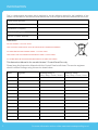
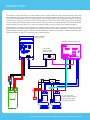
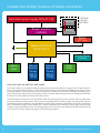
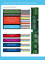
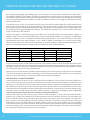
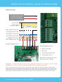
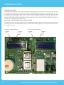
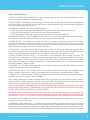
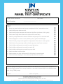
DATA SHEET | INSTALLATION INSTRUCTIONS
INSTALLATION & USER MANUAL
CONTROL PANEL-PRO
SOPHISTICATED TWIN PUMP CONTROL
PRODUCT CODE - CP2 & CP7
Rev 2.4 - 19 May 2015
NEWTON
SYSTEM 500
Newton Waterproofing Systems
Newton House
17-19 Sovereign Way
Tonbridge, Kent TN9 1RH
Tel 01732 360 095 Fax 01732 359 033
E: [email protected]
W: www.newtonwaterproofing.co.uk
© Newton Waterproofing Systems
(a trading name of John Newton & Co. Ltd.)
Newton House, 17-19 Sovereign Way, Tonbridge, Kent, TN9 1RH
T: +44 (0)1732 360 095 W: www.newtonwaterproofing.co.uk E: [email protected]
INFORMATION
This is a dual-purpose document that is designed to be the reference manual for the installation of the
Newton Control Panel-Pro and then should be handed over to the occupier as the user manual and service record.
Panel Serial Number
Date Installed
Installation Company
Installation Engineer
Service Contact Number
WARNINGS
SHOCK HAZARD – DO NOT OPEN.
THIS CONTROL PANEL MUST ONLY BE INSTALLED BY TRAINED ENGINEERS.
NO USER SERVICE PARTS INSIDE PANEL - DO NOT OPEN.
THIS PANEL HAS TWO MAINS POWER INPUTS AND A 12VDC INPUT.
ALL THREE MUST BE ISOLATED BEFORE SERVICE OF PANEL OR PUMPS.
This Instruction Manual is for use with Version 2 Control Panel-Pro only.
Please keep this Instruction Manual with the Control Panel at all times. The service engineer
should confirm findings using the service sheet below.
Date
2
Engineer
Readings Pump 1
Volts / Amp / Count / Hours
Readings Pump 1
Volts / Amp / Count / Hours
For more information visit us online www.newtonwaterproofing.co.uk
CONTENTS & WARRANTY STATEMENT
PAGE
INFORMATION
SERVICE SHEET INTRODUCTION DESCRIPTION OF FEATURES
SET-UP OPTIONS
CONNECTING POWER, PUMPS & OPTIONAL EQUIPMENT SIZING OF NEWTON VICTRON BATTERY BACK-UP SYSTEMS
CONNECTION OF NEWTON DIALER
ENGINEER OPTIONS
USER INSTRUCTIONS SYSTEM AND PANEL MAINTENANCE PANEL TEST CERTIFICATE PANEL INTERNAL WIRING DIAGRAM 2
2
4
5
7
8
12
13
14
15
16
17
18
WARRANTY STATEMENT
Limited Product Warranties
One year limited product warranty from date on delivery note or invoice to the customer. Delivery note must
include the product code number and serial number of the product.
What is covered by this limited hardware warranty?
This limited product warranty covers defects in materials and workmanship.
This limited warranty covers warranty back-to-base (Newton Waterproofing Systems) only for defects in materials
and workmanship. The manufacturer will exchange the product with a product that is new or which has been
manufactured from new or serviceable used parts and is at least functionally equivalent to the original product.
What is not covered by this limited hardware warranty?
This limited product warranty does not cover:
• Products the supplier has not received payment for
• Normal wear and tear
• Problems with electrical power supply
• Failure to follow product installation instructions and user instructions
• Failure to perform preventive maintenance on the supplied product or the system the product is used within
• Usage that is not in accordance with the product instructions
• Servicing not authorised by the manufacturer
• Problems caused by connecting devices not supplied or authorised by the manufacturer
Warranty Information
This warranty gives you specific legal rights, and you may also have other rights which may vary from area to area
(or jurisdiction to jurisdiction). The manufacturer’s responsibility for malfunctions and defects in the product is
limited to repair and replacement as set forth in this warranty statement. All expressed and implied warranties for
the product, including but not limited to any implied warranties and conditions of merchantability and fitness for
a particular purpose, are limited in time to the term of the limited warranty which is the one-year period reflected
on your delivery note or invoice. No warranties, whether expressed or implied, will apply after the limited warranty
period has expired.
We do not accept liability beyond the remedies provided for in this limited product warranty or for consequential
or incidental damages, including without limitation, any liability for third-party claims against you, for damages for
products not being available for use. Our liability will be no more than the amount you paid for the product that is
the subject of a claim. This is the maximum amount for which we are responsible. Newton Waterproofing Systems
reserve the right to change the product specification at any time.
Call us for more information on +44 (0)1732 360095
3
INTRODUCTION
The Newton Control Panel-Pro is a class-leading pump control panel with many unique features which has
been designed by Newton Waterproofing Systems to provide the ultimate in pump operation and diagnosis.
The panel includes interfaces for use with Newton Victron Battery Back-Up and Telemetry Systems as well as
connections to whole house alarm and monitoring systems. The Control Panel PCB is split into two separate
circuits, ensuring that pumping will continue even if one of the control circuits should fail. This effectively means
that the Newton Control Panel-Pro is two control panels within one case, offering unrivalled redundancy.
Self-diagnostic programs test the pumps on a weekly basis to ensure correct pump performance, with the
appointed service engineer automatically informed of any detected problem with either of the pumps if the
Newton Dialer telemetry system is either connected (Newton Purchase Code PA5) or installed within the panel
(Newton Purchase Code CP7). A typical system is shown below:
Victron Battery
Back-Up unit
Newton Control Panel-Pro
Grid mains
power supply
230V AC 13A
2 x Pumps with
sequential pumping,
duty assist & duty
standby operation
Battery
4
For more information visit us online www.newtonwaterproofing.co.uk
DESCRIPTION OF FEATURES
The Newton Control Panel-Pro will operate a maximum of two 750W 230V AC pumps. The panel is supplied
with a vertical water level float switch and high water level alarm float switch. The panel is designed to be
used with optional Newton Victron Battery Back-Up Systems, sized to suit the pumps and installed with
sufficient battery power to ensure continued pumping during power outages.
PANEL HIGHLIGHTS
1. Automatic alternate duty cycle - Each time the main float switch calls for a pump to start, the panel will
alternate the command to each pump to share the pump wear.
2. Two independent power supply inputs - One for grid mains and the other for a battery-backed power
supply via an approved Newton Victron Battery Back-Up System. In the event of a grid mains failure, the
panel automatically switches to battery power. On power restoration, the panel will automatically switch
back to normal grid power mode and recharge the battery or batteries.
3. Alarm on power failure - Panel will alarm on mains failure. The mains fail beep will not sound in mains fail
until a pump operation has occurred, or, if the pumps are not used, the sounder will beep after 12 hours.
This is to prevent unnecessary alarms, mainly at night. An alarm output is sent to trigger the Newton voice
and text Dialer (included with purchase code CP7) or home alarm at the time of the mains power failure.
4. Automatic pump duty assist - If one pump cannot cope with the volume of water entering the sump, the
second pump will automatically start in order to increase the pumping capability. The time period before
the second pump starts is adjustable (master timer setting) to accommodate different sized sumps. There
is also the option to prevent both pumps running at the same time if the system is running from back-up
battery.
5. Automatic current monitoring for each pump - The panel checks that the pump is using the correct current
when the pump has been switched on. If the current is too low or a pump cable has been disconnected the
panel will automatically switch to the second pump. The current in Amps is displayed for running pumps.
As well as the panel audible alarm, an alarm output is sent to trigger the voice or text Dialer (where fitted
or included) or home alarm/monitoring system at the time of a pump failure. There is approximately a 30
second delay before the sounder operates after a pump fault is detected. This is to allow the panel to check
there is indeed a pump fault and to not beep the sounder unless the fault is confirmed.
6. Automatic main float checking - If the main float fails or becomes disconnected, the alarm float
automatically takes over as the main level control float (preset to 10 seconds). If in main float fail mode, the
panel will still alternate both pumps via the alarm float. An alarm output is sent to trigger the voice or text
Dialer in the event of main float failure.
7. Automatic alarm float checking - An alarm checking signal is continually monitored to confirm that the
alarm float cables have been fitted correctly, not been tampered with, or have been disconnected.
8. Each pump has its own, totally separate electronic circuit - This allows for one pump to still operate if a
fault develops in the pump that could damage the panel electronics. An alarm output is sent to trigger the
voice or text Dialer in the event of a controller failure.
9. Automatic testing of each pump every 7 days - Testing ensures the pumps are used each week and
will report any problems detected during the 3 second test with an alarm. Each control circuit has its own
independent timer to ensure that each pump is tested at different times.
10. Each pump is controlled by a zero voltage solid state triac - The triac device is controlled by very fast
switching electronics that can detect the change to the 50Hz cycle to initiate switching at zero voltage.
Unlike mechanical relays or contactors, there are no moving parts to wear out or generate arcing dust or
welding of contacts. This gives the control panel a life duty in the millions of pumping operations unlike a
mechanical relay that can be as low as 100,000 cycles.
11. The panel monitors the power supply and will alarm if the incoming grid mains voltage fails - The panel
will give a loud beep once per minute in grid mains fail mode. The panel will also auto reset on power
return.
Call us for more information on +44 (0)1732 360095
5
DESCRIPTION OF FEATURES
12. The panel monitors the power supply and will alarm if the current to each pump is too high or too
low - The panel automatically checks that the correct power is being used by each pump. If the pump is
disconnected or a pump fuse has blown the panel will give a loud two beeps per minute. The alarm will also
sound if the pump is using too much power. Must be reset by pressing the reset buttons or performing a
full reset of the panel.
13. Alarm sounder options - Dip-switches on the sounder allow for programming of up to 32 different alarm
sounds with a fully adjustable volume control also included.
14. Engineer option to mute all sounds other than high water alarm - This can be set by the engineer after a
full panel reset. Hold down the pump 1 mute / reset button and then press the pump 1 button, then repeat
this twice for each pump. The display will flash up AUX SOUNDER OFF. This will stop any beeping other than
for a high water level if the customer requires it.
15. Each pump circuit has it’s own LCD display with a built in flash memory - This display will:
A) Display and store the pump cycles and hours run in an independent flash memory chip for each pump
B) Display any alarms with the description of the alarm, water level high, pump fault, high current, mains
failure and sounder off
C) Display the pump that is running, the current of the pump and the back-up battery voltage, allowing the
engineer to monitor pump efficiency and battery condition
D) Display the voltage of the converter battery in both grid mains and converter in use modes
E) Display if the panel has had the alarm sounder muted by user
F) Possess an engineer memory reset for resetting all timers and counters
G) Possess a ‘service due’ setting to inform the user that a service is due on the system (this function can be
selected by the engineer)
16. All float switches are 12VDC (low voltage) - Via two separate isolation transformers.
17. Each pump has a manual override button and a reset button - The pump button can be pressed at any
time to operate the pump and the reset button to reset the display after an alarm (will not reset if pumping).
18. Display memory resetting
19. Sounder mute - If the sounder is beeping to warn of mains fail or pump fault you can mute the sounder by
pressing each mute / reset button twice. To remind the user of a muted fault the mute function will cancel
after 12 hours.
20. Engineer reset of counters and timers (engineer only see page 15).
The Newton Control Panel - Pro is designed to be used with all or a selection of the following Newton pumping
options:
• A choice of Newton manual pumps of 400W and 750W
• A range of Newton Victron Battery Back-Up Power Inverters to give continuation of pumping via the panel
during power outage
• Newton Dialer, pre-fitted to code CP7, that will alert up to 8 different land or mobile phones with either text
or voice confirmation of the sounding of the alarm
• Newton PA50 High Water Level Alarm as a remote alarm in another location (requires twin core cable
connection)
• Whole house management system (supplied by others). Home automation relays are mounted on the PCB
to allow panel warnings to operate other systems. The relays are contacts volt free. The relays operate for 5
seconds on pump fault, water high or mains fail. Note that a mains fail is NC whilst the others are NO
6
For more information visit us online www.newtonwaterproofing.co.uk
SET-UP OPTIONS
As mentioned earlier, the panel has two control circuits; Pump 1 and Pump 2. Each circuit has a set of control
dip switches and a timer. The position of these is shown in the diagram below.
Duty Assist Timer
Duration of first pump operation
before second pump starts to
assist
Sounder volume &
tone settings
DIP Switch 1
Call us for more information on +44 (0)1732 360095
High Water Level Alarm Timer
Set at 10 seconds longer than Duty
Assist Timer
DIP Switch 2
Pump 1
10A fuse
Pump 2
10A fuse
7
CONNECTING POWER, PUMPS & OPTIONAL EQUIPMENT
Grid mains power supply 230V AC 13A
Power Inverter
(option)
Battery
OPTIONAL
FURTHER
BATTERIES
Battery
Dialer
CP7 Only
Newton Control
Panel-Pro 2
House Alarm
(option)
Alarm
Float
Manual
Newton
Pump
400 to
750W
Manual
Newton
Pump
400 to
750W
Main
Float
USER SELECTABLE DIP SWITCHES AND TIMERS
The Control Panel-Pro is supplied with the pump duty assist timers (shown on page 7) set to 30 seconds for
Pump 1 and 40 seconds for Pump 2. This is the optimum setting for the Newton NP400 pump within a TitanPro sump chamber. The installer should test the system to ensure that one pump completes a pumping cycle
within this set time, before the second pump turns on to assist. Adjust the timers to suit. Always set the Pump
2 timer to be 10 seconds more than the Pump 1 timer.
The DIP switches are all set to OFF by default. With this setting the Duty assist function will only take place
when the system has mains power. If the system is operating off 12V battery power, the duty assist function
is disabled so that the battery is not drained too quickly. If the system is powered by more than one battery
with a combined storage of over 400Ah, DIP 2 can be changed to ON, allowing for duty assist during power
outages. If a single battery is used, we strongly advise not to use duty assist and that the DIP switches are all
set to the OFF position. Please see page 12 for further information.
8
For more information visit us online www.newtonwaterproofing.co.uk
CONNECTING POWER, PUMPS & OPTIONAL EQUIPMENT
ELECTRICAL CONNECTION
INSTALLATION WARNINGS:
THIS CONTROL PANEL MUST ONLY BE INSTALLED BY TRAINED ENGINEERS.
BEFORE COMMENCING INSTALLATION, ISOLATE YOUR MAINS ELECTRIC SUPPLY.
This product should be installed in accordance with the relevant sections of the building regulations code
and the current edition of the IEE Wiring Regulations (BS 7671: Requirements for electrical installations)
and appropriate statutory regulations.
As of April 2004, new installations in the UK should be wired using the EU harmonised colours for the
supply conductors. NEW COLOURS: BROWN = Live, BLUE = Neutral, YELLOW / GREEN = Earth
This installation MUST be earthed.
This control panel is not waterproof, is of a metal construction, and must be installed in a dry, well
-ventilated area.
Warning: It is important to read and understand the control panel instructions
This Newton twin pump control panel has been designed to be wall-mounted or recessed within the wall.
When the unit is recessed into the wall the routing of all cables is also within the wall making a neater
installation than if the unit is wall-mounted. Cable entry is via the 7 cable glands on the bottom of the panel.
An extension wiring kit for extending the distance from the panel to the pumps up to 50M is available. The
purchase code is PA-31 and is a special order with a two week delivery from order.
For ease of maintenance in changing pumps, it is recommended to only have one mains cable per 20mm
gland. Use the glands as indicated below (numbered from left to right):
1. Mains input cable
2. Power converter input cable
3. Pump one cable
4. Pump two cable
5. Main float cable
6. Alarm float cable.
Notes:
Low-voltage rated cables should not be run in the same conduit as mains (230V AC) cables. The panel must
be earthed, not just earthed via a mains cable with a plug fitted! Use the earthing point mounted inside on
the bottom of the housing by the gland entry points.
If the sump chamber is full of water on first powering up the panel, the alarm may sound and both pumps
may start in sequence in pump duty assist mode. When the water level is below the main float top position,
reset the panel by turning off the power supply for 5 seconds. On power up the system will operate normally.
The display units can be reset after installation. Please see the instructions on page 15.
Call us for more information on +44 (0)1732 360095
9
CONNECTING POWER, PUMPS & OPTIONAL EQUIPMENT
CONNECTION WIRING DIAGRAM
ALARM FLOAT (Low-voltage)
WATER LEVEL FLOAT (Low-voltage)
12V DC FROM BATTERY (Option)
DIALER (CP7 only)
See page 14 for terminal
connects for Dialer and
phone line
HOUSE ALARM SYSTEM
(Option)
GRID MAINS INPUT
230V AC
POWER CONVERTER INPUT
230V AC (option)
PUMP ONE MAINS
OUTPUT 230V AC
PUMP TWO MAINS
OUTPUT 230V AC
10
For more information visit us online www.newtonwaterproofing.co.uk
CONNECTING POWER, PUMPS & OPTIONAL EQUIPMENT
CONNECTION NOTES
• Connection of the grid mains electric supply should be carried out by a competent person
• Ensure that the grid mains connection is not connected until all connections are complete and the Control
Panel casing is fitted and locked closed
• The Control Panel is supplied with terminal connectors. These are fitted into the motherboard terminals
as shown on page 10. The terminal connectors allow for quick connection and disconnection to the
board. Wiring can be connected to the terminal connectors whilst they are fitted to the board or away
from the motherboard
• The Alarm Float is the smaller Reed Pivot Switch and the Level Switch is the larger Vertical Action Float
Switch. The Alarm Float should be installed so that the switch is always closed and only opens when lifted
upwards by rising water
• Both the Level and Alarm floats have two wires. The connection of these wires is not dependent on
polarity and can be fitted to either of the terminals for each connection
• The Level Switch should be connected to the vertical discharge pipe of one of the pumps at a height that
allows for the pumps to operate correctly. If the switch is too high, the switch may not operate until the
water level in the sump is too high. If the switch is too low, it is possible that the pump removes all the
water before the switch has turned off. It is vitally important to test the pump switching to ensure the
pumps operate correctly
• The Alarm Float should be fitted to the vertical discharge pipe of one of the pumps at a height that is
above the Level Switch
Call us for more information on +44 (0)1732 360095
11
SIZING OF NEWTON VICTRON BATTERY BACK-UP SYSTEMS
As an approximate guide, with 400W pumps, one can expect to pump about 10,000 litres of water with a
full Odyssey 100Ah PC2150 battery. This figure is based upon a system with a new battery and the pumps
operating to approximately a 4M head with approximately 15 minutes between cycles, allowing for battery
recovery time in between each operation. Further information can be found on page 3 of the Newton Victron
Inverters Data Sheet.
The default set-up of this Control Panel has the ‘pump duty assist’ disabled when the mains power fails to
prevent very high current draw from the battery if running two pumps together. This setting protects the
back-up battery from sudden discharge and will allow the system to pump more water for much longer with
the limited power supply available in the battery. The default DIP setting is OFF on all four DIPs on both the
Pump 1 and Pump 2 DIP switches.
If pump duty assist is required during a power failure we recommend that a minimum battery capacity of
400Ah is used. This can be multiple batteries connected in parallel (4x 100Ah or 2 x 214Ah) or a single large
battery of 400Ah or over. To change the default setting, change DIP 2 on both DIP Switches to ON. Note:
Approximately 100 Litres water pumped = per 1 Amp of power in the battery in a mains power failure,
although other factors can further reduce this figure, such as the quality, storage temperature and age of the
battery, the discharge pipe bore length, and the number of bends, tees and elbows.
POWER CONVERTER SIZING
PUMP SIZE
DUTY ASSIST
DIP 2 SETTING
CONVERTER
SIZE OF BATTERIES
400W
NO
OFF
1200W
100Ah or more
400W
YES
ON
3000W
400Ah or more
750W
NO
OFF
3000W
100Ah or more
750W
YES
ON
3000W
400Ah or more
Only use Newton Victron Power Inverters with this Control Panel. Newton Victron Power Inverters have been
designed to work with Newton Pumps and have special software for battery charging and converter cooling.
All Newton Power Converters are tested and calibrated to very high standards before being dispatched from
the factory and meet all UK safety requirements.
Newton Victron Power Inverters include powerful charging circuits and special cooling fan control software.
The Power Inverters are silent when in standby mode, the only time the fan will switch on is to re-charge the
battery or when the Inverter is under heavy load and powered via the battery.
INSTALLATION OF POWER INVERTERS
Power Inverters must be stored in dry conditions before installation. Power Inverters must be installed in a
dry cool area, with good air circulation and NOT above an open-vented lead acid battery or sealed in an air
tight box. Do not install the Power Inverter near the head of a bed or opposite a wall where someone sleeps.
All installations that have grid mains and generated mains power must be correctly labelled, to inform the
user that both power supplies must be isolated before maintenance. Power Inverters can cause electrocution;
take great care to isolate mains and battery before working on systems by unplugging them. Follow the
instructions included with the Inverter for battery sizing and installation.
Batteries, although only 12V, have very high currents of 300 Amps plus, so if you short the terminals with a
spanner, ring or watch for example, they would become white hot in less than 1 second. For this reason you
must remove all metallic rings, watches or any object that may cause a short. If the battery is an open vent
type, you must wear safety glasses and PPE to prevent acid burns. The Power Converter must not have the
mains power connected when fitting the battery cables. Joints must be dry and clean. It is very important
that the connection is good and secure as a bad joint will heat-up and cause the cable insulation to melt (fire
risk), the voltage to vary, and the Power Converter electronics will be damaged. The battery terminals MUST
be covered by a tamper-proof method and not exposed.
12
For more information visit us online www.newtonwaterproofing.co.uk
CONNECTION OF NEWTON DIALER TO CONTROL PANEL
WIRING DIAGRAM
12V FROM BATTERY
OR 12V POWER
SUPPLY (1A FUSED)
Phone Line R
Phone Line T
See note 1 below
Earth to
Dialer Earth
Dialer Trigger input GND
BF Trigger to Terminal 2 - Not used
MF Trigger to Terminal 4
HA Trigger to Terminal 1
F Trigger to Terminal 3
Dialer Trigger input +12V
DIALER TRIGGER INPUTS
PROGRAMMED INPUTS
1. Water Level High
2. Not used
3. Pump Requires Attention
4. Pump Mains Failure
All warnings followed by “press
button 8 to acknowledge”
WARNING - Outputs from the Control Panel to the Newton Dialer are +5V triggers. DO NOT SHORT
TERMINALS TO +12V TO TEST AS THIS WILL DAMAGE THE CONTROL PANEL PCB.
Note 1: Connection of the phone line to the panel is only required when the Dialer is fitted within
the panel housing. The panel terminals receive the T & R wires from the phone line and further T & R
wires connect from the terminals to the Dialer, effectively using the panel terminals as a junction box.
If the Dialer is fitted externally to the panel, only the Earth is required from the Dialer to the panel.
Call us for more information on +44 (0)1732 360095
13
ENGINEER OPTIONS
SERVICE DUE SETTING
The engineer can select the service due function by adding a jumper to both service timer contacts. This will
time down from 365 days to “service due” (will not time days when the panel is not powered up). To reset
the service timer, add jumper links to both service timer and display reset links. Press and hold down the
reset buttons until the display reads memory reset. You have to do this for each pump display. If service due
setting is NOT required do not place the jumpers on the two “service timer” links. See below for position of
service timer & display reset jumper links.
RESETTING COUNTER MEMORY AND SERVICE TIMES
To reset the counter and hour meters link the display reset jumper and remove the service timer link. Press
the rest button until the display reads memory reset. After resetting replace the service timer link & remove
the display reset link.
Pump 1 Jumper Settings
Display
Link
14
Pump 2 Jumper Settings
Service
Timer
Link
Display
Link
Service
Timer
Link
For more information visit us online www.newtonwaterproofing.co.uk
USER INSTRUCTIONS
DISPLAY INFORMATION
1. PUMP CYCLES & PUMP HOURS RUN - (Default display) Displays the cycles and running hours for each
pump from date of installation or engineer reset
2. HIGH CURRENT - Warning of a pump pulling more current than normal. This information may be displayed
when both pumps are running or in mains failure mode. CALL ENGINEER only if this information is displayed
in normal use for longer than 24 hours
3. WATER HIGH ALARM - This warning happens when:
A. The water level reaches the small alarm float or the wires to the alarm float have been cut
B. The main float has failed or the wires to the main float have been cut
C. Both pumps have failed and no water is being pumped from the sump chamber
DANGER OF FLOODING - CALL ENGINEER. Check power is on to the Panel, check cables and float switches,
check any fuses. Requires both reset buttons to be pressed to reset the warning
4. MAINS FAILURE - Grid mains to the Panel is off and it is running on emergency power from the Power
Converter and battery. The alarm will beep once per minute after a pump cycle during mains failure.
Depending on the amount of water flow, battery age and condition, the running time from one battery can
vary from minutes to days. Auto-reset on power restoration
5. PUMP FAULT - This indicates that one of the pumps is either not connected, damaged, pumping air or
an internal pump protection fuse has blown (10A) due to a major pump fail. The alarm will BEEP twice per
minute 30 seconds after the pump failure. CALL ENGINEER . Press both reset buttons to reset
6. PUMP CURRENT, BATTERY VOLTS - This information is only displayed when a pump is running. The
information is for the engineer to monitor the current that each pump is using and the condition of the backup battery voltage. This information is also useful in mains fail mode to check the back up battery voltage
when a pump is running. The voltage in normal use on grid mains should be 13.5 -14.8 Volts, this indicates
the back up battery is being charged
7. SOUNDER OFF - This information warns the user the alarm sounder has been MUTED. If the alarm sounder
is active and cannot be reset, CALL ENGINEER
8. DISPLAY BACK-LIGHT - The backlight will be on low when the panel is powered up. The backlight will go
bright to indicate which pump is running, the display will show the pump current and battery voltage
9. SERVICE DUE - This information indicates the service option has been activated by the engineer and the
annual pump service is now due. CALL ENGINEER
Note, warning information or alarm sounders can be reset by pressing the reset buttons (it will not reset if
pressed while the display back-light is bright or the pumps are running). The reset will only happen if the
reason of the warning has been corrected. If it cannot be reset, CALL ENGINEER.
To MUTE the sounders. Each display has its own internal warning sounder and the panel has one main
alarm sounder. ONLY MUTE THE SOUNDERS IF YOU ARE SURE. CALL ENGINEER IF THE PANEL INDICATES
A FAULT OR SOUNDS AN ALARM YOU CANNOT RESET.
To mute an alarm. Press the mute buttons twice on each pump when the pumps are not running. This
will mute the sounder for 12 hours only. To remind the user of a muted fault the mute function will
cancel after 12 hours. YOU CAN ONLY MUTE THE SOUNDER WHEN THE PUMP(S) ARE NOT RUNNING.
TO CANCEL MUTE (sounder off), turn both grid mains and inverter mains off for approximately 5 seconds.
This will reset the mute function.
OPERATING A PUMP MANUALLY . To operate each pump manually, press the pump button. The display
back-light will brighten and the display will show pump current in amps and the back-up battery voltage.
Both pumps can be operated if the panel is operating on mains power. If the panel is powered via the
Power Converter and battery, the panel (with default settings) will allow one pump to operate at a time.
Call us for more information on +44 (0)1732 360095
15
SYSTEM & PANEL MAINTENANCE
EVERY MONTH
1. Test the water high float each month by lifting the float switch in the sump chamber. The sounder will
sound and one of the pumps will start for 10 seconds. When the pump has stopped press both reset buttons
for approximately 5 seconds each (if a Dialer is connected answer the call and press button 8 on the phone
to acknowledge alarm)
2. Press each pump button for approximately 5 seconds in turn to check each pump is working (the panel
does an automatic check each week for a 3 second test on each pump)
3. Check the panel displays for any warnings, if any, note and press both of the reset buttons for approximately
5 seconds and check display again after the next pumping cycle. If the warning has not cleared contact your
service company
EVERY 6 MONTHS
1. The panel does not contain any serviceable items. Wipe the outside of the panel case with a dry clean
cloth
EVERY 12 MONTHS
1. The system will require servicing by a qualified service engineer to check:
A. The condition of the pumps for wear or loss of efficiency
B. The service / pump timers
C. The amount of water pumped by the system since the last service
D. The condition of the sump and any deposits in the bottom of the chamber
E. The condition of the Basedrain, pipe work and water outlet pipes
F. The back-up battery condition (voltage and capacity under load)
G. The condition of the large cables from the battery to the converter and the battery connections
H. The condition of the Power Inverter, if fitted (test back-up system by turning off the mains to both the
Panel and Power Converter)
I. Test the Dialer if installed
J. Reset service timers and counters if required
RECORD THE SERVICE USING THE SHEET ON PAGE 2.
16
For more information visit us online www.newtonwaterproofing.co.uk
SYSTEM & PANEL MAINTENANCE
PANEL TEST CERTIFICATE
Panel Serial Number
........................................ Test Date ......................
Part Number
........................................
TEST
1.
Power up panel and test each pump completes its first 3 second burst test
2.
Check both pump buttons work
3.
Check both pumps alternate with water at high flow (minimum of 10 cycles)
4.
Check water high alarm float works (disconnect main float)
5.
Check if pumps alternate in alarm condition and pump for 10 seconds each
6.
Check displays for correct current, battery volts, cycles and back light
7.
Check if both pumps work together in high water flow rates on mains power
8.
Check that only one pump works on back-up power only from converter
9.
Check dialler, display and sounder for water high alarm
10. Check dialler, display and sounder for mains fail
11. Check dialler, display and sounder for pump fault
12. Check sounder mute functions
13. Check pumps run for a minimum of 20 full cycles in normal mode
14. Check and reset displays to zero (check jumper links are in place)
o
o
o
o
o
o
o
o
o
o
o
o
o
o
Notes:
This twin pump control panel has been tested to the above tests. All tests are completed on a
test rig pumping water from a sump chamber to an outlet 4 metres high from chamber water
level, using 750W pumps.
Signed .................................................................. Name In Capitals .......................................................
© Newton Waterproofing Systems
(a trading name of John Newton & Co. Ltd.)
Newton House, 17-19 Sovereign Way, Tonbridge, Kent, TN9 1RH
T: +44 (0)1732 360 095 W: www.newtonwaterproofing.co.uk E: [email protected]
Call us for more information on +44 (0)1732 360095
17
PANEL INTERNAL WIRING DIAGRAM
18
For more information visit us online www.newtonwaterproofing.co.uk
Call us for more information on +44 (0)1732 360095
19
Newton Waterproofing Systems
(A Trading Name Of John Newton & Co Ltd)
Newton House
17-19 Sovereign Way
Tonbridge, Kent TN9 1RH
T: 01732 360 095 F: 01732 359 033
E: [email protected] W: www.newtonwaterproofing.co.uk
20
For more information visit us online www.newtonwaterproofing.co.uk