1
Addendum to
Users Manual
Ranger
Wedge Interface
Part No. 25-WEDGE-06A
Ver. April 1999
8 Olympic Drive
Orangeburg, NY 10962
Tel 845.365.0090
Fax 845.365.1251
www.opticonUSA.com
Table of Contents
Read Me First ................................................... 1
General Information .......................................... 1
Laptop Operation .............................................. 3
SureOne Operation ............................................ 4
Understanding Data Transmission ...................... 5
AIM Code ID ..................................................... 6
Programming a Prefix or Suffix Option ................ 7
Laptop & SureOne Models ................................. 8
Default & Caps Lock Selection ............................ 9
Symbologies Prefix Selection ............................ 10
Symbologies Suffix Selection ............................ 11
UCC-128 & AIM Code ID Options ...................... 12
Suffix-1 Options .............................................. 13
AIM Code ID Interpretation .............................. 14
Alpha-Numeric Characters Table ....................... 15
ASCII-HEX Character Chart .............................. 17
Linker (Wand) Output Functions ....................... 20
Read Me First
This scanner provides additional functionality
beyond those available in a standard wedge-only
scanner. Prior to performing any programming to
address these features, it is important to
understand what these functions are and how to
use them. The following will explain the operation
and programming of the additional functions.
General Information
The RANGER scanner can operate in either a
wedge, wand emulation or SureOne mode using
the appropriate cable adapters. It can also be
used to operate with a laptop computer with the
appropriate adapter cable. A SureOne Kit scanner,
although capable of operating in other modes, is
terminated in a connector specific to the SureOne
terminal and should not be programmed to
operate in other than the SureOne or Laptop
mode.
In the wedge mode, a RANGER operates like any
wedge scanner, namely, it emulates a keyboard
input to the device to which it is connected. Some
devices, primarily decoder boxes and data
collection terminals, are designed to operate with a
pen-style (or wand) scanner. A RANGER scanner
can be programmed to operate as a wand
scanner simply by attaching the wand emulation
adapter cable. Once in wand emulation mode,
the scanner can be programmed for the wand
options using the menu on page 20.
Page 1
The programming menu on page 9 allows
programming of the scanner to the default settings
for either the wedge or wand emulation mode.
NOTE: Do not set Wedge defaults while in the
wand emulation mode or set wand emulation
defaults when in the Wedge mode.
Default settings for any option (if applicable) are
).
indicated bya pointing finger (
B
Additionally, the RANGER scanner (in the wedge
mode) can be commanded to ignore the state of
the Caps Lock key. Normally (default mode), a
scanned character will be transmitted to the
computer in agreement with the state of the Caps
Lock key, e.g., a lower case character will be sent
as an uppercase character (and vice versa) if Caps
Lock key is ON. However, if the Caps Lock function
is enabled, the scanner will ignore the state of the
Caps Lock key and send the character as scanned,
e.g., a lowercase character will be sent in
lowercase, even if Caps Lock is ON. The
programming codes for enabling/disabling this
feature can also be found on page 9.
Page 2
Laptop Operation
A laptop computer contains an integrated keyboard
whereas a desktop computer uses an external
keyboard. When using a desktop computer with a
scanner that is designed to emulate keyboard
input, the scanner is wedged into the cable that
connects the external keyboard to the computer
(hence, the term wedge scanner). Since a
laptop keyboard is internal, there is no cable
accessible to use a standard wedge connection for
a scanner. However, most laptops make provision
for an external keyboard via a separate keyboard
connector (or port). Since the scanner
connections to the laptop are different from the
connections to a desktop computer, the scanner
must be programmed specifically to operate as an
external keyboard device. This is accomplished by
using the programming codes on page 9.
IMPORTANT NOTE: Upon power-up, the laptop
checks to see what is connected to its external
ports and sets its internal operation accordingly. If
the scanner is not connected to the laptop prior to
turning on the power, the laptop will not see the
scanner, even when you subsequently plug it in
and program the scanner for laptop operation.
The scanner must be plugged into the laptop prior
to turning on the power on or the laptop must be
rebooted once the scanner has been connected in
order for the laptop to recognize presence of the
scanner. This can be done before or after the
scanner has been programmed for laptop
operation.
Page 3
SureOne Operation
A SureOne Kit scanner is designed to operate with
the IBM SureOne POS terminal and operates
similar to the laptop mode of operation. Use the
codes on page 9 to set the scanner to the SureOne
operation mode.
Page 4
Understanding
Data Transmission
When a decoded bar code scanner reads a bar
code, it interprets the bar code symbol and sends
it in digital form to the receiving device in the form
of an ASCII character that the symbol represents.
With a wedge scanner, the code is received as if it
were typed on a keyboard.
Many applications require or can be simplified by
transmitting other characters with the decoded
bar code data. These additional character
command the computer to take some action.
Skipping a line (line feed command), adding text
to the transmitted data, or taking another brand in
its programming sequence are some example of
what could be one by adding characters before
(prefixes) or after (suffixes) the decoded data.
This scanner allows these additions in the wedge
mode only. The generalized data transmit format
is:
time - - >
PREFIX
CODE
ID
DATA
SUFFIX
-1
SUFFIX
-2
SUFFIX-1 is used for cursor control and can be
added independently of the symbology in use
whereas the PREFIX and SUFFIX-2 options are
programmed per symbology and will only have an
effect on the symbology they are programmed for.
Therefore, a symbology identifier must be
programmed prior to their addition.
Page 5
For example, if the letter A is to be added as a
suffix to every transmission of a decoded CODE-39
bar code, the code R1 located in the
Symbologies Suffix Selection table must be
scanned prior to scanning the ASCII code for the
letter A suffix. This procedure is more fully
described on page 7.
AIM Code ID
In addition to adding prefixes and suffixes, AIM
Code ID may also be added to the transmitted
data in the format above (AIM is an acronym for
Automatic Identification Manufacturers Association). It is an optional industry standard code
that, when transmitted, may be used by the
application software as a shortcut method of
describing some facets of a scanners operating
mode.
All symbologies will transmit an AIM Code ID
simply by enabling the AIM Code ID function with
the exception of UCC/EAN-128, which requires a
separate symbology enabling/disabling programming code in addition to the AIM Code ID.
The table on page 12 show the various output
combinations possible for the UCC/EAN-128
symbology.
Page 6
Programming
a Prefix or Suffix Option
After scanning the START/END code on page 10
or 11, select the desired symbology to add a prefix
or suffix by scanning the appropriate code under
the Symbologies Suffix Selection table (Note: All
prefixes or suffixes previously assigned to this
symbology will be erased).
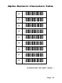
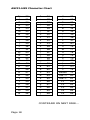
Each prefix or suffix character is assigned a two
digit (ASCII) code identifier. Look up the code for
the character(s) desired as either a prefix or suffix
in the ASCII-HEX Character Chart located on pages
17-19. Using the alphanumeric bar codes on
pages 15 and 16, scan the two digit identifier for
the first character of the prefix/suffix. Repeat
scanning additional two digit identifiers for up to 4
characters maximum. The Back Space and Clear
All bar codes can used to correct any errors in
scanning. Back Space clears the previous alphanumeric code or the previous character. Clear All
erases all previously scanned characters.
Repeat the above (starting with selecting a new
symbology) for any other symbologies or end the
procedure by scanning the START/END code.
Page 7
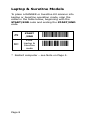
Laptop & SureOne Models
To place a RANGER or SureOne Kit scanner into
Laptop or SureOne operation mode, scan the
codes in the table below, beginning with the
START/END code and ending the START/END
code.
Z9
START
/END
,Z9,
KC
Enter
Laptop &
SureOne
mode
,KC,
* Restart computer see Note on Page 4.
Page 8
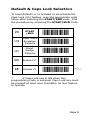
Default & Caps Lock Selection
To reset defaults or to activate or de-activate the
Caps Lock (CL) feature, scan the appropriate code
below after scanning the START/END code. End
the procedure by scanning the START/END Code.
Z9
START
/END
,Z9,
U4
Reset Wand
Emulation
Defaults
,U4,
U1
Reset
Wedge
Defaults
,U1,
KD
Enable CL*
,KD,
KE
Disable CL
,KE, B
*
If Caps Lock key is ON when this
programming code is scanned, Caps Lock key must
be pressed at least once thereafter for this feature
to operate.
Page 9
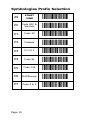
Symbologies Prefix Selection
Z9
START
/END
,Z9,
P0
Code UPC &
Variants
,P0,
P1
Code 39
,P1,
P2
Codabar
,P2,
P3
D 2 of 5
,P3,
P4
Code 93
,P4,
P5
Code 128
,P5,
P6
MSI/Plessey
,P6,
P7
Code 4 & 5
,P7,
Page 10
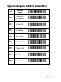
Symbologies Suffix Selection
Z9
START
/END
,Z9,
R0
Code UPC
& variants
,R0,
R1
Code 39
,R1,
R2
Codabar
,R2,
R3
D 2 of 5
,R3,
R4
Code 93
,R4,
R5
Code 128
,R5,
R6
MSI/Plessey
,R6,
R7
Code 4 & 5
,R7,
Page 11
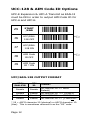
UCC-128 & AIM Code ID Options
UPC-E Expansion & UPC-A Transmit as EAN-13
must be ON in order to output AIM Code ID for
UPC-A and UPC-E.
,Z9,
Z9
START
/END
J6
UCC/EAN128 OFF
,J6, B
J7
UCC/EAN128 ON
,J7,
J8
AIM Code
ID OFF
,J8, B
J9
AIM Code
ID * ON
,J9,
UPC/EAN-128 OUTPUT FORMAT
UCC/
EAN-128
AIM
ID
Disable
Disable
FNC1ABCFNC1D => ABCD
(Default)
Disable
Enable
FNC1ABCFNC1D => ]C1ABCD
Enable
Enable
Disable FNC1ABCFNC1D => ABC29D *
Enable FNC1ABCFNC1D => ]C1ABC29D *
FORMAT
* 29 = ASCII character 29 (decimal) or ASCII character 1D
(Hex). This is sometimes referred to as the GS code.
Page 12
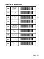
Suffix-1 Options
Z9
START
/END
,Z9,
O0
No suffix
,O0,
O1
Carriage
return
,O1, B
O2
Line feed
,O2,
O3
Carriage
return and
line feed
,O3,
O4
Tab
,O4,
O5
Shift tab
,O5,
OA
Arrow down
,OA,
OB
Tab and
Space
,OB,
Page 13
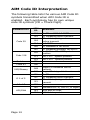
AIM Code ID Interpretation
The following table lists the various AIM Code ID
symbols transmitted when AIM Code ID is
enabled. Each symbology has its own unique
code ID symbols (CD = Check Digit).
SYMBOLOGY
Code 39
Code 128
AIM
ID
MEANING
JA0
JA1
No CD and NO full ASCII
CD validated before transmit
JA3
CD validated/stripped
before transmit
JA4
Full ASCII conversion
JA5
CD validated & full ASCII
JA7
CD validated/stripped, full ASCII
JC0
No FNC1 in 1st or 2nd symbol
position
JC1
JC2
FNC1 in 1st symbol position
FNC1 in 2nd symbol position
Codabar
JF0
Code 93
JG0
MSI/Plessey
JM0
JM1
D 2 of 5
JI0
No CD
JI1
CD validated before transmit
CD validated/stripped before
transmit
JI3
I 2 of 5
UPC/EAN
Page 14
Single CD validated before
transmit
Single CD stripped before transmit
JS0
JE0
Standard UPC-A, UPC-E (13 digits)
JE3
With add-on code
JE4
EAN-8 data packet
Alpha-Numeric Characters Table
0
,00,
1
,01,
2
,02,
3
,03,
4
,04,
5
,05,
6
,06,
7
,07,
8
,08,
CONTINUED ON NEXT PAGE...
Page 15
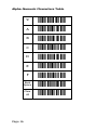
Alpha-Numeric Characters Table
Page 16
9
,09,
A
,0A,
B
,0B,
C
,0C,
D
,0D,
E
,0E,
F
,0F,
Back
Space
,0G,
Clear
All
,0H,
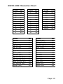
ASCII-HEX Character Chart
Code Char ID
NUL
^@ 00
SOH
^A
01
STX
^B
02
ETX
^C
03
EOT
^D 04
ENQ
^E
05
ACK
^F
06
BEL
^G 07
BS
^H 08
HT
LF
VT
FF
CR
SO
SI
^I
^J
^K
^L
^M
^N
^O
09
0A
0B
0C
0D
0E
0F
Code Char ID
DLE
^P
10
DC1
^Q 11
DC2
^R
12
DC3
^S
13
DC4
^T
14
NAK
^U 15
SYN
^V
16
ETB
^W 17
CAN
^X
18
EM
SUB
ESC
FS
GS
RS
US
^Y
^Z
^[
^\
^]
^^
^_
19
1A
1B
1C
1D
1E
1F
CONTINUED ON NEXT PAGE...
Page 17
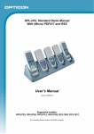
ASCII-HEX Character Chart
Sp
!
#
$
%
&
20
21
22
23
24
25
26
*
+
,
.
/
0
2A
2B
2C
2D
2E
2F
30
4
5
6
7
8
9
:
34
35
36
37
38
39
3A
(
)
>
?
27
28
29
3E
3F
1
2
3
Z
[
31
32
33
5A
5B
;
<
=
v
w
3B
3C
3D
76
77
@
A
B
C
D
E
F
G
H
40
41
42
43
44
45
46
47
48
\
]
^
_
`
a
b
c
d
5C
5D
5E
5F
60
61
62
63
64
x
y
z
{
|
}
~
Delete
Tab ->
78
79
7A
7B
7C
7D
7E
7F
80
I
J
K
L
M
N
49
4A
4B
4C
4D
4E
e
f
g
h
i
j
65
66
67
68
69
6A
TAB <F1
F2
F3
F4
F5
81
82
83
84
85
86
CONTINUED ON NEXT PAGE...
Page 18
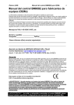
ASCII-HEX Character Chart
Char
O
P
Q
R
S
T
U
V
W
X
Y
ID
4F
50
51
52
53
54
55
56
57
58
59
Char
k
l
m
n
o
p
q
r
s
t
u
ID
6B
6C
6D
6E
6F
70
71
72
73
74
75
Char
F6
F7
F8
F9
F10
F11
F12
PgUp
PgDn
ID
87
88
89
8A
8B
8C
8D
8E
8F
Char
Home
End
Up Arrow
ID
90
91
92
Char
PgDn (KP)
Delete (KP)
Insert (KP)
ID
9D
9E
9F
Dn Arrow
Lft Arrow
Rgt Arrow
Enter/CR
Home (KP)
Up Arrow (KP)
Dn Arrow (KP)
Rgt Arrow (KP)
Lft Arrow (KP)
PgUp (KP)
93
94
95
96
97
98
99
9A
9B
9C
End (KP)
Enter (KP)
Esc
Insert
Alt-ON
Alt-OFF
Ctrl-ON
Ctrl-OFF
Shift-ON
Shift-OFF
A0
A1
A2
A3
A4
A5
A6
A7
A8
A9
Page 19
Linker (Wand) Output Functions
Z9
START
/END
,Z9,
S0
Output
1 to 1
,S0, B
S1
Output in
Code 39
,S1,
S2
Output
speed =
high
,S2, B
S3
Output
speed = low
,S3,
S4
Output bar
= low
,S4,
S5
Output bar
= high
S6
Output with
margin
S7
Output w/o
margin
Page 20
,S5, B
,S6, B
,S7,
This Addendum to the Wedge manual contains
programming codes for operating a handheld CCD
scanner designed with any of the following model
names:
RANGER®
SureOne Kit
Wedge Linker Interface
and offers the following features:
Laptop Operation
Wand Emulation
UCC-128 Symbology
Extended Prefixes & Suffixes
NOTE: All programming codes in the Wedge
Manual (25-WEDGE-06) apply to the Wedge
operating mode ONLY with the exception of the
following, which apply to both Wedge AND Linker
(WAND) operation: Symbology Selection;
Symbology Addition, Code 39 (C0 & C1, D2, D3,
D4, D5); Codabar (E0, E1, E4, E5, F5, F6); 2 of 5
(G0, G1, G6, G7); Code 128 (C6 through J5); Bar
Code Length Options; Trigger Options; Beeper
Settings (except W1 & W5); and Read Mode.
Also, located on page 30 of 25-WEDGE-06, D1 is
Default (Not D0); page 31, E4 is Default (Not E5);
and page 24, A0 reads all codes except MSI/
Plessey, Code 4 or Code 5.
RANGER is a trademark of Opticon, Inc.
SureOne is a registered trademark of IBM Corporation
Page 21